2011 INFINITI QX56 engine oil
[x] Cancel search: engine oilPage 5284 of 5598
![INFINITI QX56 2011 Factory Service Manual
TM-196
< REMOVAL AND INSTALLATION >[7AT: RE7R01B]
OUTPUT SPEED SENSOR
4. Remove clips (1).
5. Remove oil pan (2) and oil pan gasket.
6. Support A/T assembly with a transmission jack.
CAUTION:
When se INFINITI QX56 2011 Factory Service Manual
TM-196
< REMOVAL AND INSTALLATION >[7AT: RE7R01B]
OUTPUT SPEED SENSOR
4. Remove clips (1).
5. Remove oil pan (2) and oil pan gasket.
6. Support A/T assembly with a transmission jack.
CAUTION:
When se](/manual-img/42/57033/w960_57033-5283.png)
TM-196
< REMOVAL AND INSTALLATION >[7AT: RE7R01B]
OUTPUT SPEED SENSOR
4. Remove clips (1).
5. Remove oil pan (2) and oil pan gasket.
6. Support A/T assembly with a transmission jack.
CAUTION:
When setting transmission j ack, place wooden blocks to
prevent from damaging control valve & TCM and transmis-
sion case.
7. Remove rear engine mounting cross member with power tool. Refer to TM-205, "
2WD : Exploded View".
8. Remove engine mounting insulator (rear). Refer to TM-205, "
2WD : Exploded View".
9. Remove tightening bolts for rear extension assembly and trans- mission case.
10. Tap rear extension assembly with a soft hammer (A). CAUTION:
Be careful not to damage rear extension case.
11. Remove rear extension assembly (with needle bearing) from transmission case.
: Vehicle front
: Oil pan mounting bolt
1 : Bracket
A: Bolt
B : Self-sealing bolt
JSDIA1591ZZ
JSDIA1845ZZ
JPDIA0027ZZ
SCIA3431E
Revision: 2010 May2011 QX56
Page 5411 of 5598

WCS
SYSTEMWCS-7
< SYSTEM DESCRIPTION >
C
DE
F
G H
I
J
K L
M B A
O P
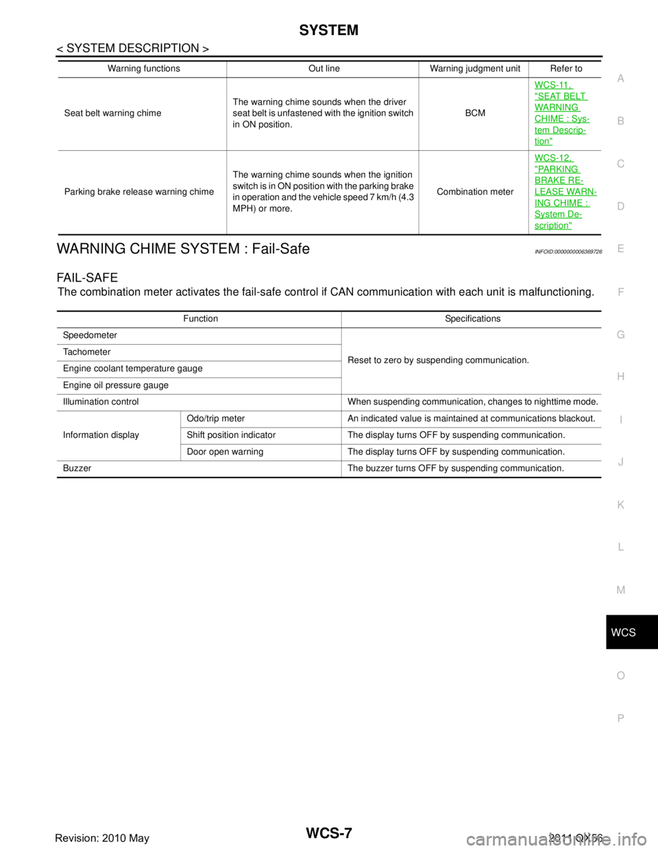
WARNING CHIME SYSTEM : Fail-SafeINFOID:0000000006369726
FA I L - S A F E
The combination meter activates the fail-safe contro l if CAN communication with each unit is malfunctioning.
Seat belt warning chimeThe warning chime sounds when the driver
seat belt is unfastened with the ignition switch
in ON position. BCMWCS-11,
"SEAT BELT
WARNING
CHIME : Sys-
tem Descrip-
tion"
Parking brake release warning chime
The warning chime sounds when the ignition
switch is in ON position with the parking brake
in operation and the vehicle speed 7 km/h (4.3
MPH) or more. Combination meterWCS-12,
"PA R K I N G
BRAKE RE-
LEASE WARN-
ING CHIME :
System De-
scription"
Warning functions Out line Warning judgment unit Refer to
Function Specifications
Speedometer
Reset to zero by suspending communication.
Tachometer
Engine coolant temperature gauge
Engine oil pressure gauge
Illumination control When suspending communication, changes to nighttime mode.
Information display Odo/trip meter An indicated value is maintained at communications blackout.
Shift position indicator The display turns OFF by suspending communication.
Door open warning The display turns OFF by suspending communication.
Buzzer The buzzer turns OFF by suspending communication.
Revision: 2010 May2011 QX56
Page 5421 of 5598

WCS
DIAGNOSIS SYSTEM (COMBINATION METER)
WCS-17
< SYSTEM DESCRIPTION >
C
D E
F
G H
I
J
K L
M B A
O P
*: DDS (hill descent control) NOTE:
Some items are not available according to vehicle specification.
SPECIAL FUNCTION
Special menu
W/L ON HISTORY
Stores histories when warning/indicator lamp is turned on.
“W/L ON HISTORY” indicates the “TIME” when the warning/ indicator lamp is turned on.
The “TIME” above is:
- 0: The condition that the warning/indicator lamp has been turned on 1 or more times after starting the engine and waiting for 30 seconds.
- 1 - 39: The number of times the engine was restarted after the 0 condition.
- NO W/L ON HISTORY: Stores NO (0) turning on history of warning/indicator lamp.
NOTE:
W/L ON HISTORY is not stored for approximately 30 seconds after the engine starts.
Brake warning lamp does not store any history when the parking brake is applied or the brake fluid level gets
low.
Display Item
FUEL LOW SIG
[On/Off] Status of fuel level low warning signal to output to AV control unit via CAN com-
munication.
TOW MODE IND
[On/Off] Status of TOW mode indicator lamp judged from TOW mode indicator lamp signal
received from TCM with CAN communication line.
BUZZER
[On/Off] XBuzzer status (in the combination meter) is detected from the buzzer output signal
received from each unit via CAN communication and the warning output condition
of the combination meter.
Display item [Unit]
MAIN
SIGNALS Description
Display item Description
W/L ON HISTORY Lighting history of warning lamp and indicator lamp can be checked.
Display item Description
ABS W/L Lighting history of ABS warning lamp.
VDC/TCS IND Lighting history of VDC OFF indicator lamp.
SLIP IND Lighting history of VDC warning lamp.
BRAKE W/L Lighting history of brake warning lamp.
DOOR W/L Lighting history of door open warning.
TRUNK/GLAS-H This item is displayed, but cannot be monitored.
OIL W/L Lighting history of oil pressure warning lamp.
C-ENG W/L Lighting history of malfunction indicator lamp.
C-ENG2 W/L This item is displayed, but cannot be monitored.
CRUISE IND Lighting history of CRUISE indicator lamp.
SET IND Lighting history of SET indicator lamp.
CRUISE W/L Lighting histor y of CRUISE warning lamp.
BA W/L Lighting history of IBA OFF indicator lamp.
O/D OFF IND This item is displayed, but cannot be monitored.
ATC/T-AMT W/L Lighting history of A/T CHECK warning lamp.
ATF TEMP W/L This item is displayed, but cannot be monitored.
CVT IND This item is displayed, but cannot be monitored.
SPORT IND This item is displayed, but cannot be monitored.
Revision: 2010 May2011 QX56
Page 5433 of 5598

WCS
COMBINATION METERWCS-29
< ECU DIAGNOSIS INFORMATION >
C
DE
F
G H
I
J
K L
M B A
O P
Fail-SafeINFOID:0000000006222689
FA I L - S A F E
The combination meter activates the fail-safe contro l if CAN communication with each unit is malfunctioning.
37
(R/Y) Ground Non-manual mode signal Input Ignition
switch
ONSelector manual mode po-
sition
12 V
Other than the above 0 V
38
(L/W) Ground Manual mode shift down
signal InputIgnition
switch
ON Selector lever DOWN oper-
ation
0 V
Other than the above 12 V
39
(Y/B) Ground Manual mode shift up sig-
nal InputIgnition
switch
ON Selector lever UP operation 0 V
Other than the above 12 V
40
(G/W) Ground Manual mode signal Input Ignition
switch
ONSelector manual mode po-
sition
0 V
Other than the above 12 V
Te r m i n a l N o .
(Wire color) Description
ConditionVa l u e
(Approx.)
+ – Signal name Input/
Output
Function Specifications
Speedometer
Reset to zero by suspending communication.
Tachometer
Engine coolant temperature gauge
Engine oil pressure gauge
Illumination control When suspending communication, changes to nighttime mode.
Information display Odo/trip meter An indicated value is maintained at communications blackout.
Shift position indicator The display turns OFF by suspending communication.
Door open warning The display turns OFF by suspending communication.
Buzzer The buzzer turns OFF by suspending communication.
Revision: 2010 May2011 QX56
Page 5434 of 5598

WCS-30
< ECU DIAGNOSIS INFORMATION >
COMBINATION METER
DTC Index
INFOID:0000000006222690
Warning lamp/indicator lamp ABS warning lamp
The lamp turns ON by suspending communication.
VDC warning lamp
Brake warning lamp
IBA OFF indicator lamp
4WD warning lamp
Malfunction indicator lamp
VDC OFF indicator lamp
CRUISE warning lamp
Low tire pressure warning lamp The lamp blinking caused by suspending communication.
High beam indicator lamp
The lamp turns OFF by suspending communication.
Turn signal indicator lamp
Tail lamp indicator lamp
A/T CHECK indicator lamp
Key warning lamp
ATP warning lamp
Lane departure warning lamp
LDP ON indicator lamp
CRUISE indicator lamp
Oil pressure warning lamp
SNOW mode indicator lamp
TOW mode indicator lamp
CK SUSP indicator lamp
BSW indicator lamp
Function Specifications
Display contents of CONSULT-III Diagnostic item is detected when... Refer to
CAN COMM CIRCUIT
[U1000] When combination meter is not transmitting or receiving CAN communication signal
for 2 seconds or more. MWI-59,
"Diagnosis
Procedure"
CONTROL UNIT (CAN)
[U1010]
When detecting error during the initial diagnosis of the CAN controller of combina-
tion meter. MWI-60, "Diagnosis
Procedure"
VEHICLE SPEED
[B2205]
The abnormal vehicle sp
eed signal is input from the ABS actuator and electric unit
(control unit) for 2 seconds or more. MWI-61, "Diagnosis
Procedure"
ENGINE SPEED
[B2267]
If ECM continuously transmits abnormal engine speed signals for 2 seconds or
more. MWI-62, "Diagnosis
Procedure"
WATER TEMP
[B2268]
If ECM continuously transmits abnormal engine coolant temperature signals for 60
seconds or more. MWI-63, "Diagnosis
Procedure"
Revision: 2010 May2011 QX56
Page 5537 of 5598

WW-18
< SYSTEM DESCRIPTION >
DIAGNOSIS SYSTEM (IPDM E/R)
DIAGNOSIS SYSTEM (IPDM E/R)
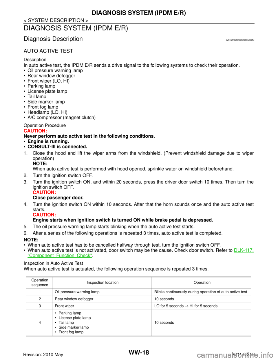
Diagnosis DescriptionINFOID:0000000006349814
AUTO ACTIVE TEST
Description
In auto active test, the IPDM E/R sends a drive signal to the following systems to check their operation.
Oil pressure warning lamp
Rear window defogger
Front wiper (LO, HI)
Parking lamp
License plate lamp
Tail lamp
Side marker lamp
Front fog lamp
Headlamp (LO, HI)
A/C compressor (magnet clutch)
Operation Procedure
CAUTION:
Never perform auto active test in the following conditions.
Engine is running.
CONSULT-III is connected.
1. Close the hood and lift the wiper arms from the windshield. (Prevent windshield damage due to wiper
operation)
NOTE:
When auto active test is performed with hood opened, sprinkle water on windshield beforehand.
2. Turn the ignition switch OFF.
3. Turn the ignition switch ON, and within 20 seconds, pr ess the driver door switch 10 times. Then turn the
ignition switch OFF.
CAUTION:
Close passenger door.
4. Turn the ignition switch ON within 10 seconds. Af ter that the horn sounds once and the auto active test
starts.
CAUTION:
Engine starts when igniti on switch is turned ON while brake pedal is depressed.
5. The oil pressure warning lamp starts blinking when the auto active test starts.
6. After a series of the following operations is repeated 3 times, auto active test is completed.
NOTE:
When auto active test has to be cancelled halfway through test, turn the ignition switch OFF.
When auto active test is not activated, door swit ch may be the cause. Check door switch. Refer to DLK-117,
"ComponentFunctionCheck".
Inspection in Auto Active Test
When auto active test is actuated, the following operation sequence is repeated 3 times.
Operation
sequence Inspection location Operation
1 Oil pressure warning lamp Blinks continuously during operation of auto active test
2 Rear window defogger 10 seconds
3 Front wiper LO for 5 seconds → HI for 5 seconds
4 Parking lamp
License plate lamp
Tail lamp
Side marker lamp
Front fog lamp 10 seconds
Revision: 2010 May2011 QX56