Page 1198 of 2057
3.Refer to: Wheel and Tire (204-04 Wheels and
Tires, Removal and Installation).
4. If equipped.
Torque: 8
Nm
E75215
5. CAUTION: Make sure that the ball joint
ball does not rotate.
Torque: 47Nm
E99103
6.Torque: 90Nm
E99108
7.Special Tool(s): 204-159, 204-605
G1000210en2008.50 Kuga8/2011
204-01- 27
Front Suspension
204-01- 27
REMOVAL AND INSTALLATION
TO MODEL INDEX
BACK TO CHAPTER INDEX
FORD KUGA 2011.0MY WORKSHOP REPAIR MANUAL
Page 1203 of 2057

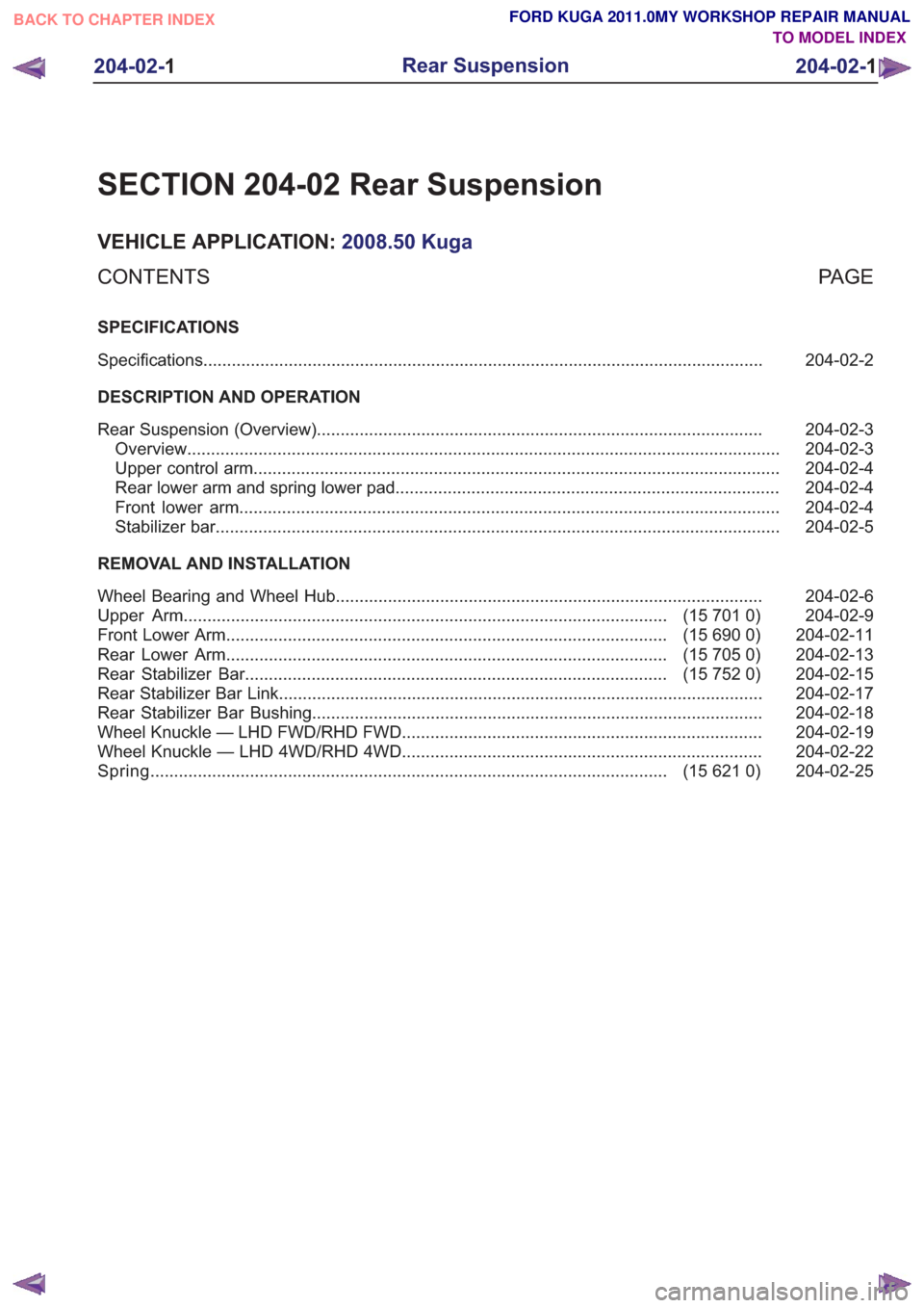
SECTION 204-02 Rear Suspension
VEHICLE APPLICATION:2008.50 Kuga
PA G E
CONTENTS
SPECIFICATIONS
204-02-2
Specifications ........................................................................\
..............................................
DESCRIPTION AND OPERATION 204-02-3
Rear Suspension (Overview) ........................................................................\
......................
204-02-3
Overview ........................................................................\
.....................................................
204-02-4
Upper control arm ........................................................................\
.......................................
204-02-4
Rear lower arm and spring lower pad ........................................................................\
.........
204-02-4
Front lower arm ........................................................................\
..........................................
204-02-5
Stabilizer bar ........................................................................\
...............................................
REMOVAL AND INSTALLATION 204-02-6
Wheel Bearing and Wheel Hub ........................................................................\
..................
204-02-9
(15 701 0)
Upper Arm ........................................................................\
..............................
204-02-11
(15 690 0)
Front Lower Arm ........................................................................\
.....................
204-02-13
(15 705 0)
Rear Lower Arm ........................................................................\
.....................
204-02-15
(15 752 0)
Rear Stabilizer Bar ........................................................................\
.................
204-02-17
Rear Stabilizer Bar Link ........................................................................\
..............................
204-02-18
Rear Stabilizer Bar Bushing ........................................................................\
.......................
204-02-19
Wheel Knuckle — LHD FWD/RHD FWD ........................................................................\
....
204-02-22
Wheel Knuckle — LHD 4WD/RHD 4WD ........................................................................\
....
204-02-25
(15 621 0)
Spring ........................................................................\
.....................................
204-02- 1
Rear Suspension
204-02- 1
.
TO MODEL INDEX
BACK TO CHAPTER INDEX
FORD KUGA 2011.0MY WORKSHOP REPAIR MANUAL
Page 1204 of 2057

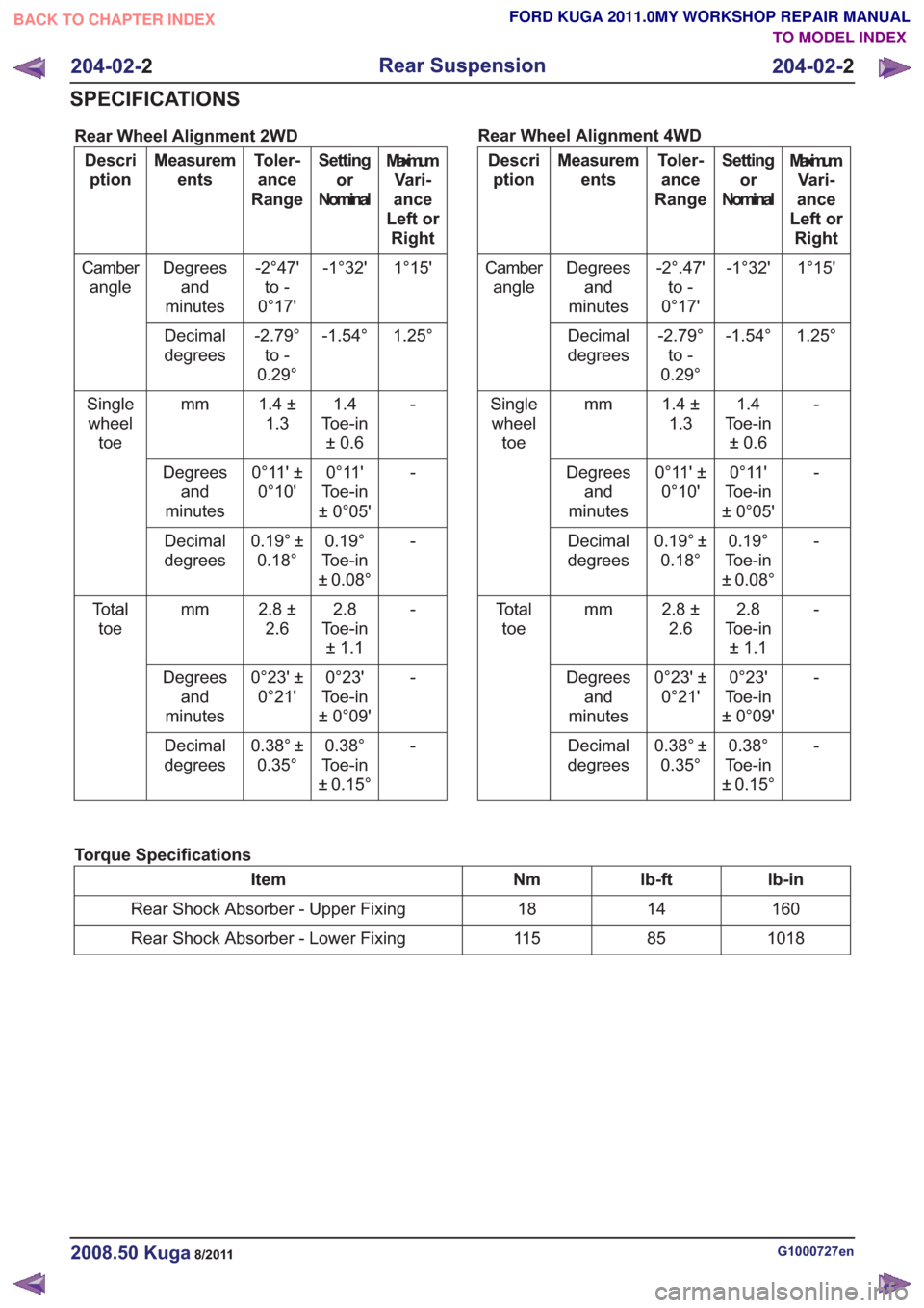
Rear Wheel Alignment 2WD
MaximumVari-
ance
Left or Right
Setting
or
Nominal
Toler-
ance
Range
Measurem
ents
Descri
ption
1°15'
-1°32'
-2°47'
to -
0°17'
Degrees
and
minutes
Camber
angle
1.25°
-1.54°
-2.79°
to -
0.29°
Decimal
degrees
-1.4
Toe-in ±0.6
1.4 ±
1.3
mm
Single
wheel toe
-
0°11'
Toe-in
± 0°05'
0°11' ±
0°10'
Degrees
and
minutes
-
0.19°
Toe-in
± 0.08°
0.19° ±
0.18°
Decimal
degrees
-2.8
Toe-in ±1.1
2.8 ±
2.6
mm
To t a l
toe
-
0°23'
Toe-in
± 0°09'
0°23' ±
0°21'
Degrees
and
minutes
-
0.38°
Toe-in
± 0.15°
0.38° ±
0.35°
Decimal
degrees Rear Wheel Alignment 4WDMaximum
Vari-
ance
Left or Right
Setting
or
Nominal
Toler-
ance
Range
Measurem
ents
Descri
ption
1°15'
-1°32'
-2°.47'
to -
0°17'
Degrees
and
minutes
Camber
angle
1.25°
-1.54°
-2.79°
to -
0.29°
Decimal
degrees
-1.4
Toe-in ±0.6
1.4 ±
1.3
mm
Single
wheel toe
-
0°11'
Toe-in
± 0°05'
0°11' ±
0°10'
Degrees
and
minutes
-
0.19°
Toe-in
± 0.08°
0.19° ±
0.18°
Decimal
degrees
-2.8
Toe-in ±1.1
2.8 ±
2.6
mm
To t a l
toe
-
0°23'
Toe-in
± 0°09'
0°23' ±
0°21'
Degrees
and
minutes
-
0.38°
Toe-in
± 0.15°
0.38° ±
0.35°
Decimal
degrees
Torque Specifications
lb-in
lb-ft
Nm
Item
160
14
18
Rear Shock Absorber - Upper Fixing
1018
85
11 5
Rear Shock Absorber - Lower Fixing
G1000727en2008.50 Kuga8/2011
204-02- 2
Rear Suspension
204-02- 2
SPECIFICATIONS
TO MODEL INDEX
BACK TO CHAPTER INDEX
FORD KUGA 2011.0MY WORKSHOP REPAIR MANUAL
Page 1205 of 2057
Rear Suspension – Overview
Overview
E98609
1
23
4
5
7
6
8
9
10
Description
Item
Subframe
1
Rear lower arm and spring lower pad
2
Spring
3
Stabilizer bar link
4
Front lower arm
5Description
Item
Wheel knuckle
6
Tie-bar
7
Shock absorber
8
Upper control arm
9
Stabilizer bar, bushings and clamps
10
G1000191en2008.50 Kuga8/2011
204-02- 3
Rear Suspension
204-02- 3
DESCRIPTION AND OPERATION
TO MODEL INDEX
BACK TO CHAPTER INDEX
FORD KUGA 2011.0MY WORKSHOP REPAIR MANUAL
Page 1208 of 2057
Wheel Bearing and Wheel Hub
Removal
NOTE:Removal steps in this procedure may
contain installation details.
1. Refer to: Wheel and Tire (204-04 Wheels and
Tires, Removal and Installation).
2. Refer to: Rear Wheel Speed Sensor (206-09
Anti-Lock Control - Stability Assist, Removal
and Installation).
3. WARNING: Make sure that no load is placed on the brake hose.
E100132
4x4
4.
E101209
5.If equipped.
E134127
All vehicles
6.
E99212
G1001323en2008.50 Kuga8/2011
204-02- 6
Rear Suspension
204-02- 6
REMOVAL AND INSTALLATION
TO MODEL INDEX
BACK TO CHAPTER INDEX
FORD KUGA 2011.0MY WORKSHOP REPAIR MANUAL
Page 1210 of 2057
5.Refer to: Rear Wheel Speed Sensor (206-09
Anti-Lock Control - Stability Assist, Removal
and Installation).
6. Refer to: Wheel and Tire (204-04 Wheels and
Tires, Removal and Installation).
4x4
7. Torque: 50Nm
E134128
8.If equipped.
E134126
G1001323en2008.50 Kuga8/2011
204-02- 8
Rear Suspension
204-02- 8
REMOVAL AND INSTALLATION
TO MODEL INDEX
BACK TO CHAPTER INDEX
FORD KUGA 2011.0MY WORKSHOP REPAIR MANUAL
Page 1211 of 2057
Upper Arm(15 701 0)
General EquipmentTransmission Jack
Removal
NOTE: Removal steps in this procedure may
contain installation details. 1.
Refer to: Wheel and Tire (204-04 Wheels and
Tires, Removal and Installation).
2. Refer to: Spring(204-02 Rear Suspension,
Removal and Installation).
3. Fabricate a spacer.
E69209
226
40
4.General Equipment: Transmission Jack
1
2
E93313
G1000224en2008.50 Kuga8/2011
204-02- 9
Rear Suspension
204-02- 9
REMOVAL AND INSTALLATION
TO MODEL INDEX
BACK TO CHAPTER INDEX
FORD KUGA 2011.0MY WORKSHOP REPAIR MANUAL
Page 1219 of 2057
Rear Stabilizer Bar Link
Removal
NOTE:Removal steps in this procedure may
contain installation details.
1. Refer to: Wheel and Tire (204-04 Wheels and
Tires, Removal and Installation).
2. CAUTION: Make sure that the ball joint ball does not rotate.
1. Torque: 70Nm
2. Torque: 15Nm
E67817
2
1
Installation
1.To install, reverse the removal procedure.
G1058286en2008.50 Kuga8/2011
204-02- 17
Rear Suspension
204-02- 17
REMOVAL AND INSTALLATION
TO MODEL INDEX
BACK TO CHAPTER INDEX
FORD KUGA 2011.0MY WORKSHOP REPAIR MANUAL