2011 FORD KUGA wheel
[x] Cancel search: wheelPage 304 of 2057

Description
Item
In-car entertainment
1
Genetic electronic module (GEM).
2
instrument cluster
3
ABS4
ABS sensor assembly
5
Rear LH mid/bass range speaker
6
Rear RH mid/bass range speaker
7
Rear LH tweeter
8 Description
Item
Rear RH tweeter
9
AUX port
10
Radio remote control.
11
FM/AM antenna
12
Front LH mid/bass speaker
13
Front RH mid/bass speaker
14
Front LH tweeter
15
Front RH tweeter
16
System Operation
In-car entertainment
The audio system is connected to the MS CAN
network and uses an internal amplifier which
directly drives the system speakers. It can only be
operated via the head unit and the radio remote
control. The head unit is connected to the vehicle
on the medium speed CAN bus. This allows the
unit to be interrogated for diagnostic purposes.
The automatic volume control (AVC) adjusts the
audio volume depending on the driving speed. The
audio device receives the necessary signals for
the ABS (anti-lock brake system) wheel sensors
from the instrument cluster on the MS-CAN. As
vehicle speed increases the audio level is adjusted
to compensate for extra road and vehicle noise.
Eight AVC settings are possible.
To choose the setting for automatic volume control,
press the MENU button until the AVC display
appears.
The required adjustment level is determined by the
Infotainment control unit based on the driving
speed signal. The vehicle speed signal is received
over the CAN. The signal is an average of the four
wheel speed sensor signals. Should an invalid
speed signal be received the AVC will not alter the
output volume.
AVC is controlled by the audio amplifier. Component Description
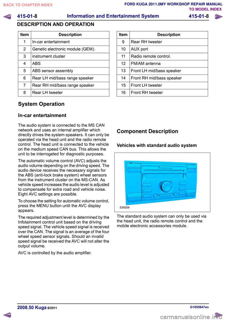
Vehicles with standard audio system
The standard audio system can only be used via
the head unit, the radio remote control and the
mobile electronic accessories module.
G1055647en
2008.50 Kuga 8/2011 415-01-8
Information and Entertainment System
415-01-8
DESCRIPTION AND OPERATIONTO MODEL INDEX
BACK TO CHAPTER INDEX
FORD KUGA 2011.0MY WORKSHOP REPAIR MANUALE99206
Page 364 of 2057

Headlamp Adjustment
General Equipment
Headlamp Beam Setter
All Vehicles
1. NOTE: Make sure that the tire pressures are to
specification and that the vehicle is unladen.
NOTE: Only use a damp cloth to clean the
headlamp lens to avoid any electrostatic
charging.
Ensure that the adjustment is made with the
suspension set up.
2. Place the vehicle on a level surface.
Vehicles with conventional headlamps
3. Repeatedly operate the headlamp leveling
switch and then set it to "0".
Vehicles with adaptive front lighting
4. Use the diagnostic tool to make certain that the
front wheels are in the straight ahead position.
Vehicles with gas discharge headlamps
5. Calibrate the headlamp leveling system using
the diagnostic tool.
All Vehicles
6. NOTE: Always follow the manufacturer's
instructions when handling the equipment.
Set the measuring screen of the beam setting
equipment to the correct headlamp adjustment
setting.
Refer to: Specifications (417-01 Exterior
Lighting, Specifications).
General Equipment: Headlamp Beam Setter
7. Switch on dipped beam. 8.
Adjust the dipped beams so that the light/dark
boundary touches the horizontal line. 9. NOTE:
It is acceptable for a stray portion of the
low beam to cross the 15° line.
Adjust the headlamps so that the rising line of
the boundary line lies at the intersection of G1066055en
2008.50 Kuga 8/2011 417-01-30
Exterior Lighting
417-01-30
GENERAL PROCEDURESTO MODEL INDEX
BACK TO CHAPTER INDEX
FORD KUGA 2011.0MY WORKSHOP REPAIR MANUALE11721715
Page 380 of 2057

Description
Item
Reversing camera module (RVC)
10
Keyless vehicle module (KVM)
11
All-wheel drive control unit
12
RDM - Driver's side
13
RCM (restraints control module)
14
DDM (driver door module)
15
Instrument Cluster
16 Description
Item
High intensity discharge headlamp module
(optional)
17
ABS (anti-lock brake system) module or
electronic stability program module
18
PCM (powertrain control module)
19
The EATC (electronic automatic
temperature control) control module
20
Electrohydraulic power steering module
21 G1072290en
2008.50 Kuga 8/2011 418-00-3
Module Communications Network
418-00-3
DESCRIPTION AND OPERATIONTO MODEL INDEX
BACK TO CHAPTER INDEX
FORD KUGA 2011.0MY WORKSHOP REPAIR MANUAL
Page 383 of 2057

Description
Item
Medium speed CAN (controller area
network) bus (MS-CAN)
A
High speed CAN bus (HS-CAN)
B
LIN (local interconnect network) bus
C
Terminating resistors
Drive
DLC (data link connector)
E
GEMRefer to Component Description: ABS
(page ?)
1
Fuel fired booster heater /programmable
fuel fired booster heater
2
The EATC control module
3
Reversing camera module (RVC)
4
Parking aid module (PAM)
5
DDM6
Front driver's side switch unit
7
Driver's side RDM
8
PDM (Passenger Door Module)
9
Passenger side RDM
10
Audio unit/navigation unit
11
CD changer
12 Description
Item
Navigation system module - vehicles
equipped with DVD navigation system with
touch screen (not communicating with the
diagnostic unit)
13
Navigation system display - vehicles
equipped with DVD navigation system with
touch screen (not communicating with the
diagnostic unit)
14
Control module for electronic auxiliary
equipment (BVC)
15
RCM16
Keyless vehicle module (KVM)
17
Instrument Cluster
18
PCM19
Fuel additive system module.
20
ABS module or electronic stability program
module
21
Yaw rate sensor/lateral acceleration
sensor
22
Headlamp Leveling Module
23
All-wheel drive control unit
24
Electrohydraulic power steering module
25
System Operation
General
In a communications network (data bus system),
various modules of different systems are connected
to one another via one or several lines.
The data bus system is used exclusively for
transmitting data between the connected modules,
as well as between the connected modules and
the Ford diagnostic unit.
In a data bus system, complete data blocks are
transmitted instead of single on/off pulses. In
addition to the actual information, these data blocks
also contain data regarding the address of the
module to be addressed, the size of the data block
and information for monitoring the content of each
individual data block.
Data bus systems offer various advantages: • Simplified data transmission between the
modules due to a standardized protocol
• Fewer sensors and connectors
• Improved diagnostic options
• Lower costs
The DLC is connected to the various data bus
systems and to the power supply via the standard
16-pin GEM. The signal for the module
programming is also transferred via the DLC.
In a data bus system, if there is a break in one or
both lines or there is a short to ground or to voltage,
then communication between the modules and
with the Ford diagnostic unit is disturbed or is no
longer possible at all.
In order to be able to establish communication with
one another, the modules of the individual systems G1030779en
2008.50 Kuga 8/2011 418-00-6
Module Communications Network
418-00-6
DESCRIPTION AND OPERATIONTO MODEL INDEX
BACK TO CHAPTER INDEX
FORD KUGA 2011.0MY WORKSHOP REPAIR MANUAL
Page 388 of 2057

Module Configuration
Activation
1.
Install the most up-to-date software version in
the integrated diagnostic system (IDS).
2. In IDS, select the "Module reprogramming"
submenu in the "Module programming" menu
tool box and then follow the instructions.
3. Transfer a new software version (if available)
to the powertrain control module (PCM) using
IDS, if a module-reprogramming of the PCM
may be required in the case of engine running
concerns.
4. Following installation of a wheel/tire
combination, for which the tire-tread
circumference does not correspond to that of
standard tires, the tire size must be changed in
the PCM using IDS. Therefore select the
"Programmable parameters" submenu and enter
the corresponding tire size under the "tire size"
menu item. G1158256en
2008.50 Kuga 8/2011 418-01-2
Module Configuration
418-01-2
GENERAL PROCEDURESTO MODEL INDEX
BACK TO CHAPTER INDEX
FORD KUGA 2011.0MY WORKSHOP REPAIR MANUAL
Page 426 of 2057

Engine Compartment Wiring Harness
Removal
NOTE:
Removal steps in this procedure may
contain installation details.
1. 2.
Refer to: Headlamp Assembly (417-01 Exterior
Lighting, Removal and Installation).
3. Refer to: Wheel and Tire (204-04 Wheels and
Tires, Removal and Installation).
4. Refer to: Fender Splash Shield (501-02 Front
End Body Panels, Removal and Installation).
5. Refer to: Front Bumper Cover (501-19 Bumpers,
Removal and Installation).
6. Torque: 10 Nm
7.
Torque: 10 Nm
G1065599en
2008.50 Kuga 8/2011 418-02-37
Wiring Harnesses
418-02-37
REMOVAL AND INSTALLATIONTO MODEL INDEX
BACK TO CHAPTER INDEX
FORD KUGA 2011.0MY WORKSHOP REPAIR MANUALE102365
Page 1158 of 2057

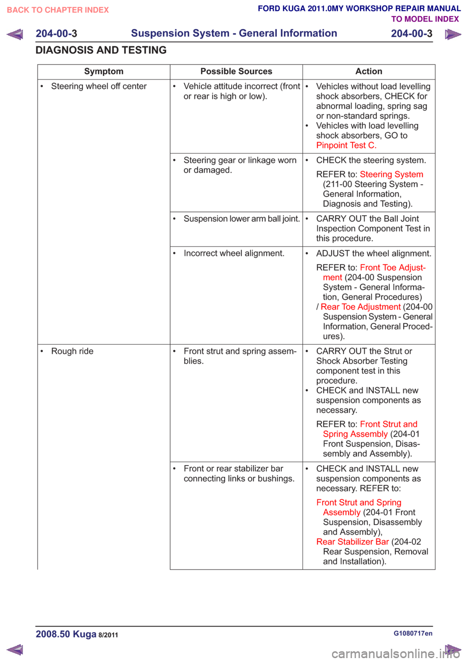
Action
Possible Sources
Symptom
• Vehicles without load levellingshock absorbers, CHECK for
abnormal loading, spring sag
or non-standard springs.
• Vehicles with load levelling shock absorbers, GO to
Pinpoint Test C.
• Vehicle attitude incorrect (front
or rear is high or low).
• Steering wheel off center
• CHECK the steering system.REFER to: Steering System
(211-00 Steering System -
General Information,
Diagnosis and Testing).
• Steering gear or linkage worn
or damaged.
• CARRY OUT the Ball JointInspection Component Test in
this procedure.
• Suspension lower arm ball joint.
• ADJUST the wheel alignment.REFER to: Front Toe Adjust-
ment (204-00 Suspension
System - General Informa-
tion, General Procedures)
/ Rear Toe Adjustment (204-00
Suspension System - General
Information, General Proced-
ures).
• Incorrect wheel alignment.
• CARRY OUT the Strut orShock Absorber Testing
component test in this
procedure.
• CHECK and INSTALL new suspension components as
necessary.
REFER to: Front Strut and
Spring Assembly (204-01
Front Suspension, Disas-
sembly and Assembly).
• Front strut and spring assem-
blies.
• Rough ride
• CHECK and INSTALL newsuspension components as
necessary. REFER to:
Front Strut and Spring Assembly (204-01 Front
Suspension, Disassembly
and Assembly),
Rear Stabilizer Bar (204-02
Rear Suspension, Removal
and Installation).
• Front or rear stabilizer bar
connecting links or bushings.
G1080717en2008.50 Kuga8/2011
204-00- 3
Suspension System - General Information
204-00- 3
DIAGNOSIS AND TESTING
TO MODEL INDEX
BACK TO CHAPTER INDEX
FORD KUGA 2011.0MY WORKSHOP REPAIR MANUAL
Page 1159 of 2057

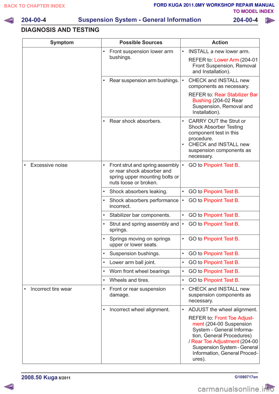
Action
Possible Sources
Symptom
• INSTALL a new lower arm.REFER to: Lower Arm (204-01
Front Suspension, Removal
and Installation).
• Front suspension lower arm
bushings.
• CHECK and INSTALL newcomponents as necessary.
REFER to: Rear Stabilizer Bar
Bushing (204-02 Rear
Suspension, Removal and
Installation).
• Rear suspension arm bushings.
• CARRY OUT the Strut orShock Absorber Testing
component test in this
procedure.
• CHECK and INSTALL new suspension components as
necessary.
• Rear shock absorbers.
• GO toPinpoint Test B.
• Front strut and spring assembly
or rear shock absorber and
spring upper mounting bolts or
nuts loose or broken.
• Excessive noise
• GO toPinpoint Test B.
• Shock absorbers leaking.
• GO toPinpoint Test B.
• Shock absorbers performance
incorrect.
• GO toPinpoint Test B.
• Stabilizer bar components.
• GO toPinpoint Test B.
• Strut and spring assembly and
springs.
• GO toPinpoint Test B.
• Springs moving on springs
upper or lower seats.
• GO toPinpoint Test B.
• Suspension bushings.
• GO toPinpoint Test B.
• Lower arm ball joint.
• GO toPinpoint Test B.
• Worn front wheel bearings
• GO toPinpoint Test B.
• Wheels and tires.
• CHECK and INSTALL newsuspension components as
necessary.
• Front or rear suspension
damage.
• Incorrect tire wear
• ADJUST the wheel alignment.REFER to: Front Toe Adjust-
ment (204-00 Suspension
System - General Informa-
tion, General Procedures)
/ Rear Toe Adjustment (204-00
Suspension System - General
Information, General Proced-
ures).
• Incorrect wheel alignment.
G1080717en2008.50 Kuga8/2011
204-00-
4
Suspension System - General Information
204-00- 4
DIAGNOSIS AND TESTING
TO MODEL INDEX
BACK TO CHAPTER INDEX
FORD KUGA 2011.0MY WORKSHOP REPAIR MANUAL