Page 1260 of 2057
1
2
3
4
E115887
Description
Item
Fluid filter
1
All-wheel drive control unit
2Description
Item
Electric feed pump
3
Pressure accumulator
4
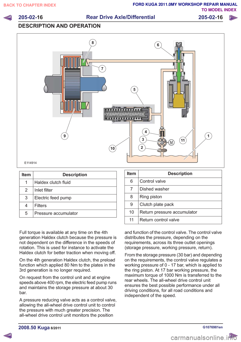
The electric feed pump is an axial piston pump
which is more robustly designed than the gerotor
pump in the 3rd generation Haldex. The higher
feed pressure means that the ring piston pump at
the clutch plate assembly, the pressure relief
valves, preload valve and the high pressure valves
are no longer necessary.
The pressure accumulator on the 4th generation
Haldex is larger and is designed for the higher
pressure. The 4th generation Haldex has a larger fluid filter
which contains a non-return valve.
The all-wheel drive control unit no longer contains
a pressure sensor in the 4th generation Haldex.
Pressure control - 4th generation Haldex
clutch
G1076981en2008.50 Kuga8/2011
205-02-
15
Rear Drive Axle/Differential
205-02- 15
DESCRIPTION AND OPERATION
TO MODEL INDEX
BACK TO CHAPTER INDEX
FORD KUGA 2011.0MY WORKSHOP REPAIR MANUAL
Page 1261 of 2057

6
7
8
9
10
11
1
2
3
4
5
6
7
8
9
10
11
E114914
Description
Item
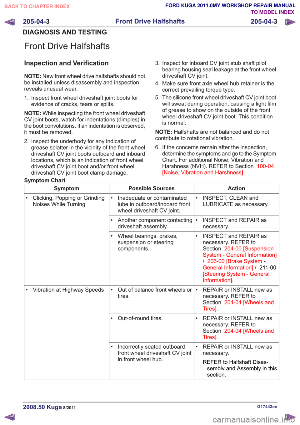
Haldex clutch fluid
1
Inlet filter
2
Electric feed pump
3
Filters4
Pressure accumulator
5Description
Item
Control valve
6
Dished washer
7
Ring piston
8
Clutch plate pack
9
Return pressure accumulator
10
Return control valve
11
Full torque is available at any time on the 4th
generation Haldex clutch because the pressure is
not dependent on the difference in the speeds of
rotation. This is used for instance to activate the
Haldex clutch for better traction when moving off.
On the 4th generation Haldex clutch, the preload
function which applied 80 Nm to the plates in the
3rd generation is no longer required.
On request from the control unit and at engine
speeds above 400 rpm, the electric feed pump runs
and maintains the storage pressure at about 30
bar.
A pressure reducing valve acts as a control valve,
allowing the all-wheel drive control unit to control
the pressure with much greater precision. The
all-wheel drive control unit monitors the position and function of the control valve. The control valve
distributes the pressure, depending on the
requirements, across its three outlet openings
(storage pressure, working pressure, return).
From the storage pressure (30 bar) and depending
on the requirements, the control valve regulates a
working pressure of 0 - 17 bar, which is applied to
the ring piston. At 17 bar working pressure, the
maximum torque of 1000 Nm is transferred to the
rear wheels. The all-wheel drive control unit
ensures the best possible performance under all
driving conditions, for all road conditions and
independent of the speed.
G1076981en2008.50 Kuga8/2011
205-02-
16
Rear Drive Axle/Differential
205-02- 16
DESCRIPTION AND OPERATION
TO MODEL INDEX
BACK TO CHAPTER INDEX
FORD KUGA 2011.0MY WORKSHOP REPAIR MANUAL
Page 1298 of 2057

Front Drive Halfshafts
Inspection and Verification
NOTE:New front wheel drive halfshafts should not
be installed unless disassembly and inspection
reveals unusual wear.
1. Inspect front wheel driveshaft joint boots for evidence of cracks, tears or splits.
NOTE: While inspecting the front wheel driveshaft
CV joint boots, watch for indentations (dimples) in
the boot convolutions. If an indentation is observed,
it must be removed.
2. Inspect the underbody for any indication of grease splatter in the vicinity of the front wheel
driveshaft CV joint boots outboard and inboard
locations, which is an indication of front wheel
driveshaft CV joint boot and/or front wheel
driveshaft CV joint boot clamp damage. 3. Inspect for inboard CV joint stub shaft pilot
bearing housing seal leakage at the front wheel
driveshaft CV joint.
4. Make sure front axle wheel hub retainer is the correct prevailing torque type.
5. The silicone front wheel driveshaft CV joint boot will sweat during operation, causing a light film
of grease to show on the outside of the front
wheel driveshaft CV joint boot. This condition
is normal.
NOTE: Halfshafts are not balanced and do not
contribute to rotational vibration.
6. If the concerns remain after the inspection, determine the symptoms and go to the Symptom
Chart. For additional Noise, Vibration and
Harshness (NVH). REFER to Section 100-04
[Noise, Vibration and Harshness] .
Symptom Chart
Action
Possible Sources
Symptom
• INSPECT, CLEAN andLUBRICATE as necessary.
• Inadequate or contaminated
lube in outboard/inboard front
wheel driveshaft CV joint.
• Clicking, Popping or Grinding
Noises While Turning
• INSPECT and REPAIR asnecessary.
• Another component contacting
driveshaft assembly.
• INSPECT and REPAIR asnecessary. REFER to
Section 204-00 [Suspension
System - General Information]
/ 206-00 [Brake System -
General Information] /211-00
[Steering System - General
Information] .
• Wheel bearings, brakes,
suspension or steering
components.
• REPAIR or INSTALL new asnecessary. REFER to
Section 204-04 [Wheels and
Tires] .
• Out of balance front wheels or
tires.
• Vibration at Highway Speeds
• REPAIR or INSTALL new asnecessary. REFER to
Section 204-04 [Wheels and
Tires] .
• Out-of-round tires.
• REPAIR or INSTALL new asnecessary.
REFER to Halfshaft Disas-
semblv and Assembly in this
section.
• Incorrectly seated outboard
front wheel driveshaft CV joint
in front wheel hub.
G17442en2008.50 Kuga8/2011
205-04- 3
Front Drive Halfshafts
205-04- 3
DIAGNOSIS AND TESTING
TO MODEL INDEX
BACK TO CHAPTER INDEX
FORD KUGA 2011.0MY WORKSHOP REPAIR MANUAL
Page 1299 of 2057

Action
Possible Sources
Symptom
• CHECK ride height, VERIFYcorrect spring rate and CHECK
items under Halfshaft Joint
Pullout. REPAIR or INSTALL
new as necessary.
• Excessively high CV joint oper-
ating angles caused by incor-
rect ride height.
• Shudder Vibration During
Acceleration.
• INSPECT and INSTALL newas necessary.
• Excessively worn or damaged
inboard front wheel driveshaft
joint or outboard front wheel
driveshaft joint.
• INSPECT and REPAIR orINSTALL new as necessary.
• Inboard driveshaft bearing
retainer circlip missing or not
correctly seated in differential
side gear.
• Halfshaft Joint Pullout
• CHECK engine mounts fordamage or wear. REPAIR or
INSTALL new as necessary.
• Engine/transaxle assembly
mispositioned.
• CHECK underbody dimensions.REFER to REFER to
Section 501-00 [Body System
-General Information] .
• Frame rail or strut tower out of
position or damaged.
• CHECK for worn bushings orbent components (front stabil-
izer bar, front suspension lower
arm). REPAIR or INSTALL new
as necessary.
• Front suspension components
worn or damaged.
G17442en2008.50 Kuga8/2011
205-04- 4
Front Drive Halfshafts
205-04- 4
DIAGNOSIS AND TESTING
TO MODEL INDEX
BACK TO CHAPTER INDEX
FORD KUGA 2011.0MY WORKSHOP REPAIR MANUAL
Page 1300 of 2057
Front Halfshaft LH(14 320 0)
Special Tool(s) / General Equipment204-159
Lever, Wheel Knuckle
14039
204-602
Installer, Halfshaft
E62067
204-605
Separator, Lower Arm Ball
Joint
E63772
204-609
Protection Cap, Ball Joint
Gaiter
E75372
205-071-01
Adapter for 205-071 (Thrust
Pad)
15026A01
205-775
Protector, Halfshaft Seal
E47098
Special Tool(s) / General Equipment211-020
Separator, Ball Joint
13006
308-782
Remover, Driveline
E115823
Puller
Tire Lever
Removal
1. NOTE:This step is only necessary when
installing a new component.
E99184
G1076961en2008.50 Kuga8/2011
205-04- 5
Front Drive Halfshafts
205-04- 5
REMOVAL AND INSTALLATION
TO MODEL INDEX
BACK TO CHAPTER INDEX
FORD KUGA 2011.0MY WORKSHOP REPAIR MANUAL
Page 1301 of 2057
2.Refer to: Lifting(100-02 Jacking and Lifting,
Description and Operation).
Refer to: Wheel and Tire (204-04 Wheels and
Tires, Removal and Installation).
3. NOTE: This step is only necessary when
installing a new component.
E99269
4.
E101039
5. WARNING: Make sure that no load is placed on the brake hose.
E100801
G1076961en2008.50 Kuga8/2011
205-04- 6
Front Drive Halfshafts
205-04- 6
REMOVAL AND INSTALLATION
TO MODEL INDEX
BACK TO CHAPTER INDEX
FORD KUGA 2011.0MY WORKSHOP REPAIR MANUAL
Page 1310 of 2057
13.
E67589
14.Torque: 120Nm
x2x2
E132307
15.
E101039
16.
17.If equipped.
E98543
x7
18.Refer to: Wheel and Tire (204-04 Wheels and
Tires, Removal and Installation).
19. Lower the Vehicle.
20. N O T E : This step is only necessary when
installing a new component.
Torque: 270
Nm
E99195
G1076961en2008.50 Kuga8/2011
205-04- 15
Front Drive Halfshafts
205-04- 15
REMOVAL AND INSTALLATION
TO MODEL INDEX
BACK TO CHAPTER INDEX
FORD KUGA 2011.0MY WORKSHOP REPAIR MANUAL
Page 1311 of 2057
Front Halfshaft RH — LHD 4WD/RHD 4WD(14 321 0)
Special Tool(s) / General Equipment204-159
Lever, Wheel Knuckle
14039
204-602
Installer, Halfshaft
E62067
204-605
Separator, Lower Arm Ball
Joint
E63772
204-609
Protection Cap, Ball Joint
Gaiter
E75372
205-071-01
Adapter for 205-071 (Thrust
Pad)
15026A01
211-020
Separator, Ball Joint
13006
Puller
Removal
1. NOTE:This step is only necessary when
installing a new component.
E99184
2. Refer to: Lifting(100-02 Jacking and Lifting,
Description and Operation).
Refer to: Wheel and Tire (204-04 Wheels and
Tires, Removal and Installation).
3. NOTE: This step is only necessary when
installing a new component.
E102112
G1076962en2008.50 Kuga8/2011
205-04- 16
Front Drive Halfshafts
205-04- 16
REMOVAL AND INSTALLATION
TO MODEL INDEX
BACK TO CHAPTER INDEX
FORD KUGA 2011.0MY WORKSHOP REPAIR MANUAL