Page 1802 of 2057
voltage signal to the PCM corresponding to the
aspirated air mass.
This analogue voltage signal is between 0.5V and
5V. Low mass of intake air produces a low voltage
signal. A high mass of intake air produces a
correspondingly high voltage signal.
The MAF sensor is also capable of detecting the
backflow of the intake air. A sensor element is
heated electrically on the integrated chip and then
cooled by the air flowing through. The regulating
switch supplies the heating current in such a way
that it attains a constant excess temperature in
comparison to the intake air. The mass air flow and
the direction of flow can be derived from this
heating current (given in the form of a signal
voltage). Below a certain voltage value there is a
return flow. The direction is flow is registered by
two sensors pointing in different directions. The
measurement does not require a great deal of
software processing effort, even with a strongly
pulsating mass air flow.MAPT
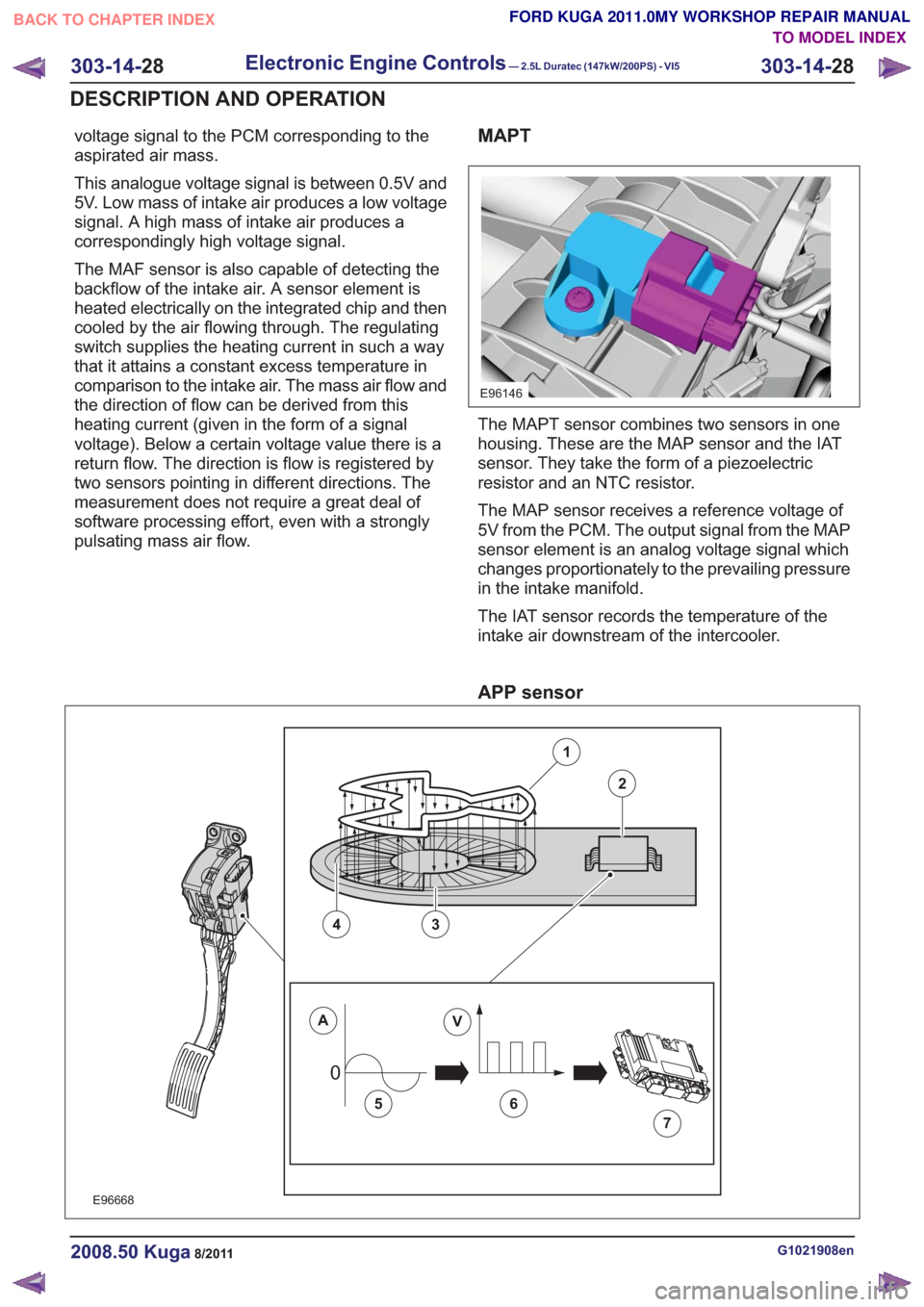
E96146
The MAPT sensor combines two sensors in one
housing. These are the MAP sensor and the IAT
sensor. They take the form of a piezoelectric
resistor and an NTC resistor.
The MAP sensor receives a reference voltage of
5V from the PCM. The output signal from the MAP
sensor element is an analog voltage signal which
changes proportionately to the prevailing pressure
in the intake manifold.
The IAT sensor records the temperature of the
intake air downstream of the intercooler.
APP sensor
00
E96668
1
2
43
AV
56
7
G1021908en2008.50 Kuga8/2011
303-14-28
Electronic Engine Controls— 2.5L Duratec (147kW/200PS) - VI5303-14-
28
DESCRIPTION AND OPERATION
TO MODEL INDEX
BACK TO CHAPTER INDEX
FORD KUGA 2011.0MY WORKSHOP REPAIR MANUAL
Page 1835 of 2057
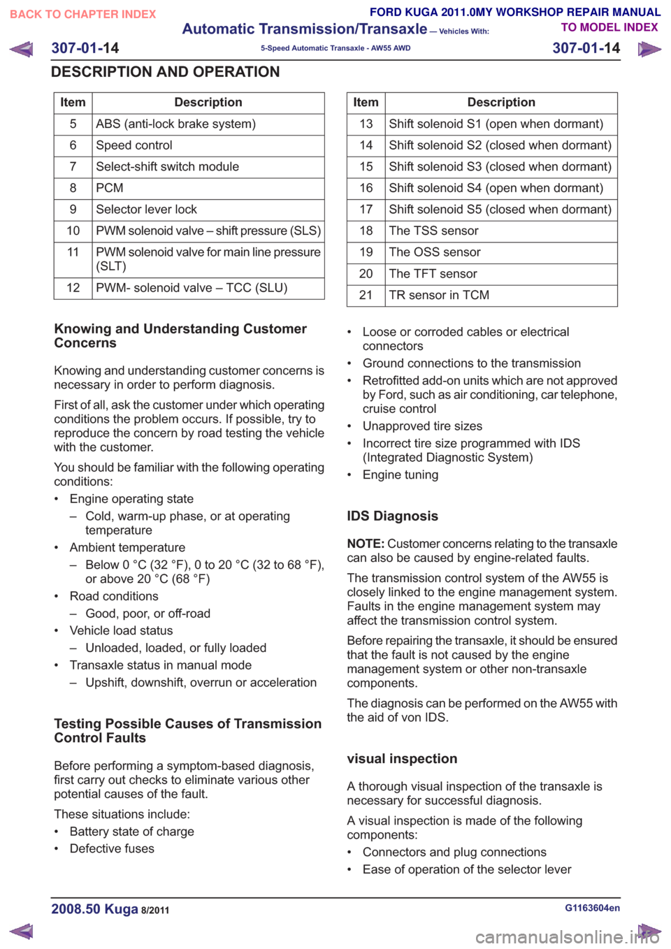
Description
Item
ABS (anti-lock brake system)
5
Speed control
6
Select-shift switch module
7
PCM
8
Selector lever lock
9
PWM solenoid valve – shift pressure (SLS)
10
PWM solenoid valve for main line pressure
(SLT)
11
PWM- solenoid valve – TCC (SLU)
12Description
Item
Shift solenoid S1 (open when dormant)
13
Shift solenoid S2 (closed when dormant)
14
Shift solenoid S3 (closed when dormant)
15
Shift solenoid S4 (open when dormant)
16
Shift solenoid S5 (closed when dormant)
17
The TSS sensor
18
The OSS sensor
19
The TFT sensor
20
TR sensor in TCM
21
Knowing and Understanding Customer
Concerns
Knowing and understanding customer concerns is
necessary in order to perform diagnosis.
First of all, ask the customer under which operating
conditions the problem occurs. If possible, try to
reproduce the concern by road testing the vehicle
with the customer.
You should be familiar with the following operating
conditions:
• Engine operating state
– Cold, warm-up phase, or at operatingtemperature
• Ambient temperature – Below 0 °C (32 °F), 0 to 20 °C (32 to 68 °F),or above 20 °C (68 °F)
• Road conditions – Good, poor, or off-road
• Vehicle load status – Unloaded, loaded, or fully loaded
• Transaxle status in manual mode – Upshift, downshift, overrun or acceleration
Testing Possible Causes of Transmission
Control Faults
Before performing a symptom-based diagnosis,
first carry out checks to eliminate various other
potential causes of the fault.
These situations include:
• Battery state of charge
• Defective fuses • Loose or corroded cables or electrical
connectors
• Ground connections to the transmission
• Retrofitted add-on units which are not approved by Ford, such as air conditioning, car telephone,
cruise control
• Unapproved tire sizes
• Incorrect tire size programmed with IDS (Integrated Diagnostic System)
• Engine tuning
IDS Diagnosis
NOTE: Customer concerns relating to the transaxle
can also be caused by engine-related faults.
The transmission control system of the AW55 is
closely linked to the engine management system.
Faults in the engine management system may
affect the transmission control system.
Before repairing the transaxle, it should be ensured
that the fault is not caused by the engine
management system or other non-transaxle
components.
The diagnosis can be performed on the AW55 with
the aid of von IDS.
visual inspection
A thorough visual inspection of the transaxle is
necessary for successful diagnosis.
A visual inspection is made of the following
components:
• Connectors and plug connections
• Ease of operation of the selector lever
G1163604en2008.50 Kuga8/2011
307-01- 14
Automatic Transmission/Transaxle
— Vehicles With:
5-Speed Automatic Transaxle - AW55 AWD
307-01- 14
DESCRIPTION AND OPERATION
TO MODEL INDEX
BACK TO CHAPTER INDEX
FORD KUGA 2011.0MY WORKSHOP REPAIR MANUAL
Page 1846 of 2057
Serial number of the transmission
Example:09HV70001
• 09: year of manufacture, 2009 •
H: code letter for the month of manufacture,
August
• V7: automatic transaxle type 55-51SN
• 00001 : Production number for the specified
month
Identification letter coding
January
A
February
B
March
C
April
D
May
E
June
F
July
G
August
H.
September
J
October
K
November
left-hand
December
Ground
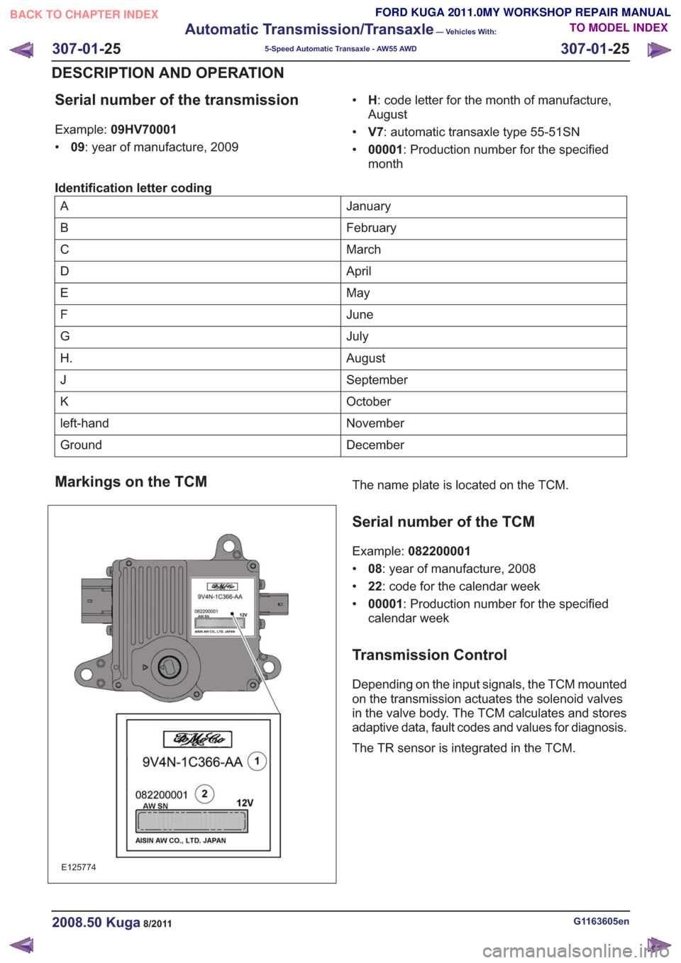
Markings on the TCM
E125774
The name plate is located on the TCM.
Serial number of the TCM
Example: 082200001
• 08: year of manufacture, 2008
• 22: code for the calendar week
• 00001 : Production number for the specified
calendar week
Transmission Control
Depending on the input signals, the TCM mounted
on the transmission actuates the solenoid valves
in the valve body. The TCM calculates and stores
adaptive data, fault codes and values for diagnosis.
The TR sensor is integrated in the TCM.
G1163605en2008.50 Kuga8/2011
307-01- 25
Automatic Transmission/Transaxle
— Vehicles With:
5-Speed Automatic Transaxle - AW55 AWD
307-01- 25
DESCRIPTION AND OPERATION
TO MODEL INDEX
BACK TO CHAPTER INDEX
FORD KUGA 2011.0MY WORKSHOP REPAIR MANUAL
Page 1881 of 2057
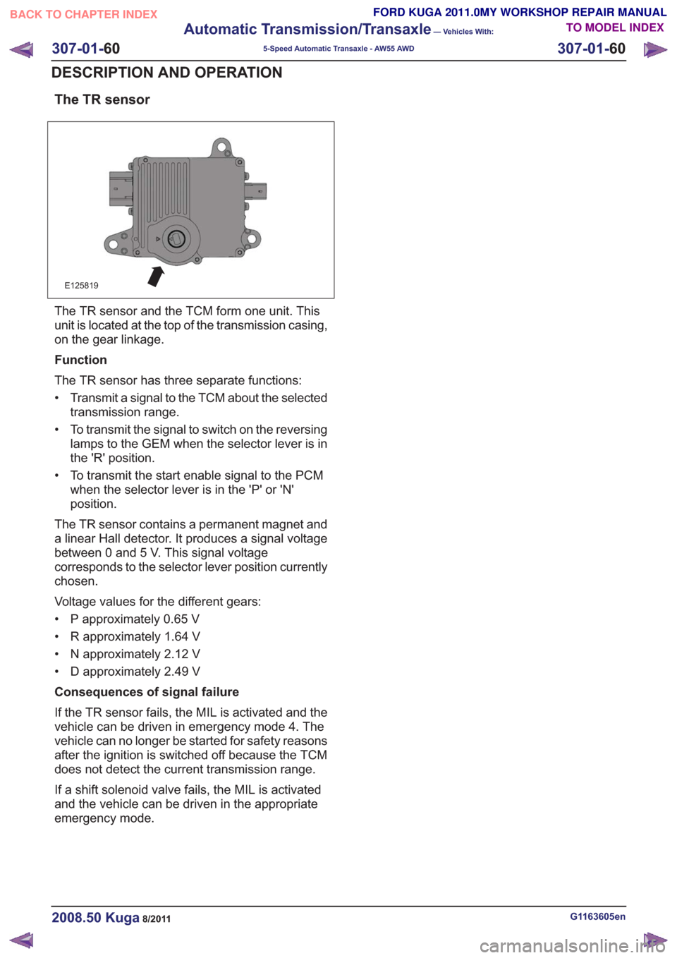
The TR sensor
E125819
The TR sensor and the TCM form one unit. This
unit is located at the top of the transmission casing,
on the gear linkage.
Function
The TR sensor has three separate functions:
• Transmit a signal to the TCM about the selectedtransmission range.
• To transmit the signal to switch on the reversing lamps to the GEM when the selector lever is in
the 'R' position.
• To transmit the start enable signal to the PCM when the selector lever is in the 'P' or 'N'
position.
The TR sensor contains a permanent magnet and
a linear Hall detector. It produces a signal voltage
between 0 and 5 V. This signal voltage
corresponds to the selector lever position currently
chosen.
Voltage values for the different gears:
• P approximately 0.65 V
• R approximately 1.64 V
• N approximately 2.12 V
• D approximately 2.49 V
Consequences of signal failure
If the TR sensor fails, the MIL is activated and the
vehicle can be driven in emergency mode 4. The
vehicle can no longer be started for safety reasons
after the ignition is switched off because the TCM
does not detect the current transmission range.
If a shift solenoid valve fails, the MIL is activated
and the vehicle can be driven in the appropriate
emergency mode.
G1163605en2008.50 Kuga8/2011
307-01- 60
Automatic Transmission/Transaxle
— Vehicles With:
5-Speed Automatic Transaxle - AW55 AWD
307-01- 60
DESCRIPTION AND OPERATION
TO MODEL INDEX
BACK TO CHAPTER INDEX
FORD KUGA 2011.0MY WORKSHOP REPAIR MANUAL
Page 1950 of 2057
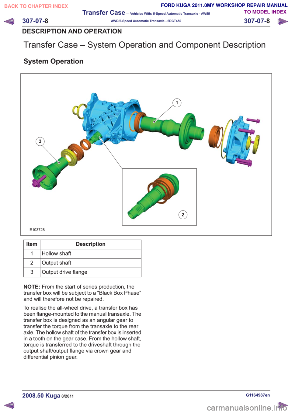
Transfer Case – System Operation and Component Description
System Operation
1
2
3
E103728
Description
Item
Hollow shaft
1
Output shaft
2
Output drive flange
3
NOTE: From the start of series production, the
transfer box will be subject to a "Black Box Phase"
and will therefore not be repaired.
To realise the all-wheel drive, a transfer box has
been flange-mounted to the manual transaxle. The
transfer box is designed as an angular gear to
transfer the torque from the transaxle to the rear
axle. The hollow shaft of the transfer box is inserted
in a tooth on the gear case. From the hollow shaft,
torque is transferred to the driveshaft through the
output shaft/output flange via crown gear and
differential pinion gear.
G1164987en2008.50 Kuga8/2011
307-07- 8
Transfer Case
— Vehicles With: 5-Speed Automatic Transaxle - AW55
AWD/6-Speed Automatic Transaxle - 6DCT450
307-07- 8
DESCRIPTION AND OPERATION
TO MODEL INDEX
BACK TO CHAPTER INDEX
FORD KUGA 2011.0MY WORKSHOP REPAIR MANUAL
Page 2010 of 2057
Speed Control
Inspection and Verification
1. Verify the customer concern by operating thesystem.
2. Visually inspect for obvious signs of mechanical or electrical damage.
Visual Inspection Chart
Electrical
Mechanical
– Fuse(s)
– Connections
– Wiring harness
– Clockspring
– Loose or corrodedelectrical
connector(s)
– Speed control switch
– Brake pedal position (BPP) deactivation
switch
– Clutch pedal posi- tion (CPP) deactiva-
tion Switch
– Powertrain control module (PCM)
– Central junction box (CJB)
– Brake pedal
– Clutch pedal
3. NOTE: Not all passenger junction box (PJB) variants support the speed control system.
NOTE: If the PJB is configured for speed control
disable, speed control operation is not transmitted,
no Diagnostic Trouble Codes (DTCs) are
generated.
If an obvious cause for an observed or reported
concern is found, correct the cause (if possible)
before proceeding to the next step.
4. If the cause is not visually evident, verify the symptom and refer to the diagnostic tab within
the Ford approved diagnostic tool.
G1054908en2008.50 Kuga8/2011
310-03- 7
Speed Control
310-03- 7
DIAGNOSIS AND TESTING
TO MODEL INDEX
BACK TO CHAPTER INDEX
FORD KUGA 2011.0MY WORKSHOP REPAIR MANUAL
Page 2026 of 2057
Fluorescent Dye Leak Detection
General EquipmentUV Leak Detector
1. Refer to: Air Conditioning (A/C) System Health
and Safety Precautions (100-00 General
Information, Description and Operation).
2. NOTE: Some vehicles may have signs of
refrigerant oil at the spring lock couplers. The
cause of this may be a procedure used in
production before installation of the fittings in
order to assist their assembly. When a spring
lock coupler is suspected of leaking, always
wipe the fitting clean and verify the leak with
R-134a Automatic Calibration Halogen Leak
Detector.
NOTE: The exact location of leaks can be
pinpointed by the bright yellow - green glow of
the tracer dye. Since more than one leak can
exist, always inspect each component.
• Locate the leaks. Check all components, fittings and lines of the A/C system for leaks.
General Equipment: UV Leak Detector
3. After the leak is found and rectified, remove any
traces of dye with a general purpose solvent.
4. Check the repair by operating the system for
some minutes and inspecting with the UV lamp
again.
G1065493en2008.50 Kuga8/2011
412-00- 15
Climate Control System - General Information
412-00- 15
GENERAL PROCEDURES
TO MODEL INDEX
BACK TO CHAPTER INDEX
FORD KUGA 2011.0MY WORKSHOP REPAIR MANUAL
Page 2035 of 2057
Climate control housing - vehicles with manual temperature control
E97588
1
7
3
862
4
9
5
Description
Item
Air flap actuator
1
Control unit - air distribution
flap/temperature control flap
2
Operating lever - temperature control flap
3
Operating lever - air distribution flap -
footwell
4Description
Item
Operating lever - air distribution flap -
central nozzles
5
Operating lever - air distribution flap -
demister vents
6
Rod - air distribution flap
7
Operating cable - temperature control flap
8
Blower motor resistor
9
G1034943en2008.50 Kuga8/2011
412-01- 8
Climate Control
412-01- 8
DESCRIPTION AND OPERATION
TO MODEL INDEX
BACK TO CHAPTER INDEX
FORD KUGA 2011.0MY WORKSHOP REPAIR MANUAL