2011 FORD KUGA rod
[x] Cancel search: rodPage 263 of 2057
Charging System
Refer to Wiring Diagrams Section 414-02, for
schematic and connector information.
General Equipment
Midtronics EXP-1050 battery tester
Midtronics GR590-2
Ford diagnostic equipment
Inspection and Verification
WARNINGS: Batteries contain sulphuric acid. Avoid
contact with skin, eyes, or clothing. Also,
shield your eyes when working near
batteries to protect against possible
splashing of the acid solution. In case of
acid contact with skin or eyes, flush
immediately with water for a minimum of
15 minutes and get prompt medical
attention. If acid is swallowed, call a
physician immediately. Failure to follow
these instructions may result in personal
injury.
Batteries normally produce explosive
gases which can cause personal injury.
Therefore, do not allow flames, sparks or
lighted substances to come near the
battery. When charging or working near a
battery, always shield your face and
protect your eyes. Always provide
ventilation. Failure to follow these
instructions may result in personal injury.
1. Verify the customer concern.
2. Visually inspect for obvious signs of mechanical
or electrical damage.
Visual Inspection Chart Electrical
Mechanical
– Fuse(s)
– Wiring harness(es)
– Generator
– Electricalconnector(s)
– Battery junction box (BJB)
– Battery
– Battery cables
– Battery monitoring sensor (BMS)
– Charging system warning indicator
–
Accessory drive belt
– Generator
3. If an obvious cause for an observed or reported concern is found, correct the cause (if possible)
before proceeding to the next step.
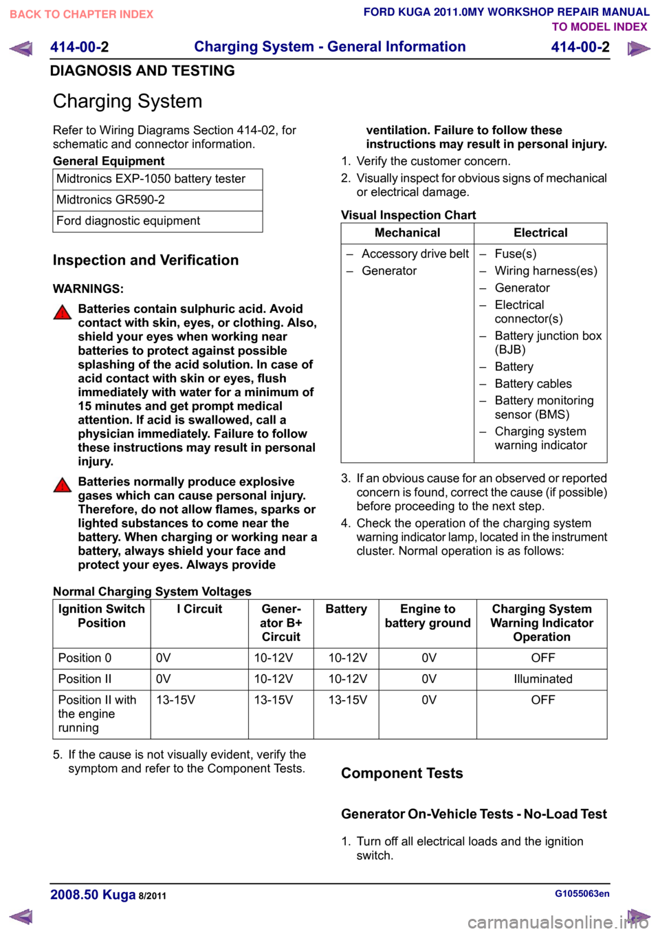
4. Check the operation of the charging system warning indicator lamp, located in the instrument
cluster. Normal operation is as follows:
Normal Charging System Voltages Charging System
Warning Indicator Operation
Engine to
battery ground
Battery
Gener-
ator B+ Circuit
I Circuit
Ignition Switch
Position
OFF
0V
10-12V
10-12V
0V
Position 0
Illuminated
0V
10-12V
10-12V
0V
Position II
OFF
0V
13-15V
13-15V
13-15V
Position II with
the engine
running
5. If the cause is not visually evident, verify the symptom and refer to the Component Tests. Component Tests
Generator On-Vehicle Tests - No-Load Test
1. Turn off all electrical loads and the ignition
switch. G1055063en
2008.50 Kuga 8/2011 414-00-2
Charging System - General Information
414-00-2
DIAGNOSIS AND TESTINGTO MODEL INDEX
BACK TO CHAPTER INDEX
FORD KUGA 2011.0MY WORKSHOP REPAIR MANUAL
Page 270 of 2057

Battery Disconnect and Connect
Disconnect
WARNINGS:
Batteries normally produce explosive
gases which may cause personal injury,
therefore do not allow flames, sparks or
lighted substances to come near the
battery. When charging or working near
the battery always shield your face and
protect your eyes. Always provide
adequate ventilation. Failure to follow
these instructions may result in personal
injury.
The supplemental restraint system (SRS)
is active for a certain length of time after
the power supply has been disconnected.
Wait for a minimum of 3 minutes before
disconnecting or removing any SRS
components.
Audio unit key code saving devices must
not be used when working on
supplemental restraint or fuel systems.
When using these devices the vehicle
electrical system is still live but with a
reduced current flow. Failure to follow this
instruction may result in personal injury.
CAUTION: Make sure the engine is not
running before disconnecting the battery
ground cable to avoid damage to the
vehicle electrical system.
NOTE: Disconnecting the battery will erase fault
codes, drive values and customer data stored in
the modules.
NOTE: This procedure should be used to
disconnect the battery while carrying out repairs
that refer to the battery being disconnected.
1. Refer to: Battery and Battery Charging Health
and Safety Precautions (100-00 General
Information, Description and Operation).
2. Obtain and record the audio unit keycode and
preset radio frequencies. 3.
G1062389en
2008.50 Kuga 8/2011 414-01-2
Battery, Mounting and Cables
414-01-2
GENERAL PROCEDURESTO MODEL INDEX
BACK TO CHAPTER INDEX
FORD KUGA 2011.0MY WORKSHOP REPAIR MANUALE103137
Page 305 of 2057
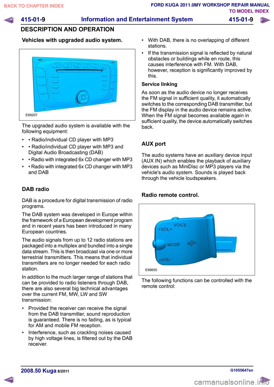
Vehicles with upgraded audio system.
The upgraded audio system is available with the
following equipment:
• • Radio/individual CD player with MP3
• • Radio/individual CD player with MP3 and
Digital Audio Broadcasting (DAB)
• • Radio with integrated 6x CD changer with MP3
• • Radio with integrated 6x CD changer with MP3
and DAB
DAB radio
DAB is a procedure for digital transmission of radio
programs.
The DAB system was developed in Europe within
the framework of a European development program
and in recent years has been introduced in many
European countries.
The audio signals from up to 12 radio stations are
packaged into a multiplex and bundled into a single
data stream. This is then broadcast via one or more
terrestrial transmitters. This means that individual
transmitters are no longer needed for each radio
station.
In addition to the much larger range of stations that
can be provided to radio listeners through DAB,
there are also several big technical advantages
over the current FM, MW, LW and SW
transmission:
• Provided the receiver can receive the signal from the DAB transmitter, sound reproduction
is guaranteed. There is no fading, as is typical
for AM and mobile FM reception.
• Interference, such as crackling noises caused by high voltage lines, is filtered out by the DAB
receiver. • With DAB, there is no overlapping of different
stations.
• If the transmission signal is reflected by natural obstacles or buildings while en route, this
causes interference with FM. With DAB,
however, reception is significantly improved by
this.
Service linking
As soon as the audio device no longer receives
the FM signal in sufficient quality, it automatically
switches to the corresponding DAB transmitter, but
the FM display in the audio device remains active.
When the FM signal becomes available again in
sufficient quality, the device automatically switches
back.
AUX port
The audio systems have an auxiliary device input
(AUX IN) which enables the playback of auxiliary
devices such as MiniDisc or MP3 players via the
vehicle's audio system. Sounds is played back
through the vehicle loudspeakers.
Radio remote control. The following functions can be controlled with the
remote control:
G1055647en
2008.50 Kuga 8/2011 415-01-9
Information and Entertainment System
415-01-9
DESCRIPTION AND OPERATIONTO MODEL INDEX
BACK TO CHAPTER INDEX
FORD KUGA 2011.0MY WORKSHOP REPAIR MANUALE99207 E98650
Page 340 of 2057

The turn signal lamps and side lights are the same as in conventional headlamps.
Bulb color
Current draw
Bulb
Lamp
Clear
35W
D1S
Low-beams
Clear
55W
H1
High beam headlamp
Clear
21W
H21W
Turn signal indicator
Clear
5W
W5W
Side lamp
Headlamp levelling
Vehicles with conventional headlamps are
equipped with a manual headlamp leveling system. An automatic headlamp leveling system is a legal
requirement for vehicles with gas discharge
headlamps.
The automatic headlamp levelling system is a
dynamic system which provides additional benefits
for the driver in terms of improved illumination of
the road due to improved control over the
headlamp beam.
In a static system, the vehicle is only considered
as a stationary object, whereas a dynamic system
also takes into account the dynamic changes to
the inclination of the vehicle whilst driving.
In order to prevent unnecessary changes in the
height of the headlamp beam, the system filters
out surface irregularities and any pitching of the
vehicle under braking and acceleration.
The system is designed to respond to changes in
the inclination of the vehicle caused by load
changes or long-term effects of aerodynamic forces
acting on the vehicle (e.g. due to continuous driving
at high speeds).
Accordingly, the system needs to be set up with
the aid of WDS (Worldwide Diagnostic System)
after any components are replaced or any other
repairs are carried out.
G1079626en
2008.50 Kuga 8/2011 417-01-6
Exterior Lighting
417-01-6
DESCRIPTION AND OPERATIONTO MODEL INDEX
BACK TO CHAPTER INDEX
FORD KUGA 2011.0MY WORKSHOP REPAIR MANUALE101614
Page 1168 of 2057
3. If a new lower arm is installed it will benecessary to check and adjust the front wheel
alignment.
REFER to: Front Toe Adjustment (204-00
Suspension System - General Information,
General Procedures)
/ Rear Toe Adjustment (204-00 Suspension
System - General Information, General
Procedures).
Strut or Shock Absorber Inspection
NOTE: Inspect the struts or shock absorber for
signs of oil weepage or leaks. Make sure that the
oil is not from another source.
Weepage:
• deposits a thin film of oil on the strut and spring assembly or shock absorber.
• is normally noticed due to a collection of dust on the strut and spring assembly or shock
absorber.
• occurs during the normal running-in period of 4800 - 8050 km. After this period no new signs
of oil should be visible.
• does not require new struts or shock absorbers to be installed.
Leakage:
• covers the entire strut and spring assembly or shock absorber with oil.
• will drip oil onto the surrounding suspension components.
• requires new struts or shock absorbers to be installed.
Strut or Shock Absorber Testing
NOTE: Struts or shock absorbers must be tested
in the vertical position.
1. Remove both strut and spring assemblies or shock absorbers. The piston rods should extend.
• Disassemble the strut and spring assemblies.
REFER to: Front Strut and Spring Assembly
(204-01 Front Suspension, Removal and
Installation).
2. Compress the piston rods. Both piston rods should offer the same resistance when
compressing.
3. Compress and release the piston rods. The piston rods should extent equally. 4. Compress and pull the piston rod in the vertical
position. Feel if the resistance force at the point
of direction change-over is perceptible without
a lag. If a lag is perceptible it is an indication of
damper valve damage and new struts or shock
absorbers must be installed. REFER to:
Front Strut and Spring Assembly (204-01 Front
Suspension, Removal and Installation),
Spring (204-02 Rear Suspension, Removal and
Installation).
Load-Levelling Shock Absorber
1. With the vehicle unladen, measure and note the dimensions between the base of the wheel rim
and the top of the rear fender on both sides.
• The measurements on both sides should be approximately equal.
2. With a load of 4 average size adults and a 100 kg weight, measure and note the dimensions
between the base of the wheel rim and the top
of the rear fender on both sides.
3. NOTE: Due to the internal ratchet mechanism of the suspension components, the height
of the rear of the vehicle should rise during
the road test.
With a load of 4 average size adults and a 100
kg weight, drive the vehicle for 3 km on a road
of normal condition.
4. With a load of 4 average size adults and a 100 kg weight, measure and note the dimensions
between the base of the wheel rim and the top
of the rear fender on both sides.
5. If the dimensions on both sides are no longer approximately equal, install new load levelling
shock absorbers.
REFER to: Spring(204-02 Rear Suspension,
Removal and Installation).
6. NOTE: Due to the internal ratchet mechanism of the suspension components, the height
of the rear of the vehicle should rise during
the road test.
If the dimensions are approximately equal,
unload the vehicle and drive the vehicle for 3
km on a road of normal condition.
7. With the vehicle unladen, measure and note the dimensions between the base of the wheel rim
and the top of the rear fender on both sides.
Check the final dimensions with the original
dimensions taken in the unladen condition.
G1080717en2008.50 Kuga8/2011
204-00- 13
Suspension System - General Information
204-00- 13
DIAGNOSIS AND TESTING
TO MODEL INDEX
BACK TO CHAPTER INDEX
FORD KUGA 2011.0MY WORKSHOP REPAIR MANUAL
Page 1170 of 2057
Front Toe Adjustment(14 117 3)
General EquipmentWheel Alignment System
NOTE: Make sure that the vehicle is standing on
a level surface.
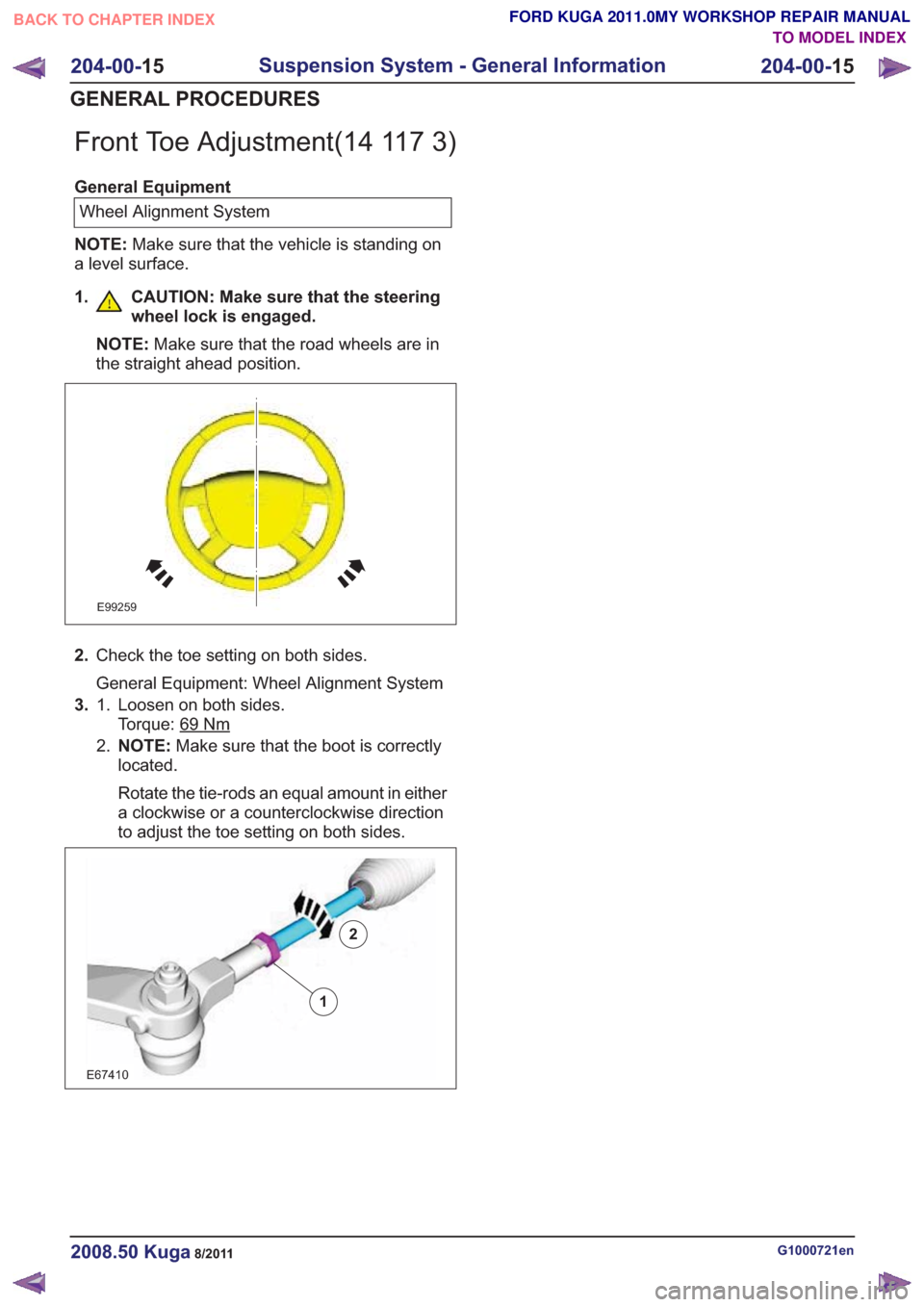
1. CAUTION: Make sure that the steering wheel lock is engaged.
NOTE: Make sure that the road wheels are in
the straight ahead position.
E99259
2. Check the toe setting on both sides.
General Equipment: Wheel Alignment System
3. Loosen on both sides.
Torque: 69
Nm
1.
2.NOTE: Make sure that the boot is correctly
located.
Rotate the tie-rods an equal amount in either
a clockwise or a counterclockwise direction
to adjust the toe setting on both sides.
2
E67410
1
2
G1000721en2008.50 Kuga8/2011
204-00- 15
Suspension System - General Information
204-00- 15
GENERAL PROCEDURES
TO MODEL INDEX
BACK TO CHAPTER INDEX
FORD KUGA 2011.0MY WORKSHOP REPAIR MANUAL
Page 1202 of 2057
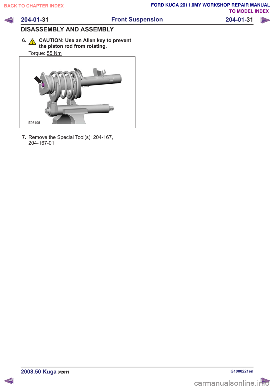
6. CAUTION: Use an Allen key to preventthe piston rod from rotating.
Torque: 55Nm
E98495
7.Remove the Special Tool(s): 204-167,
204-167-01
G1000221en2008.50 Kuga8/2011
204-01- 31
Front Suspension
204-01- 31
DISASSEMBLY AND ASSEMBLY
TO MODEL INDEX
BACK TO CHAPTER INDEX
FORD KUGA 2011.0MY WORKSHOP REPAIR MANUAL
Page 1349 of 2057
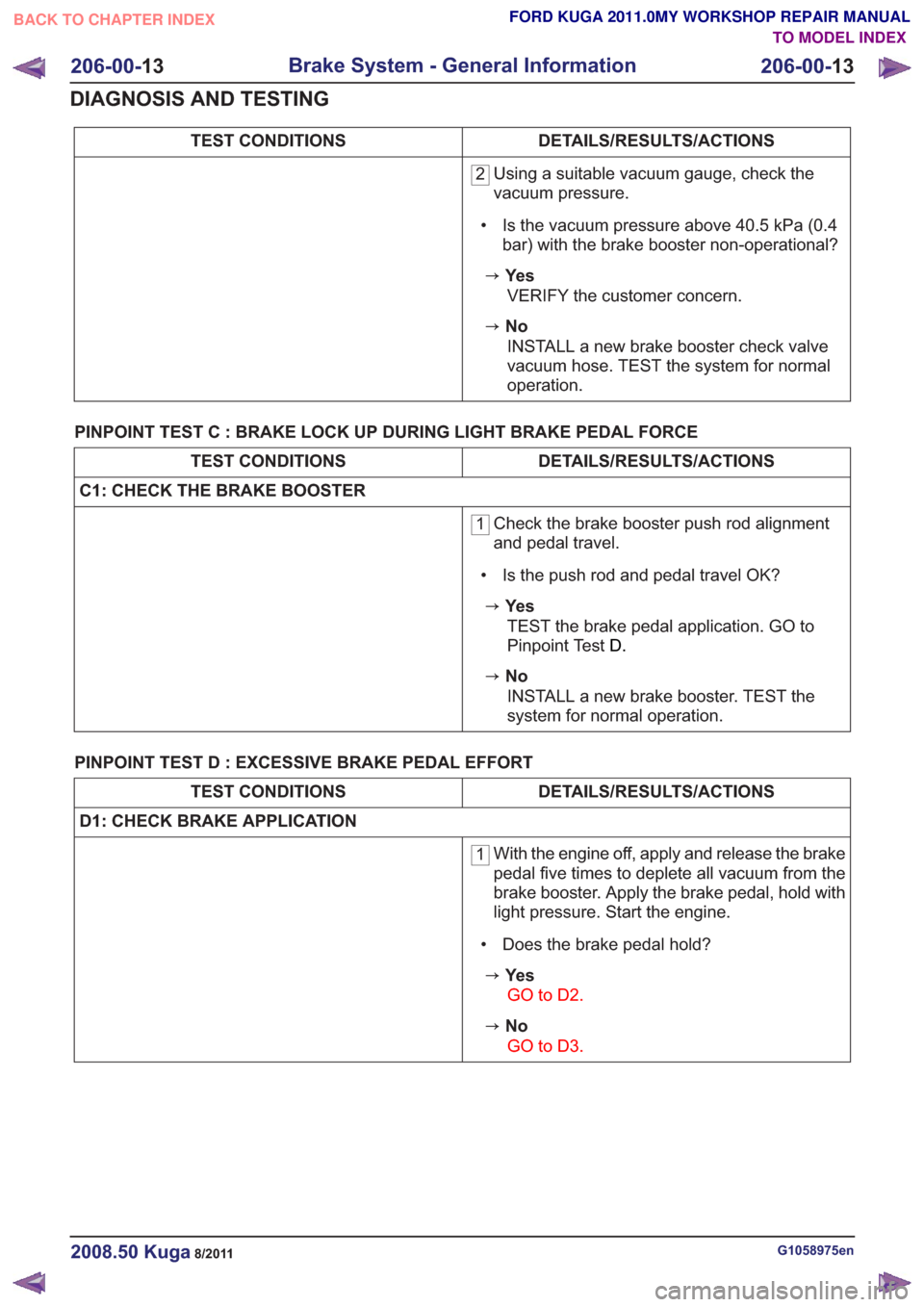
DETAILS/RESULTS/ACTIONS
TEST CONDITIONS
2 Using a suitable vacuum gauge, check the
vacuum pressure.
• Is the vacuum pressure above 40.5 kPa (0.4 bar) with the brake booster non-operational?
zYe s
VERIFY the customer concern.
zNoINSTALL a new brake booster check valve
vacuum hose. TEST the system for normal
operation.
PINPOINT TEST C : BRAKE LOCK UP DURING LIGHT BRAKE PEDAL FORCE
DETAILS/RESULTS/ACTIONS
TEST CONDITIONS
C1: CHECK THE BRAKE BOOSTER
1 Check the brake booster push rod alignment
and pedal travel.
• Is the push rod and pedal travel OK?
zYe s TEST the brake pedal application. GO to
Pinpoint Test D.
zNo
INSTALL a new brake booster. TEST the
system for normal operation.
PINPOINT TEST D : EXCESSIVE BRAKE PEDAL EFFORT
DETAILS/RESULTS/ACTIONS
TEST CONDITIONS
D1: CHECK BRAKE APPLICATION
1 With the engine off, apply and release the brake
pedal five times to deplete all vacuum from the
brake booster. Apply the brake pedal, hold with
light pressure. Start the engine.
• Does the brake pedal hold?
zYe s GO to D2 .
zNo
GO to D3 .
G1058975en2008.50 Kuga8/2011
206-00-13
Brake System - General Information
206-00- 13
DIAGNOSIS AND TESTING
TO MODEL INDEX
BACK TO CHAPTER INDEX
FORD KUGA 2011.0MY WORKSHOP REPAIR MANUAL