2011 FORD KUGA rod
[x] Cancel search: rodPage 1445 of 2057
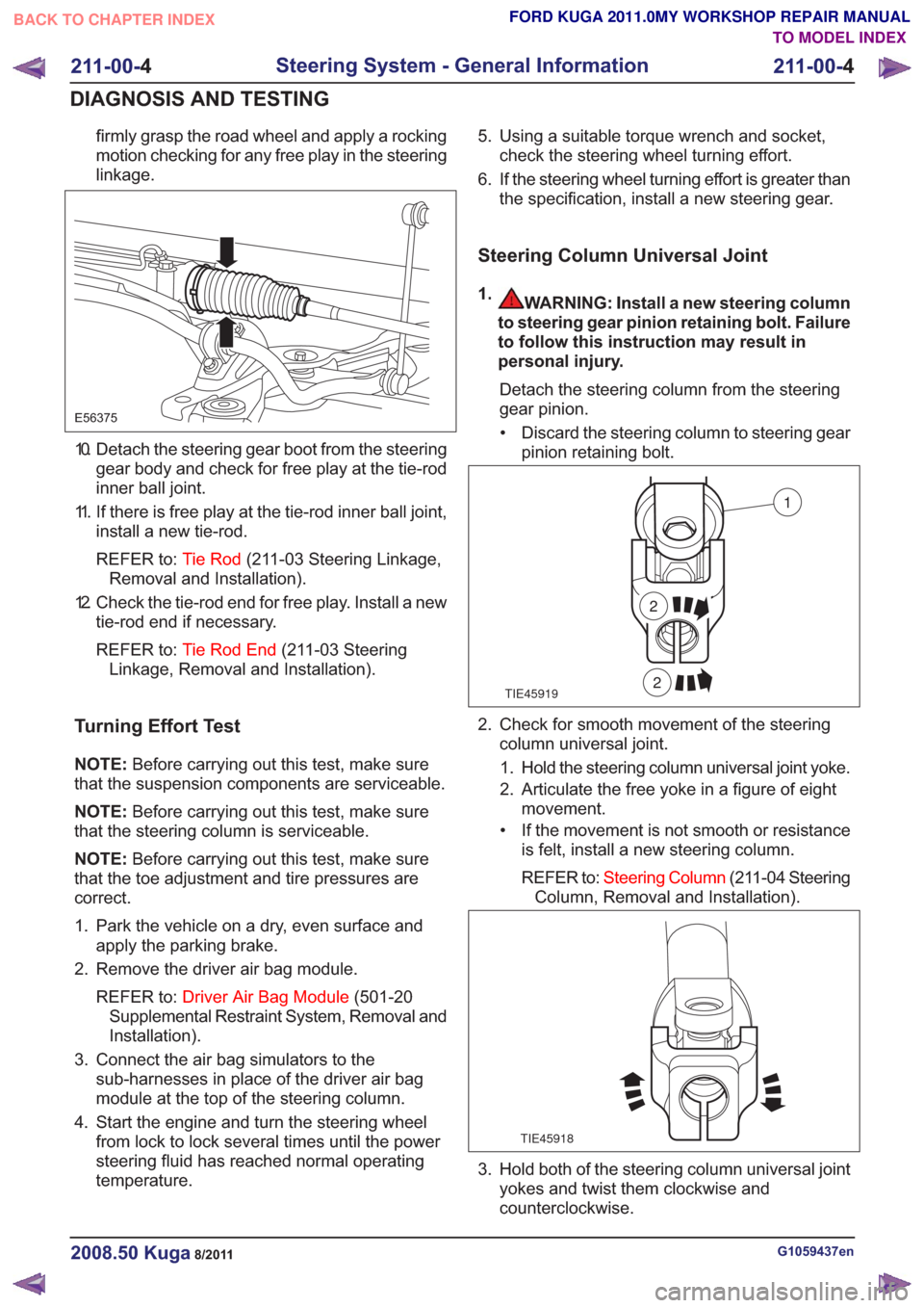
firmly grasp the road wheel and apply a rocking
motion checking for any free play in the steering
linkage.
E56375
10. Detach the steering gear boot from the steeringgear body and check for free play at the tie-rod
inner ball joint.
11. If there is free play at the tie-rod inner ball joint, install a new tie-rod.
REFER to: Tie Rod(211-03 Steering Linkage,
Removal and Installation).
12. Check the tie-rod end for free play. Install a new tie-rod end if necessary.
REFER to: Tie Rod End (211-03 Steering
Linkage, Removal and Installation).
Turning Effort Test
NOTE: Before carrying out this test, make sure
that the suspension components are serviceable.
NOTE: Before carrying out this test, make sure
that the steering column is serviceable.
NOTE: Before carrying out this test, make sure
that the toe adjustment and tire pressures are
correct.
1. Park the vehicle on a dry, even surface and apply the parking brake.
2. Remove the driver air bag module.
REFER to: Driver Air Bag Module (501-20
Supplemental Restraint System, Removal and
Installation).
3. Connect the air bag simulators to the sub-harnesses in place of the driver air bag
module at the top of the steering column.
4. Start the engine and turn the steering wheel from lock to lock several times until the power
steering fluid has reached normal operating
temperature. 5. Using a suitable torque wrench and socket,
check the steering wheel turning effort.
6. If the steering wheel turning effort is greater than the specification, install a new steering gear.
Steering Column Universal Joint
1.WARNING: Install a new steering column
to steering gear pinion retaining bolt. Failure
to follow this instruction may result in
personal injury.
Detach the steering column from the steering
gear pinion.• Discard the steering column to steering gear pinion retaining bolt.
TIE45919
1
2
2
2. Check for smooth movement of the steeringcolumn universal joint.
1. Hold the steering column universal joint yoke.
2. Articulate the free yoke in a figure of eight movement.
• If the movement is not smooth or resistance is felt, install a new steering column.
REFER to: Steering Column (211-04 Steering
Column, Removal and Installation).
TIE45918
3. Hold both of the steering column universal joint yokes and twist them clockwise and
counterclockwise.
G1059437en2008.50 Kuga8/2011
211-00- 4
Steering System - General Information
211-00- 4
DIAGNOSIS AND TESTING
TO MODEL INDEX
BACK TO CHAPTER INDEX
FORD KUGA 2011.0MY WORKSHOP REPAIR MANUAL
Page 1447 of 2057
Steering Gear Checks After a Collision
General EquipmentFeeler gauge
Straight edge
Items to be observed when checking the steering
system
The following list of steering gear conditions and
the methods of testing should be taken into account
when carrying out checks to the steering system:
• If the steering gear has no faults after completing the following checks, do not install
a new steering gear.
• Surface corrosion and marks on the tie-rod are acceptable.
• When checking for turning effort torque peaks in the steering gear, turn the steering wheel from
steering lock stop to steering lock stop in
approximately 15 seconds.
• A steady increase of turning effort torque from steering center to steering lock stop is
acceptable.
• When checking for power steering fluid leaks, turn the steering wheel to the steering lock stop
in approximately 10 seconds.
• Noises from the power steering, for example the power steering pump relief valve, are
acceptable.
STEERING GEAR HOUSING
1. Raise and support the vehicle. REFER to: Lifting(100-02 Jacking and Lifting,
Description and Operation).
2. Visually inspect the steering gear housing for cracks and damage. If the steering gear housing
is cracked or damaged, install a new steering
gear.
REFER to: Steering Gear (211-02 Power
Steering, Removal and Installation).
TIE-RODS
1. Using a straight edge and feeler gauge, check the tie-rods to see if they are straight. If the
distance between the tie-rod and straight edge is greater than 0.5 mm, install a new steering
gear.
REFER to:
Steering Gear (211-02 Power
Steering, Removal and Installation).
2. Check the tightening torque of the tie-rod end to wheel knuckle nut.
REFER to: Tie Rod End (211-03 Steering
Linkage, Removal and Installation).
3. Check the tightening torque of the tie-rod end locking nut.
REFER to: Tie Rod End (211-03 Steering
Linkage, Removal and Installation).
CHECK FOR TURNING EFFORT TORQUE
PEAKS IN THE STEERING GEAR
1. Lower and support the vehicle making sure that the road wheels are just clear of the floor.
2. With the ignition switch in position I, slowly turn the steering wheel from steering lock stop to
steering lock stop. If a turning effort torque peak
or judder is felt while turning the steering wheel,
detach the tie-rods from the wheel knuckles.
3. Slowly turn the steering wheel from steering lock stop to steering lock stop. If a turning effort
torque peak or judder is felt while turning the
steering wheel, install a new steering gear.
REFER to: Steering Gear (211-02 Power
Steering, Removal and Installation).
CHECK FOR POWER STEERING FLUID LEAKS
1. Lower the vehicle.
2. Run the engine at a fast idle and slowly turn the steering wheel to the left-hand steering lock
stop. Hold the steering wheel in this position for
5 seconds with a turning effort torque of 15 Nm
at the steering wheel rim.
3. Turn the steering wheel away from the left-hand steering lock stop for 30 seconds.
4. Run the engine at a fast idle and slowly turn the steering wheel to the right-hand steering lock
stop. Hold the steering wheel in this position for
5 seconds with a turning effort torque of 15 Nm
at the steering wheel rim.
5. Turn the steering wheel away from the right-hand steering lock stop.
6. Check for power steering fluid leaks at the steering gear housing and the power steering
line connections to the steering gear. If there is
G538091en2008.50 Kuga8/2011
211-00- 6
Steering System - General Information
211-00- 6
DIAGNOSIS AND TESTING
TO MODEL INDEX
BACK TO CHAPTER INDEX
FORD KUGA 2011.0MY WORKSHOP REPAIR MANUAL
Page 1461 of 2057
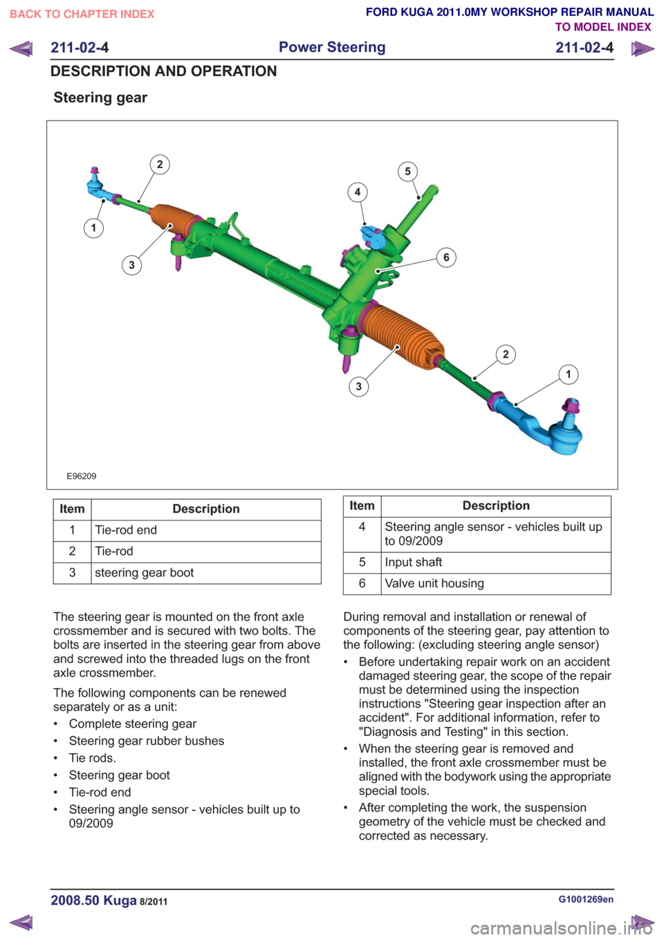
Steering gear
E96209
1
2
3
4
5
1
2
63
Description
Item
Tie-rod end
1
Tie-rod
2
steering gear boot
3Description
Item
Steering angle sensor - vehicles built up
to 09/2009
4
Input shaft
5
Valve unit housing
6
The steering gear is mounted on the front axle
crossmember and is secured with two bolts. The
bolts are inserted in the steering gear from above
and screwed into the threaded lugs on the front
axle crossmember.
The following components can be renewed
separately or as a unit:
• Complete steering gear
• Steering gear rubber bushes
• Tie rods.
• Steering gear boot
• Tie-rod end
• Steering angle sensor - vehicles built up to 09/2009 During removal and installation or renewal of
components of the steering gear, pay attention to
the following: (excluding steering angle sensor)
• Before undertaking repair work on an accident
damaged steering gear, the scope of the repair
must be determined using the inspection
instructions "Steering gear inspection after an
accident". For additional information, refer to
"Diagnosis and Testing" in this section.
• When the steering gear is removed and installed, the front axle crossmember must be
aligned with the bodywork using the appropriate
special tools.
• After completing the work, the suspension geometry of the vehicle must be checked and
corrected as necessary.
G1001269en2008.50 Kuga8/2011
211-02- 4
Power Steering
211-02- 4
DESCRIPTION AND OPERATION
TO MODEL INDEX
BACK TO CHAPTER INDEX
FORD KUGA 2011.0MY WORKSHOP REPAIR MANUAL
Page 1497 of 2057
SECTION 211-03 Steering Linkage
VEHICLE APPLICATION:2008.50 Kuga
PA G E
CONTENTS
REMOVAL AND INSTALLATION
211-03-2
(13 273 0)
Tie Rod End ........................................................................\
............................
211-03-3
(13 263 0)
Tie Rod ........................................................................\
...................................
211-03-5
(13 134 0)
Steering Gear Boot ........................................................................\
.................
211-03-1
Steering Linkage
211-03- 1
.
TO MODEL INDEX
BACK TO CHAPTER INDEX
FORD KUGA 2011.0MY WORKSHOP REPAIR MANUAL
Page 1498 of 2057
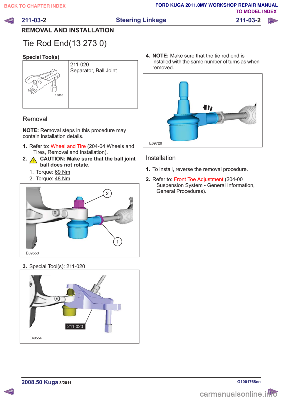
Tie Rod End(13 273 0)
Special Tool(s)211-020
Separator, Ball Joint
13006
Removal
NOTE:Removal steps in this procedure may
contain installation details.
1. Refer to: Wheel and Tire (204-04 Wheels and
Tires, Removal and Installation).
2. CAUTION: Make sure that the ball joint ball does not rotate.
1. Torque: 69Nm
2. Torque: 48Nm
E69553
2
1
3.Special Tool(s): 211-020
E69554
211-020
4. NOTE: Make sure that the tie rod end is
installed with the same number of turns as when
removed.
E69728
Installation
1. To install, reverse the removal procedure.
2. Refer to: Front Toe Adjustment (204-00
Suspension System - General Information,
General Procedures).
G1001768en2008.50 Kuga8/2011
211-03- 2
Steering Linkage
211-03- 2
REMOVAL AND INSTALLATION
TO MODEL INDEX
BACK TO CHAPTER INDEX
FORD KUGA 2011.0MY WORKSHOP REPAIR MANUAL
Page 1499 of 2057
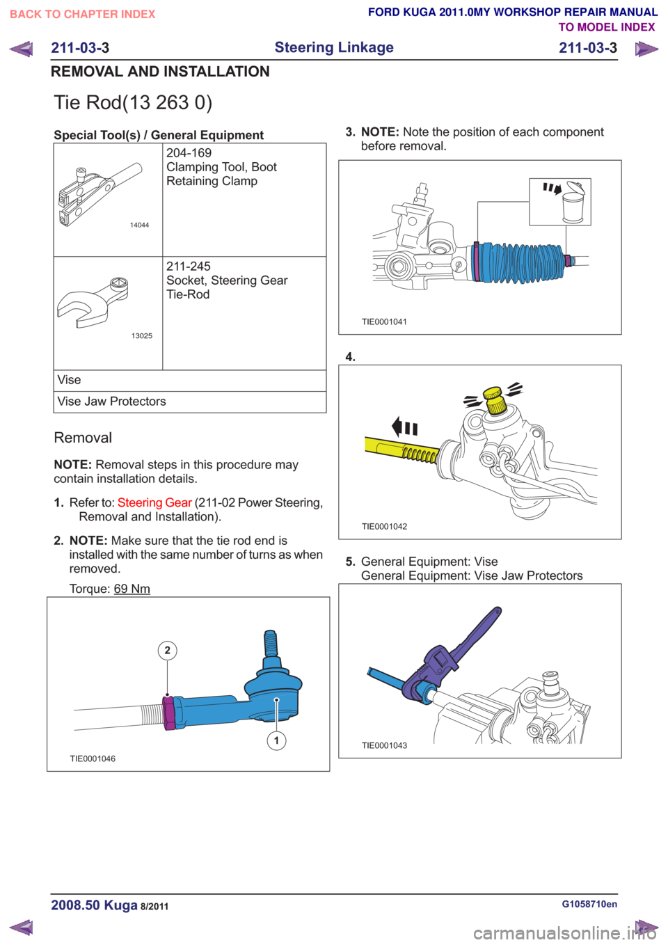
Tie Rod(13 263 0)
Special Tool(s) / General Equipment204-169
Clamping Tool, Boot
Retaining Clamp
14044
211-245
Socket, Steering Gear
Tie-Rod
13025
Vise
Vise Jaw Protectors
Removal
NOTE:Removal steps in this procedure may
contain installation details.
1. Refer to: Steering Gear (211-02 Power Steering,
Removal and Installation).
2. NOTE: Make sure that the tie rod end is
installed with the same number of turns as when
removed.
Torque: 69
Nm
TIE0001046
1
2
3. NOTE: Note the position of each component
before removal.
TIE0001041
4.
TIE0001042
5. General Equipment: Vise
General Equipment: Vise Jaw Protectors
TIE0001043
G1058710en2008.50 Kuga8/2011
211-03- 3
Steering Linkage
211-03- 3
REMOVAL AND INSTALLATION
TO MODEL INDEX
BACK TO CHAPTER INDEX
FORD KUGA 2011.0MY WORKSHOP REPAIR MANUAL
Page 1501 of 2057
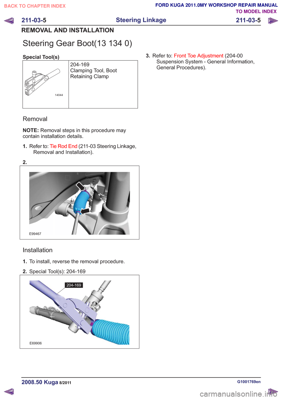
Steering Gear Boot(13 134 0)
Special Tool(s)204-169
Clamping Tool, Boot
Retaining Clamp
14044
Removal
NOTE:Removal steps in this procedure may
contain installation details.
1. Refer to: Tie Rod End (211-03 Steering Linkage,
Removal and Installation).
2.
E99467
Installation
1. To install, reverse the removal procedure.
2. Special Tool(s): 204-169
E69906
204-169
3.Refer to: Front Toe Adjustment (204-00
Suspension System - General Information,
General Procedures).
G1001769en2008.50 Kuga8/2011
211-03- 5
Steering Linkage
211-03- 5
REMOVAL AND INSTALLATION
TO MODEL INDEX
BACK TO CHAPTER INDEX
FORD KUGA 2011.0MY WORKSHOP REPAIR MANUAL
Page 1518 of 2057
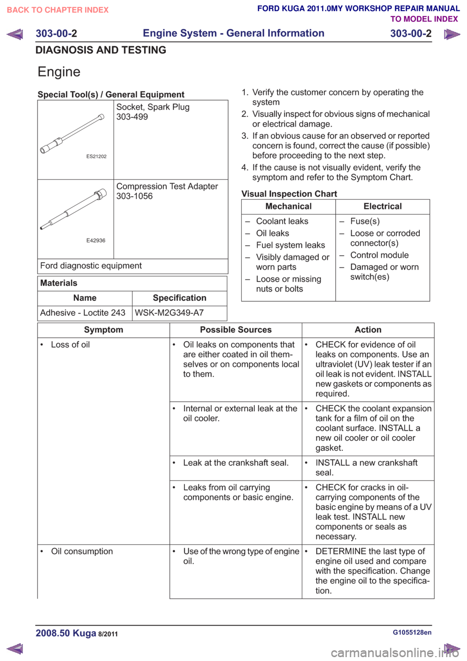
Engine
Special Tool(s) / General EquipmentSocket, Spark Plug
303-499
ES21202
Compression Test Adapter
303-1056
E42936
Ford diagnostic equipment
Materials
Specification
Name
WSK-M2G349-A7
Adhesive - Loctite 243 1. Verify the customer concern by operating the
system
2. Visually inspect for obvious signs of mechanical or electrical damage.
3. If an obvious cause for an observed or reported concern is found, correct the cause (if possible)
before proceeding to the next step.
4. If the cause is not visually evident, verify the symptom and refer to the Symptom Chart.
Visual Inspection Chart
Electrical
Mechanical
– Fuse(s)
– Loose or corrodedconnector(s)
– Control module
– Damaged or worn switch(es)
– Coolant leaks
– Oil leaks
– Fuel system leaks
– Visibly damaged or
worn parts
– Loose or missing nuts or bolts
Action
Possible Sources
Symptom
• CHECK for evidence of oilleaks on components. Use an
ultraviolet (UV) leak tester if an
oil leak is not evident. INSTALL
new gaskets or components as
required.
• Oil leaks on components that
are either coated in oil them-
selves or on components local
to them.
• Loss of oil
• CHECK the coolant expansiontank for a film of oil on the
coolant surface. INSTALL a
new oil cooler or oil cooler
gasket.
• Internal or external leak at the
oil cooler.
• INSTALL a new crankshaftseal.
• Leak at the crankshaft seal.
• CHECK for cracks in oil-carrying components of the
basic engine by means of a UV
leak test. INSTALL new
components or seals as
necessary.
• Leaks from oil carrying
components or basic engine.
• DETERMINE the last type ofengine oil used and compare
with the specification. Change
the engine oil to the specifica-
tion.
• Use of the wrong type of engine
oil.
• Oil consumption
G1055128en2008.50 Kuga8/2011
303-00-
2
Engine System - General Information
303-00- 2
DIAGNOSIS AND TESTING
TO MODEL INDEX
BACK TO CHAPTER INDEX
FORD KUGA 2011.0MY WORKSHOP REPAIR MANUAL