Page 1656 of 2057
14.
E112635
2
1
15.Torque: 10Nm1.
2. General Equipment: Hose Clamp
Remover/Installer
4. Torque: 30
Nm
E112636
4
2
x3
3
x31
x3
3
1x3
G1191241en2008.50 Kuga8/2011
303-01- 123
Engine— 2.5L Duratec (147kW/200PS) - VI5303-01-
123
INSTALLATION
TO MODEL INDEX
BACK TO CHAPTER INDEX
FORD KUGA 2011.0MY WORKSHOP REPAIR MANUAL
Page 1660 of 2057
31.General Equipment: Hose Clamp
Remover/Installer
E68473
E66479
33. Torque: 48Nm1.
2. Torque: 25
Nm
3. Torque: 10Nm
x41
3
2
E114615
G1191241en2008.50 Kuga8/2011
303-01- 127
Engine— 2.5L Duratec (147kW/200PS) - VI5303-01-
127
INSTALLATION
FORD KUGA 2011.0MY WORKSHOP REPAIR MANUAL
TO MODEL INDEX
BACK TO CHAPTER INDEX
32.
Page 1663 of 2057
E112637
2
1
1
42.General Equipment: Hose Clamp
Remover/Installer
G1191241en2008.50 Kuga8/2011
303-01- 130
Engine— 2.5L Duratec (147kW/200PS) - VI5303-01-
130
INSTALLATION
TO MODEL INDEX
BACK TO CHAPTER INDEX
FORD KUGA 2011.0MY WORKSHOP REPAIR MANUAL
Page 1668 of 2057
Vehicles with PCM security shield
53.Torque: 7Nm
x4x4
E92343
All vehicles
54. CAUTION: Make sure that no
components catch.
Remove the following items:
• General Equipment: Retaining Strap
55. N O T E : Only tighten the bolts finger tight at this
stage. Remove the following items:
• General Equipment: Trolley Jack
E116626
56. CAUTION: Make sure that the inside of the pipe ends are clean and free of oil
residue.
1. Torque: 4Nm
2. Torque: 10Nm
E116646
1
2
2
G1191241en2008.50 Kuga8/2011
303-01- 135
Engine— 2.5L Duratec (147kW/200PS) - VI5303-01-
135
INSTALLATION
TO MODEL INDEX
BACK TO CHAPTER INDEX
FORD KUGA 2011.0MY WORKSHOP REPAIR MANUAL
Page 1669 of 2057
57.
E65070
58.
E106249
59.
E112389
60.
E112311
61.To r q u e : 115Nm1.
2. Torque: 90
Nm
E68740
1
2
62.General Equipment: Hose Clamp
Remover/Installer
E112638
G1191241en2008.50 Kuga8/2011
303-01- 136
Engine— 2.5L Duratec (147kW/200PS) - VI5303-01-
136
INSTALLATION
TO MODEL INDEX
BACK TO CHAPTER INDEX
FORD KUGA 2011.0MY WORKSHOP REPAIR MANUAL
Page 1677 of 2057

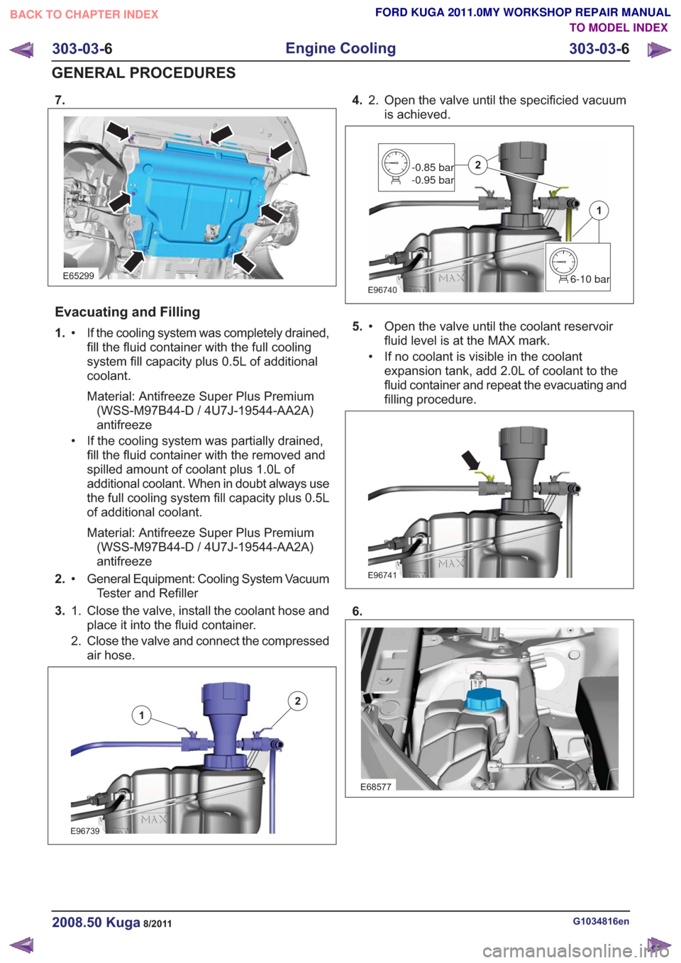
7.
E65299
Evacuating and Filling
1.If the cooling system was completely drained,
fill the fluid container with the full cooling
•
system fill capacity plus 0.5L of additional
coolant.
Material: Antifreeze Super Plus Premium(WSS-M97B44-D / 4U7J-19544-AA2A)
antifreeze
• If the cooling system was partially drained, fill the fluid container with the removed and
spilled amount of coolant plus 1.0L of
additional coolant. When in doubt always use
the full cooling system fill capacity plus 0.5L
of additional coolant.
Material: Antifreeze Super Plus Premium(WSS-M97B44-D / 4U7J-19544-AA2A)
antifreeze
2. General Equipment: Cooling System Vacuum
Tester and Refiller
•
3. Close the valve, install the coolant hose and
place it into the fluid container.
1.
2. Close the valve and connect the compressed
air hose.
E96739
1
2
4. Open the valve until the specificied vacuum
is achieved.
2.
E967406-10 bar
1
-0.85 bar
-0.95 bar2
5.
Open the valve until the coolant reservoir
fluid level is at the MAX mark.
•
• If no coolant is visible in the coolant
expansion tank, add 2.0L of coolant to the
fluid container and repeat the evacuating and
filling procedure.
E96741
6.
E68577
G1034816en2008.50 Kuga8/2011
303-03- 6
Engine Cooling
303-03- 6
GENERAL PROCEDURES
TO MODEL INDEX
BACK TO CHAPTER INDEX
FORD KUGA 2011.0MY WORKSHOP REPAIR MANUAL
Page 1680 of 2057
8.Torque: 25Nm
E100040
x4
9.
E98184
10.
E98183
11 .Remove the cable ties securing the radiator and
condenser assembly.
G1062292en2008.50 Kuga8/2011
303-03- 9
Engine Cooling
303-03- 9
GENERAL PROCEDURES
TO MODEL INDEX
BACK TO CHAPTER INDEX
FORD KUGA 2011.0MY WORKSHOP REPAIR MANUAL
Page 1681 of 2057

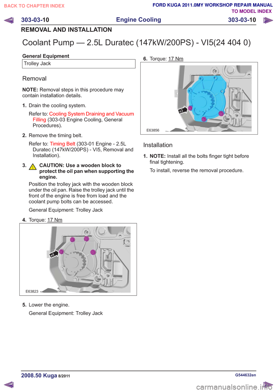
Coolant Pump — 2.5L Duratec (147kW/200PS) - VI5(24 404 0)
General EquipmentTrolley Jack
Removal
NOTE: Removal steps in this procedure may
contain installation details.
1. Drain the cooling system.
Refer to: Cooling System Draining and Vacuum
Filling (303-03 Engine Cooling, General
Procedures).
2. Remove the timing belt.
Refer to: Timing Belt (303-01 Engine - 2.5L
Duratec (147kW/200PS) - VI5, Removal and
Installation).
3. CAUTION: Use a wooden block to protect the oil pan when supporting the
engine.
Position the trolley jack with the wooden block
under the oil pan. Raise the trolley jack until the
front of the engine is free from load and the
coolant pump bolts can be accessed.
General Equipment: Trolley Jack
4. Torque: 17
Nm
E63823
x4
5.Lower the engine.
General Equipment: Trolley Jack 6.
Torque: 17
Nm
x3
E63856
Installation
1. NOTE: Install all the bolts finger tight before
final tightening.
To install, reverse the removal procedure.
G544632en2008.50 Kuga8/2011
303-03- 10
Engine Cooling
303-03- 10
REMOVAL AND INSTALLATION
TO MODEL INDEX
BACK TO CHAPTER INDEX
FORD KUGA 2011.0MY WORKSHOP REPAIR MANUAL