2011 FORD KUGA cv joint
[x] Cancel search: cv jointPage 1319 of 2057
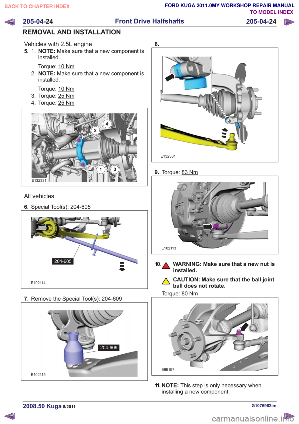
Vehicles with 2.5L engine
5. NOTE:Make sure that a new component is
installed.
Torque: 10
Nm
1.
2. NOTE: Make sure that a new component is
installed.
Torque: 10
Nm
3. Torque: 25Nm
4. Torque: 25Nm
2
4
13
2
4
13
E132331
All vehicles
6. Special Tool(s): 204-605
E102114
204-605
7.Remove the Special Tool(s): 204-609
E102115
204-609
8.
E132381
9.Torque: 83Nm
E102113
10. WARNING: Make sure that a new nut is
installed.
CAUTION: Make sure that the ball joint
ball does not rotate.
Torque: 80
Nm
E99197
11. NOTE: This step is only necessary when
installing a new component.
G1076962en2008.50 Kuga8/2011
205-04- 24
Front Drive Halfshafts
205-04- 24
REMOVAL AND INSTALLATION
TO MODEL INDEX
BACK TO CHAPTER INDEX
FORD KUGA 2011.0MY WORKSHOP REPAIR MANUAL
Page 1322 of 2057
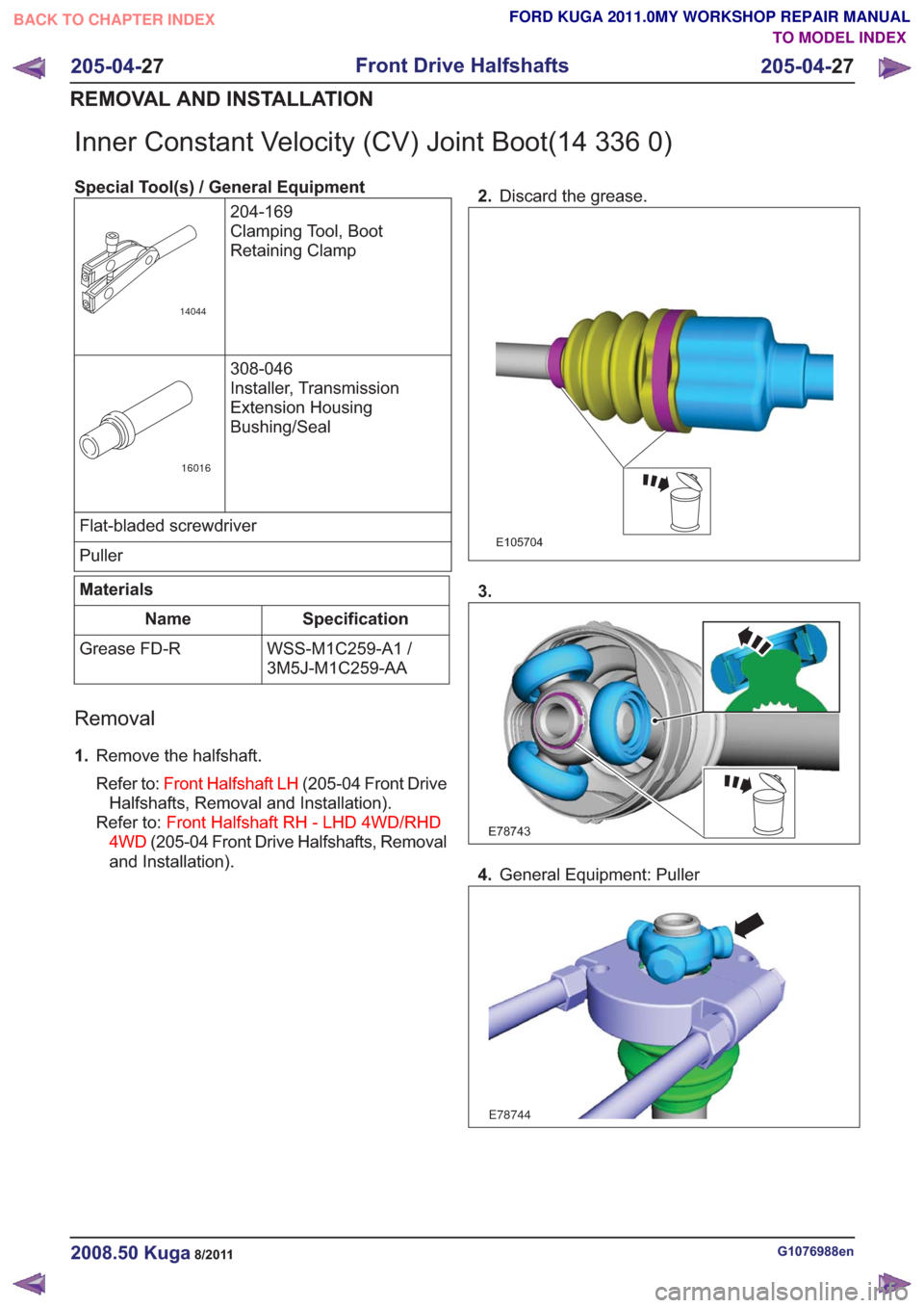
Inner Constant Velocity (CV) Joint Boot(14 336 0)
Special Tool(s) / General Equipment204-169
Clamping Tool, Boot
Retaining Clamp
14044
308-046
Installer, Transmission
Extension Housing
Bushing/Seal
16016
Flat-bladed screwdriver
Puller
Materials
Specification
Name
WSS-M1C259-A1 /
3M5J-M1C259-AA
Grease FD-R
Removal
1.
Remove the halfshaft.
Refer to: Front Halfshaft LH (205-04 Front Drive
Halfshafts, Removal and Installation).
Refer to: Front Halfshaft RH - LHD 4WD/RHD
4WD (205-04 Front Drive Halfshafts, Removal
and Installation). 2.
Discard the grease.
E105704
3.
E78743
4.General Equipment: Puller
E78744
G1076988en2008.50 Kuga8/2011
205-04- 27
Front Drive Halfshafts
205-04- 27
REMOVAL AND INSTALLATION
TO MODEL INDEX
BACK TO CHAPTER INDEX
FORD KUGA 2011.0MY WORKSHOP REPAIR MANUAL
Page 1325 of 2057
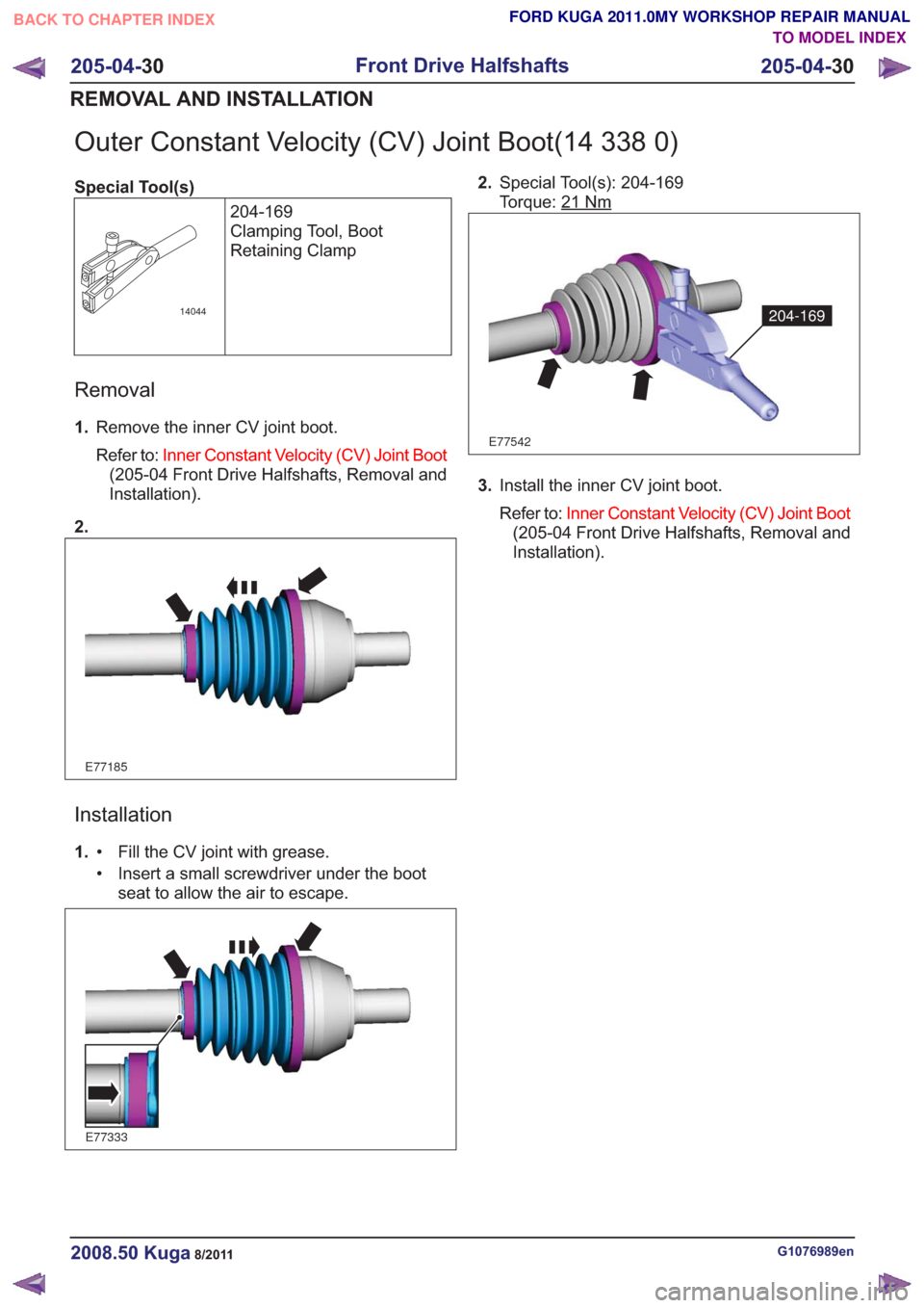
Outer Constant Velocity (CV) Joint Boot(14 338 0)
Special Tool(s)204-169
Clamping Tool, Boot
Retaining Clamp
14044
Removal
1.Remove the inner CV joint boot.
Refer to: Inner Constant Velocity (CV) Joint Boot
(205-04 Front Drive Halfshafts, Removal and
Installation).
2.
E77185
Installation
1. Fill the CV joint with grease.
•
• Insert a small screwdriver under the boot
seat to allow the air to escape.
E77333
2.Special Tool(s): 204-169
Torque: 21
Nm
E77542
204-169
3.Install the inner CV joint boot.
Refer to: Inner Constant Velocity (CV) Joint Boot
(205-04 Front Drive Halfshafts, Removal and
Installation).
G1076989en2008.50 Kuga8/2011
205-04- 30
Front Drive Halfshafts
205-04- 30
REMOVAL AND INSTALLATION
TO MODEL INDEX
BACK TO CHAPTER INDEX
FORD KUGA 2011.0MY WORKSHOP REPAIR MANUAL
Page 1443 of 2057
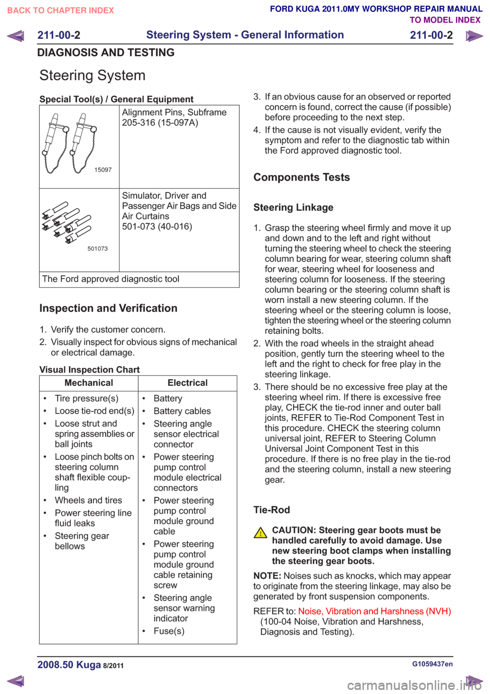
Steering System
Special Tool(s) / General EquipmentAlignment Pins, Subframe
205-316 (15-097A)
15097
Simulator, Driver and
Passenger Air Bags and Side
Air Curtains
501-073 (40-016)
501073
The Ford approved diagnostic tool
Inspection and Verification
1. Verify the customer concern.
2. Visually inspect for obvious signs of mechanicalor electrical damage.
Visual Inspection Chart
Electrical
Mechanical
• Battery
• Battery cables
• Steering anglesensor electrical
connector
• Power steering pump control
module electrical
connectors
• Power steering pump control
module ground
cable
• Power steering pump control
module ground
cable retaining
screw
• Steering angle sensor warning
indicator
• Fuse(s)
• Tire pressure(s)
• Loose tie-rod end(s)
• Loose strut and
spring assemblies or
ball joints
• Loose pinch bolts on steering column
shaft flexible coup-
ling
• Wheels and tires
• Power steering line fluid leaks
• Steering gear bellows 3. If an obvious cause for an observed or reported
concern is found, correct the cause (if possible)
before proceeding to the next step.
4. If the cause is not visually evident, verify the symptom and refer to the diagnostic tab within
the Ford approved diagnostic tool.
Components Tests
Steering Linkage
1. Grasp the steering wheel firmly and move it upand down and to the left and right without
turning the steering wheel to check the steering
column bearing for wear, steering column shaft
for wear, steering wheel for looseness and
steering column for looseness. If the steering
column bearing or the steering column shaft is
worn install a new steering column. If the
steering wheel or the steering column is loose,
tighten the steering wheel or the steering column
retaining bolts.
2. With the road wheels in the straight ahead position, gently turn the steering wheel to the
left and the right to check for free play in the
steering linkage.
3. There should be no excessive free play at the steering wheel rim. If there is excessive free
play, CHECK the tie-rod inner and outer ball
joints, REFER to Tie-Rod Component Test in
this procedure. CHECK the steering column
universal joint, REFER to Steering Column
Universal Joint Component Test in this
procedure. If there is no free play in the tie-rod
and the steering column, install a new steering
gear.
Tie-Rod
CAUTION: Steering gear boots must be
handled carefully to avoid damage. Use
new steering boot clamps when installing
the steering gear boots.
NOTE: Noises such as knocks, which may appear
to originate from the steering linkage, may also be
generated by front suspension components.
REFER to: Noise, Vibration and Harshness (NVH)
(100-04 Noise, Vibration and Harshness,
Diagnosis and Testing).
G1059437en2008.50 Kuga8/2011
211-00- 2
Steering System - General Information
211-00- 2
DIAGNOSIS AND TESTING
TO MODEL INDEX
BACK TO CHAPTER INDEX
FORD KUGA 2011.0MY WORKSHOP REPAIR MANUAL
Page 1444 of 2057
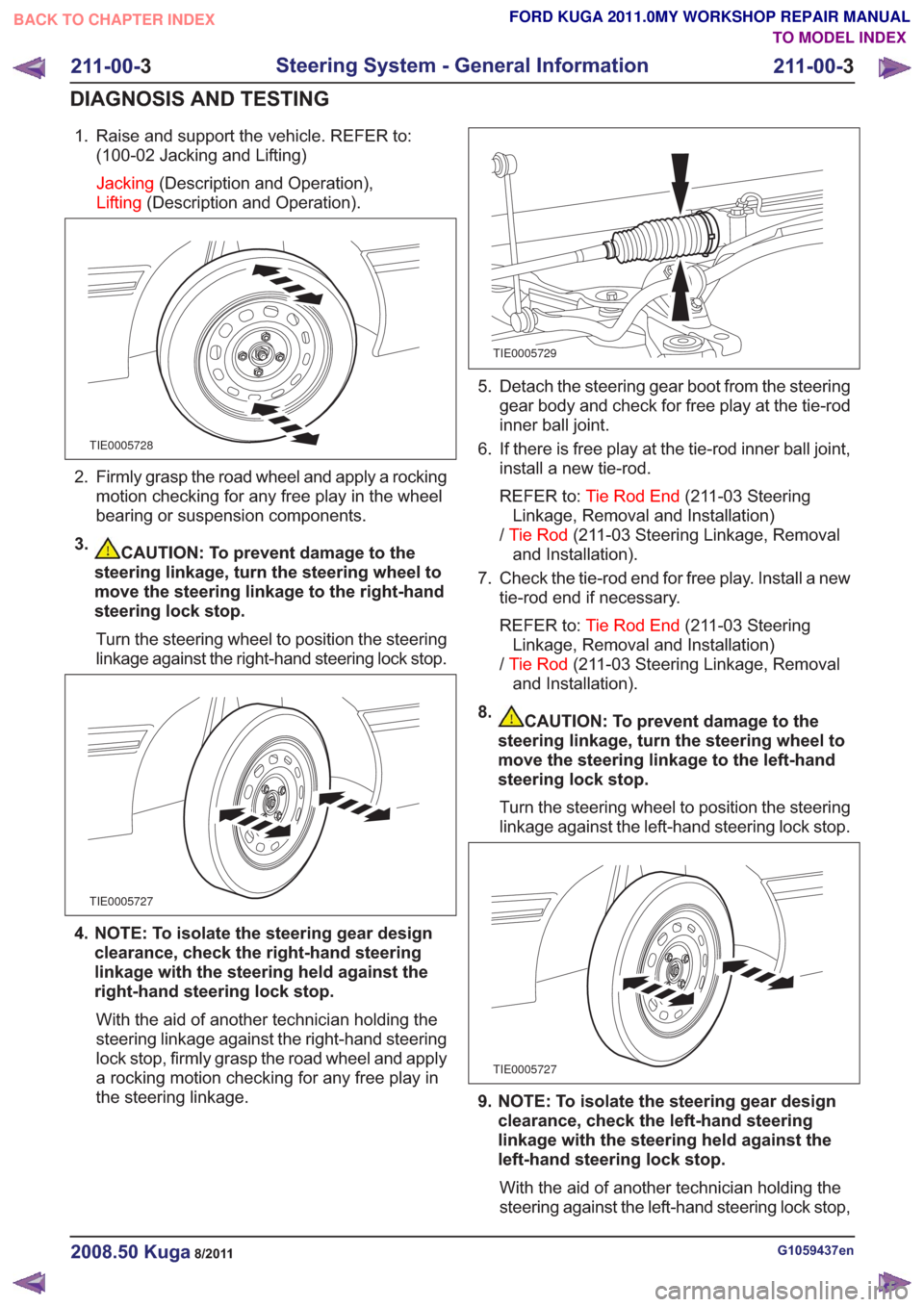
1. Raise and support the vehicle. REFER to:(100-02 Jacking and Lifting)
Jacking (Description and Operation),
Lifting (Description and Operation).
TIE0005728
2. Firmly grasp the road wheel and apply a rocking
motion checking for any free play in the wheel
bearing or suspension components.
3.
CAUTION: To prevent damage to the
steering linkage, turn the steering wheel to
move the steering linkage to the right-hand
steering lock stop.
Turn the steering wheel to position the steering
linkage against the right-hand steering lock stop.
TIE0005727
4. NOTE: To isolate the steering gear design clearance, check the right-hand steering
linkage with the steering held against the
right-hand steering lock stop.
With the aid of another technician holding the
steering linkage against the right-hand steering
lock stop, firmly grasp the road wheel and apply
a rocking motion checking for any free play in
the steering linkage.
TIE0005729
5. Detach the steering gear boot from the steering gear body and check for free play at the tie-rod
inner ball joint.
6. If there is free play at the tie-rod inner ball joint, install a new tie-rod.
REFER to: Tie Rod End (211-03 Steering
Linkage, Removal and Installation)
/ Tie Rod (211-03 Steering Linkage, Removal
and Installation).
7. Check the tie-rod end for free play. Install a new tie-rod end if necessary.
REFER to: Tie Rod End (211-03 Steering
Linkage, Removal and Installation)
/ Tie Rod (211-03 Steering Linkage, Removal
and Installation).
8.
CAUTION: To prevent damage to the
steering linkage, turn the steering wheel to
move the steering linkage to the left-hand
steering lock stop.
Turn the steering wheel to position the steering
linkage against the left-hand steering lock stop.
TIE0005727
9. NOTE: To isolate the steering gear design clearance, check the left-hand steering
linkage with the steering held against the
left-hand steering lock stop.
With the aid of another technician holding the
steering against the left-hand steering lock stop,
G1059437en2008.50 Kuga8/2011
211-00- 3
Steering System - General Information
211-00- 3
DIAGNOSIS AND TESTING
TO MODEL INDEX
BACK TO CHAPTER INDEX
FORD KUGA 2011.0MY WORKSHOP REPAIR MANUAL
Page 1445 of 2057
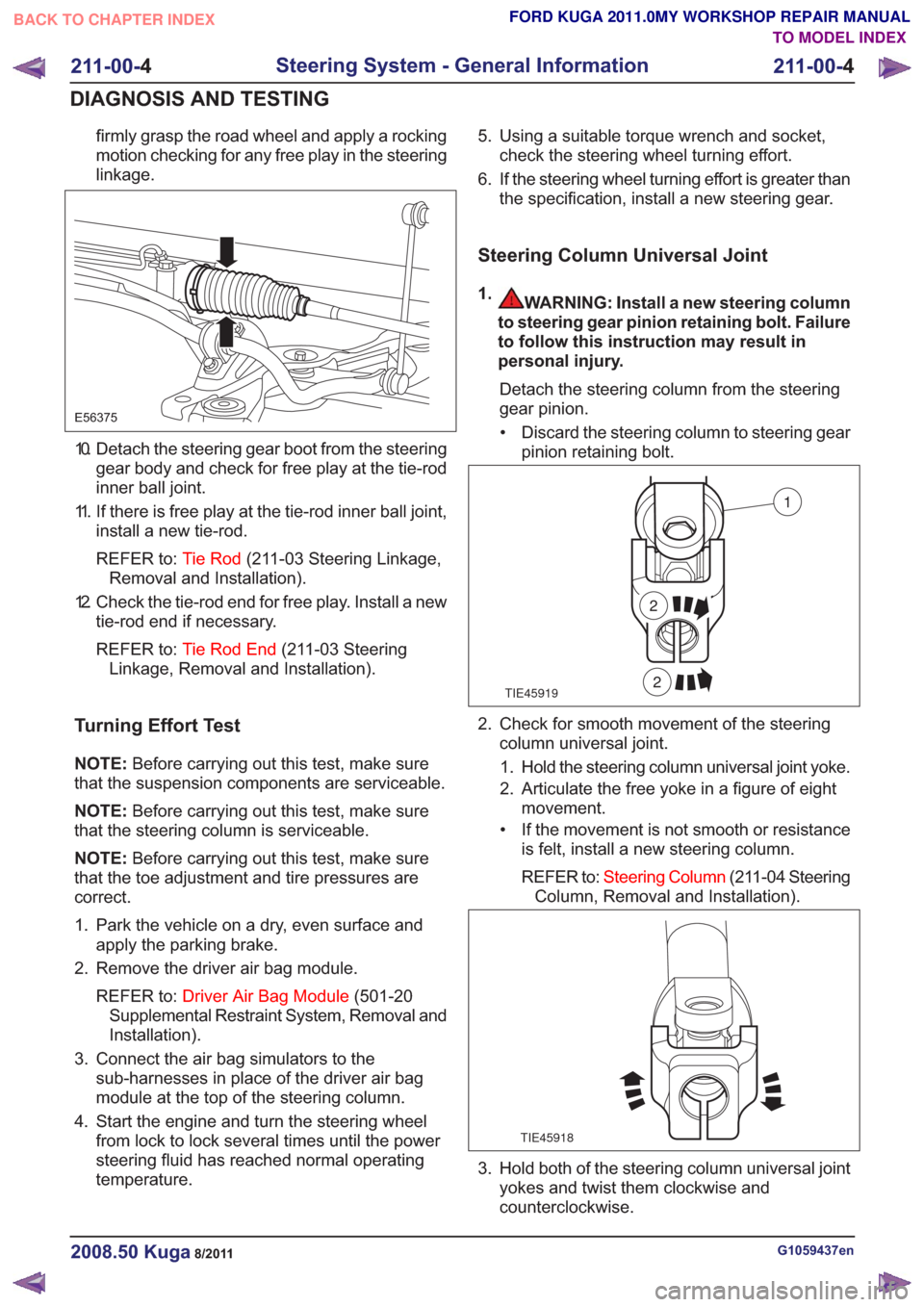
firmly grasp the road wheel and apply a rocking
motion checking for any free play in the steering
linkage.
E56375
10. Detach the steering gear boot from the steeringgear body and check for free play at the tie-rod
inner ball joint.
11. If there is free play at the tie-rod inner ball joint, install a new tie-rod.
REFER to: Tie Rod(211-03 Steering Linkage,
Removal and Installation).
12. Check the tie-rod end for free play. Install a new tie-rod end if necessary.
REFER to: Tie Rod End (211-03 Steering
Linkage, Removal and Installation).
Turning Effort Test
NOTE: Before carrying out this test, make sure
that the suspension components are serviceable.
NOTE: Before carrying out this test, make sure
that the steering column is serviceable.
NOTE: Before carrying out this test, make sure
that the toe adjustment and tire pressures are
correct.
1. Park the vehicle on a dry, even surface and apply the parking brake.
2. Remove the driver air bag module.
REFER to: Driver Air Bag Module (501-20
Supplemental Restraint System, Removal and
Installation).
3. Connect the air bag simulators to the sub-harnesses in place of the driver air bag
module at the top of the steering column.
4. Start the engine and turn the steering wheel from lock to lock several times until the power
steering fluid has reached normal operating
temperature. 5. Using a suitable torque wrench and socket,
check the steering wheel turning effort.
6. If the steering wheel turning effort is greater than the specification, install a new steering gear.
Steering Column Universal Joint
1.WARNING: Install a new steering column
to steering gear pinion retaining bolt. Failure
to follow this instruction may result in
personal injury.
Detach the steering column from the steering
gear pinion.• Discard the steering column to steering gear pinion retaining bolt.
TIE45919
1
2
2
2. Check for smooth movement of the steeringcolumn universal joint.
1. Hold the steering column universal joint yoke.
2. Articulate the free yoke in a figure of eight movement.
• If the movement is not smooth or resistance is felt, install a new steering column.
REFER to: Steering Column (211-04 Steering
Column, Removal and Installation).
TIE45918
3. Hold both of the steering column universal joint yokes and twist them clockwise and
counterclockwise.
G1059437en2008.50 Kuga8/2011
211-00- 4
Steering System - General Information
211-00- 4
DIAGNOSIS AND TESTING
TO MODEL INDEX
BACK TO CHAPTER INDEX
FORD KUGA 2011.0MY WORKSHOP REPAIR MANUAL
Page 1482 of 2057
Steering Gear(13 116 0)
Special Tool(s) / General Equipment205-880
Alignment Pins, Subframe
E93105
211-020
Separator, Ball Joint
13006
Transmission Jack
Materials
Specification
Name
WSA-M2C195-A / 9U7J-
M2C195-AA
Power Steering Fluid IW
Removal
NOTE:
Removal steps in this procedure may
contain installation details.
1. Refer to: Steering System Health and Safety
Precautions (100-00 General Information,
Description and Operation).
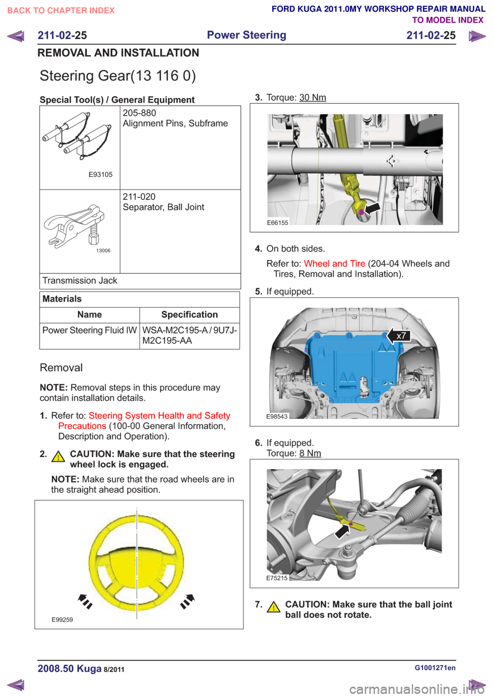
2. CAUTION: Make sure that the steering wheel lock is engaged.
NOTE: Make sure that the road wheels are in
the straight ahead position.
E99259
3. Torque: 30Nm
E66155
4.On both sides.
Refer to: Wheel and Tire (204-04 Wheels and
Tires, Removal and Installation).
5. If equipped.
E98543
x7
6.If equipped.
Torque: 8
Nm
E75215
7. CAUTION: Make sure that the ball joint
ball does not rotate.
G1001271en2008.50 Kuga8/2011
211-02- 25
Power Steering
211-02- 25
REMOVAL AND INSTALLATION
TO MODEL INDEX
BACK TO CHAPTER INDEX
FORD KUGA 2011.0MY WORKSHOP REPAIR MANUAL
Page 1498 of 2057
Tie Rod End(13 273 0)
Special Tool(s)211-020
Separator, Ball Joint
13006
Removal
NOTE:Removal steps in this procedure may
contain installation details.
1. Refer to: Wheel and Tire (204-04 Wheels and
Tires, Removal and Installation).
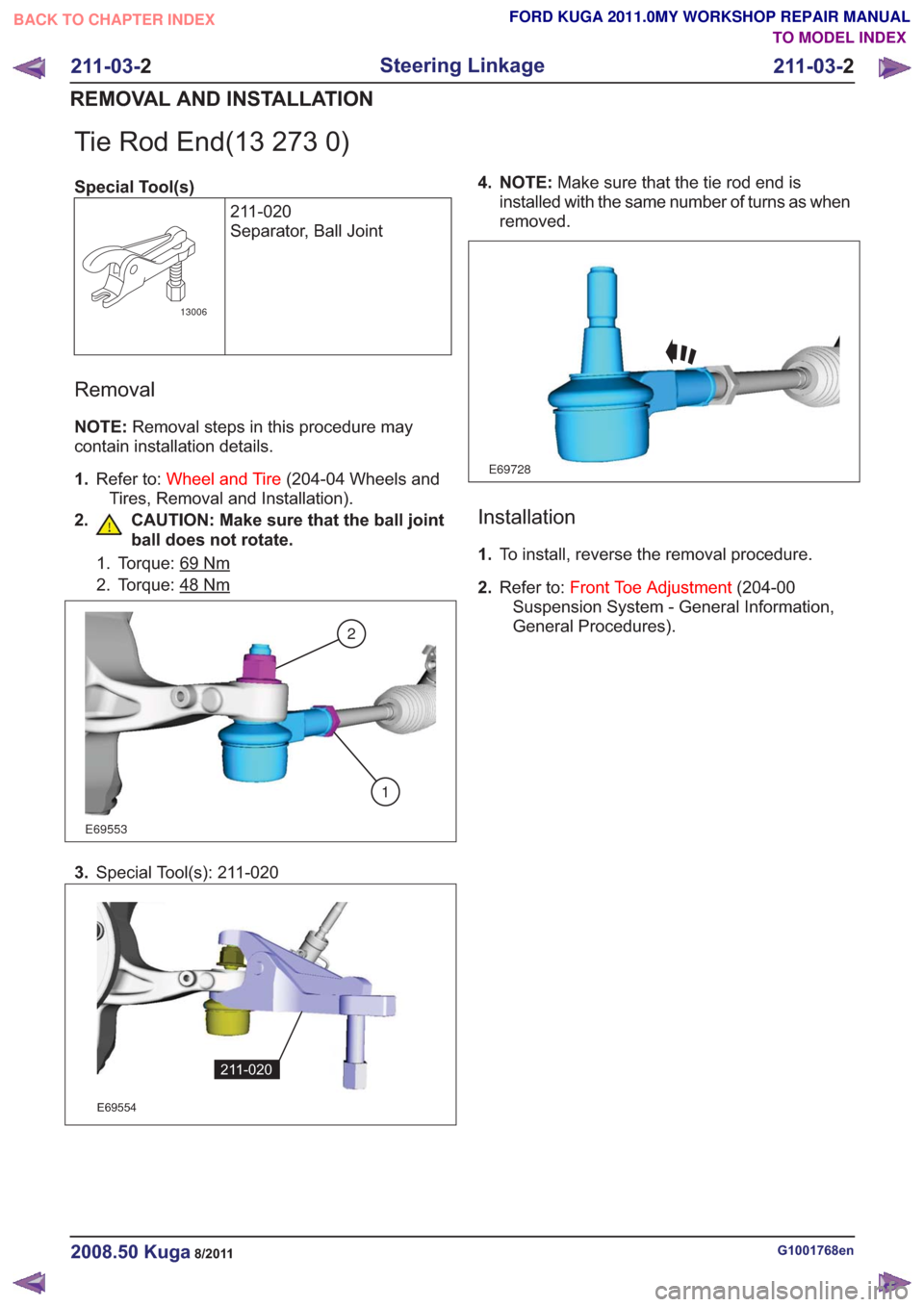
2. CAUTION: Make sure that the ball joint ball does not rotate.
1. Torque: 69Nm
2. Torque: 48Nm
E69553
2
1
3.Special Tool(s): 211-020
E69554
211-020
4. NOTE: Make sure that the tie rod end is
installed with the same number of turns as when
removed.
E69728
Installation
1. To install, reverse the removal procedure.
2. Refer to: Front Toe Adjustment (204-00
Suspension System - General Information,
General Procedures).
G1001768en2008.50 Kuga8/2011
211-03- 2
Steering Linkage
211-03- 2
REMOVAL AND INSTALLATION
TO MODEL INDEX
BACK TO CHAPTER INDEX
FORD KUGA 2011.0MY WORKSHOP REPAIR MANUAL