Page 369 of 2057
Trailer Module
Removal
1.
Refer to: Loadspace Trim Panel LH (501-05
Interior Trim and Ornamentation, Removal
and Installation).
2. Installation
1.
To install, reverse the removal procedure. G1158252en
2008.50 Kuga 8/2011 417-01-35
Exterior Lighting
417-01-35
REMOVAL AND INSTALLATIONTO MODEL INDEX
BACK TO CHAPTER INDEX
FORD KUGA 2011.0MY WORKSHOP REPAIR MANUALE122607
Page 374 of 2057
Interior Lighting
Refer to
Wiring Diagrams Section 417-02, for
schematic and connector information. General Equipment
The Ford approved diagnostic tool
Inspection and Verification
1. Verify the customer concern.
2. Visually inspect for obvious signs of electrical damage.
Visual Inspection Chart Electrical
– Fuse(s)
– Bulb(s)
– Switch(es)
– Wiring harness
– Electrical connector(s)
– Interior lamp(s)
– Battery saver relay
– Door
– Central junction box (CJB)
3. If an obvious cause for an observed or reported concern is found, correct the cause (if possible)
before proceeding to the next step.
4. If the cause is not visually evident, verify the symptom and refer to the diagnostic tab within
the Ford approved diagnostic tool. G1055016en
2008.50 Kuga 8/2011 417-02-2
Interior Lighting
417-02-2
DIAGNOSIS AND TESTINGTO MODEL INDEX
BACK TO CHAPTER INDEX
FORD KUGA 2011.0MY WORKSHOP REPAIR MANUAL
Page 402 of 2057

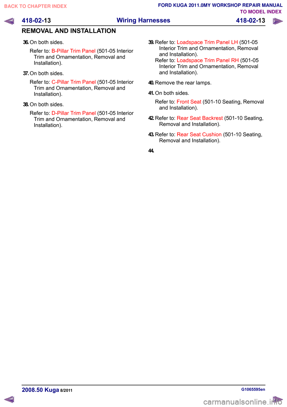
36.
On both sides.
Refer to: B-Pillar Trim Panel (501-05 Interior
Trim and Ornamentation, Removal and
Installation).
37. On both sides.
Refer to: C-Pillar Trim Panel (501-05 Interior
Trim and Ornamentation, Removal and
Installation).
38. On both sides.
Refer to: D-Pillar Trim Panel (501-05 Interior
Trim and Ornamentation, Removal and
Installation). 39.
Refer to: Loadspace Trim Panel LH (501-05
Interior Trim and Ornamentation, Removal
and Installation).
Refer to: Loadspace Trim Panel RH (501-05
Interior Trim and Ornamentation, Removal
and Installation).
40. Remove the rear lamps.
41. On both sides.
Refer to: Front Seat (501-10 Seating, Removal
and Installation).
42. Refer to: Rear Seat Backrest (501-10 Seating,
Removal and Installation).
43. Refer to: Rear Seat Cushion (501-10 Seating,
Removal and Installation).
44. G1065595en
2008.50 Kuga 8/2011 418-02-13
Wiring Harnesses
418-02-13
REMOVAL AND INSTALLATIONTO MODEL INDEX
BACK TO CHAPTER INDEX
FORD KUGA 2011.0MY WORKSHOP REPAIR MANUAL
Page 426 of 2057
Engine Compartment Wiring Harness
Removal
NOTE:
Removal steps in this procedure may
contain installation details.
1. 2.
Refer to: Headlamp Assembly (417-01 Exterior
Lighting, Removal and Installation).
3. Refer to: Wheel and Tire (204-04 Wheels and
Tires, Removal and Installation).
4. Refer to: Fender Splash Shield (501-02 Front
End Body Panels, Removal and Installation).
5. Refer to: Front Bumper Cover (501-19 Bumpers,
Removal and Installation).
6. Torque: 10 Nm
7.
Torque: 10 Nm
G1065599en
2008.50 Kuga 8/2011 418-02-37
Wiring Harnesses
418-02-37
REMOVAL AND INSTALLATIONTO MODEL INDEX
BACK TO CHAPTER INDEX
FORD KUGA 2011.0MY WORKSHOP REPAIR MANUALE102365
Page 443 of 2057
Anti-Theft Alarm Horn with Integral Battery
Removal
1.
Refer to: Cowl Panel Grille (501-02 Front End
Body Panels, Removal and Installation).
2. 3.
Installation
1.
To install, reverse the removal procedure. G1065602en
2008.50 Kuga 8/2011 419-01A-11
Anti-Theft - Active
419-01A-11
REMOVAL AND INSTALLATIONTO MODEL INDEX
BACK TO CHAPTER INDEX
FORD KUGA 2011.0MY WORKSHOP REPAIR MANUALE114592 E114593
Page 460 of 2057
Windshield wash/wipe system
Refer to:
Wipers and Washers (501-16 Wipers and
Washers, Description and Operation).
Anti-theft
Refer to: Anti-Theft - Active (419-01 Anti-Theft -
Active, Description and Operation).
Electric booster Heater
Refer to: Auxiliary Climate Control (412-02 Auxiliary
Climate Control, Description and Operation).
Climate control
Refer to: Climate Control (412-01 Climate Control,
Description and Operation). G1030788en
2008.50 Kuga 8/2011 419-10-10
Multifunction Electronic Modules
419-10-10
DESCRIPTION AND OPERATIONTO MODEL INDEX
BACK TO CHAPTER INDEX
FORD KUGA 2011.0MY WORKSHOP REPAIR MANUAL
Page 1197 of 2057
Front Strut and Spring Assembly(14 781 0; 14 782 0)
Special Tool(s)204-159
Lever, Wheel Knuckle
14039
204-605
Separator, Lower Arm Ball
Joint
E63772
Removal
NOTE:Removal steps in this procedure may
contain installation details.
1. Refer to: Cowl Panel Grille (501-02 Front End
Body Panels, Removal and Installation).
2.
E101070
G1000210en2008.50 Kuga8/2011
204-01- 26
Front Suspension
204-01- 26
REMOVAL AND INSTALLATION
TO MODEL INDEX
BACK TO CHAPTER INDEX
FORD KUGA 2011.0MY WORKSHOP REPAIR MANUAL
Page 1299 of 2057

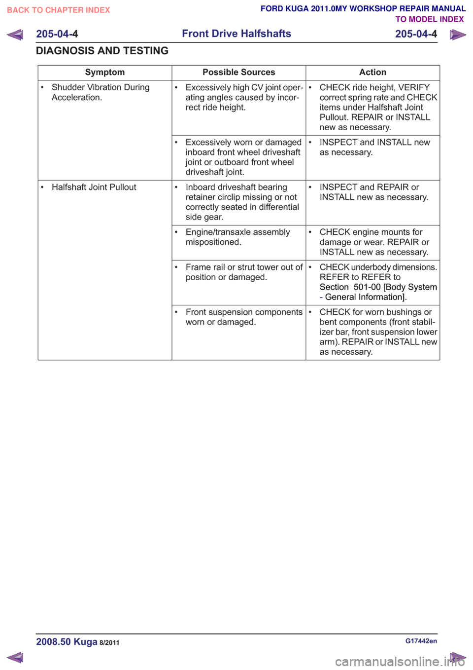
Action
Possible Sources
Symptom
• CHECK ride height, VERIFYcorrect spring rate and CHECK
items under Halfshaft Joint
Pullout. REPAIR or INSTALL
new as necessary.
• Excessively high CV joint oper-
ating angles caused by incor-
rect ride height.
• Shudder Vibration During
Acceleration.
• INSPECT and INSTALL newas necessary.
• Excessively worn or damaged
inboard front wheel driveshaft
joint or outboard front wheel
driveshaft joint.
• INSPECT and REPAIR orINSTALL new as necessary.
• Inboard driveshaft bearing
retainer circlip missing or not
correctly seated in differential
side gear.
• Halfshaft Joint Pullout
• CHECK engine mounts fordamage or wear. REPAIR or
INSTALL new as necessary.
• Engine/transaxle assembly
mispositioned.
• CHECK underbody dimensions.REFER to REFER to
Section 501-00 [Body System
-General Information] .
• Frame rail or strut tower out of
position or damaged.
• CHECK for worn bushings orbent components (front stabil-
izer bar, front suspension lower
arm). REPAIR or INSTALL new
as necessary.
• Front suspension components
worn or damaged.
G17442en2008.50 Kuga8/2011
205-04- 4
Front Drive Halfshafts
205-04- 4
DIAGNOSIS AND TESTING
TO MODEL INDEX
BACK TO CHAPTER INDEX
FORD KUGA 2011.0MY WORKSHOP REPAIR MANUAL