Page 1508 of 2057

Steering Column Shaft
Removal
WARNINGS:
The supplemental restraint system (SRS)
is active for a certain length of time after
the power supply has been disconnected.
Wait for a minimum of 3 minutes before
disconnecting or removing any SRS
components.
Make sure that the vehicle electrical
system is fully depowered and no other
power source is connected.
NOTE: Removal steps in this procedure may
contain installation details.
1. Refer to: Clockspring (501-20 Supplemental
Restraint System, Removal and Installation).
Refer to: Steering Column Multifunction Switch
LH (211-05 Steering Column Switches,
Removal and Installation).
Refer to: Steering Column Multifunction Switch
RH (211-05 Steering Column Switches,
Removal and Installation).
Refer to: Steering Column Lock Module (211-05
Steering Column Switches, Removal and
Installation).
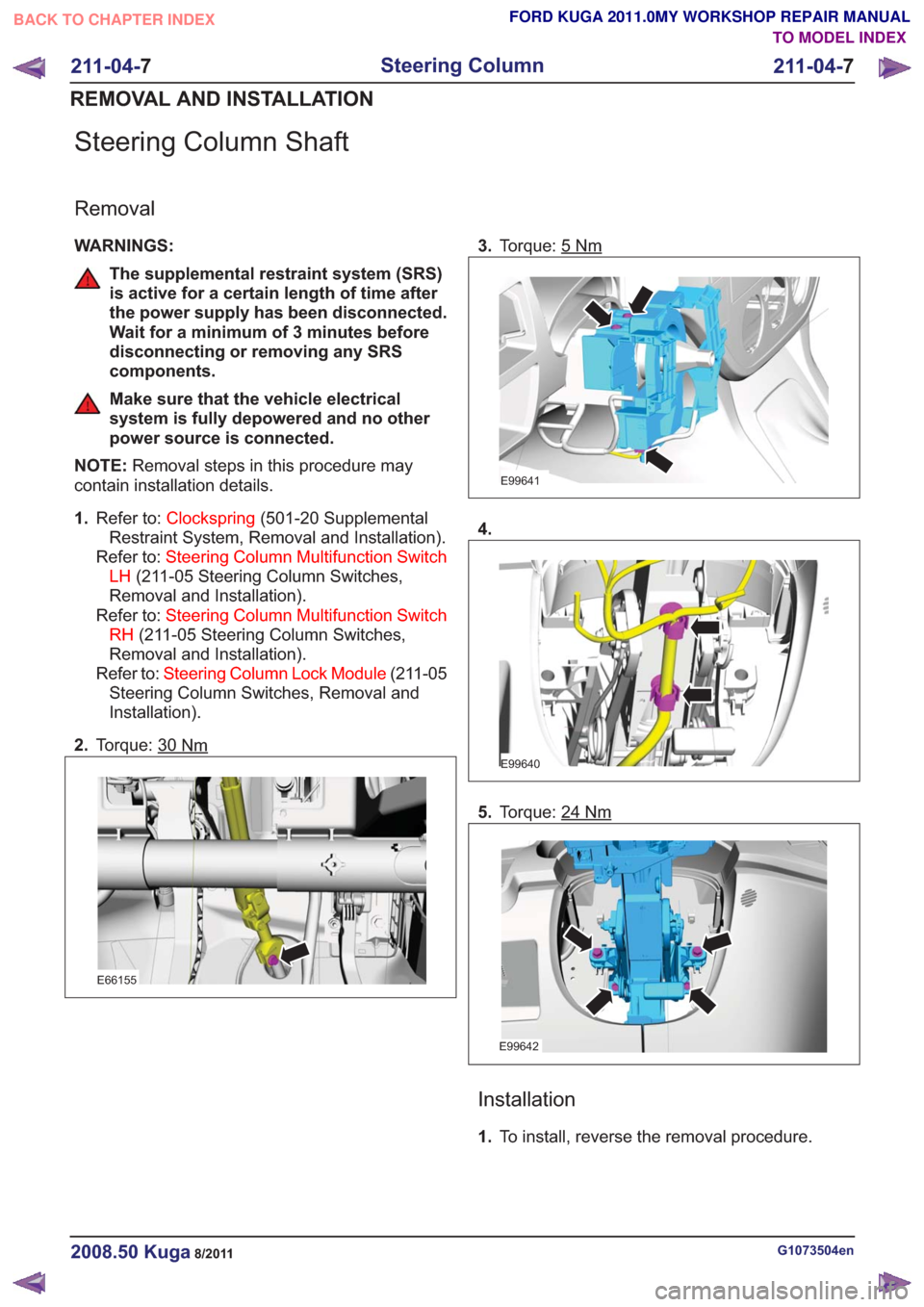
2. Torque: 30
Nm
E66155
3.Torque: 5Nm
E99641
4.
E99640
5.Torque: 24Nm
E99642
Installation
1.To install, reverse the removal procedure.
G1073504en2008.50 Kuga8/2011
211-04- 7
Steering Column
211-04- 7
REMOVAL AND INSTALLATION
TO MODEL INDEX
BACK TO CHAPTER INDEX
FORD KUGA 2011.0MY WORKSHOP REPAIR MANUAL
Page 1512 of 2057
Steering Column Lock Module
General EquipmentFord approved diagnostic tool
Removal
NOTE: Removal steps in this procedure may
contain installation details.
1.
E99717
1
2
3
2. Refer to: Floor Console (501-12 Instrument
Panel and Console, Removal and Installation).
3.
E99718
4.
E99719
5.
E99720
6.
E99721
x2
Installation
1. To install, reverse the removal procedure.
G1058706en2008.50 Kuga8/2011
211-05- 4
Steering Column Switches
211-05- 4
REMOVAL AND INSTALLATION
TO MODEL INDEX
BACK TO CHAPTER INDEX
FORD KUGA 2011.0MY WORKSHOP REPAIR MANUAL
Page 1528 of 2057

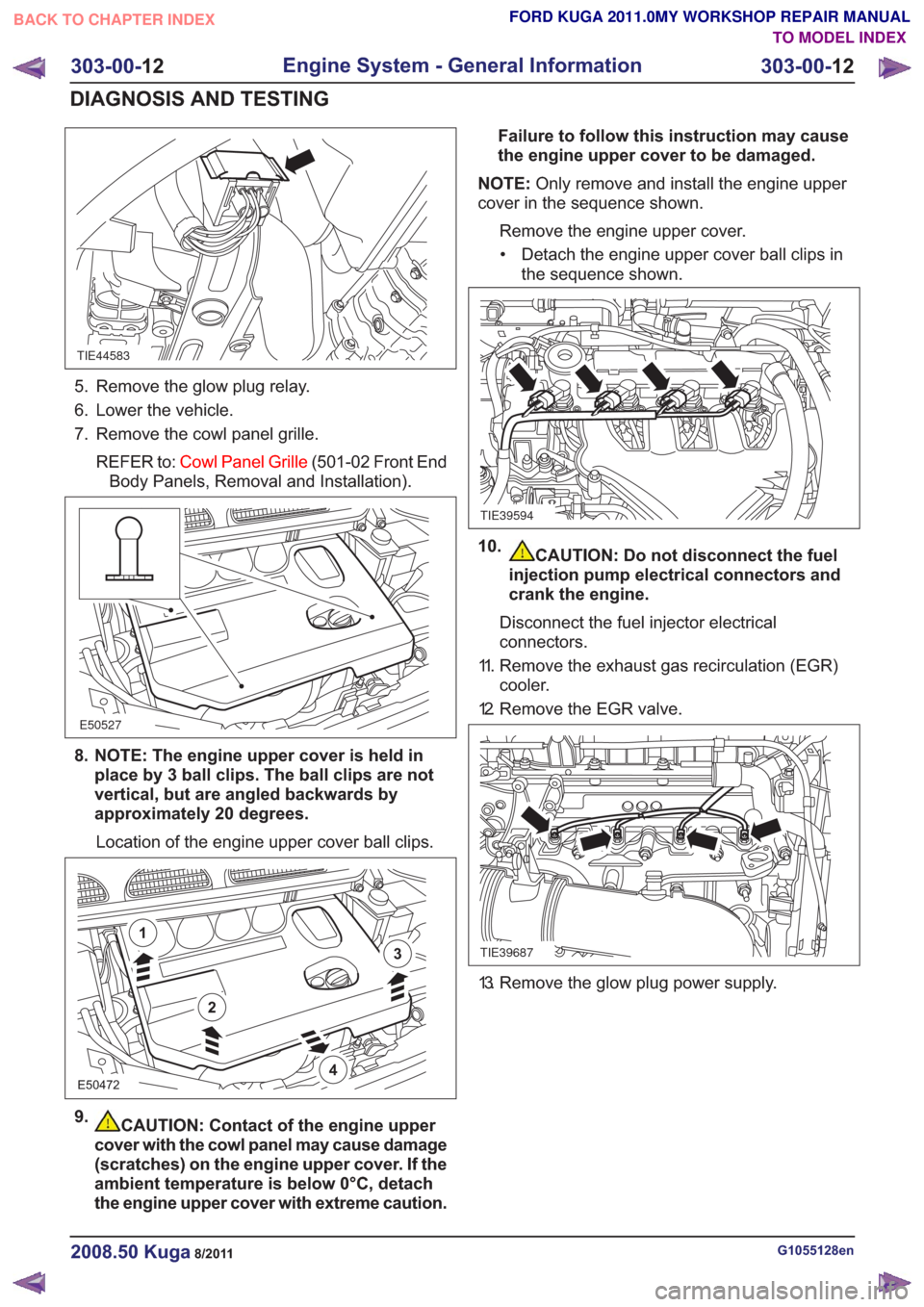
TIE44583
5. Remove the glow plug relay.
6. Lower the vehicle.
7. Remove the cowl panel grille.REFER to: Cowl Panel Grille (501-02 Front End
Body Panels, Removal and Installation).
E50527
8. NOTE: The engine upper cover is held in place by 3 ball clips. The ball clips are not
vertical, but are angled backwards by
approximately 20 degrees.
Location of the engine upper cover ball clips.
E50472
2
1
3
4
9.CAUTION: Contact of the engine upper
cover with the cowl panel may cause damage
(scratches) on the engine upper cover. If the
ambient temperature is below 0°C, detach
the engine upper cover with extreme caution. Failure to follow this instruction may cause
the engine upper cover to be damaged.
NOTE: Only remove and install the engine upper
cover in the sequence shown.
Remove the engine upper cover.• Detach the engine upper cover ball clips in the sequence shown.
TIE39594
10.CAUTION: Do not disconnect the fuel
injection pump electrical connectors and
crank the engine.
Disconnect the fuel injector electrical
connectors.
11. Remove the exhaust gas recirculation (EGR) cooler.
12. Remove the EGR valve.
TIE39687
13. Remove the glow plug power supply.
G1055128en2008.50 Kuga8/2011
303-00- 12
Engine System - General Information
303-00- 12
DIAGNOSIS AND TESTING
TO MODEL INDEX
BACK TO CHAPTER INDEX
FORD KUGA 2011.0MY WORKSHOP REPAIR MANUAL
Page 1530 of 2057

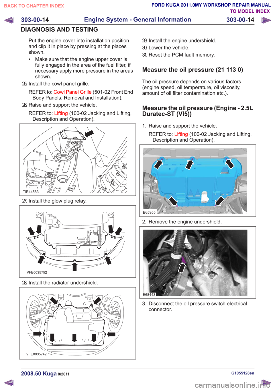
Put the engine cover into installation position
and clip it in place by pressing at the places
shown.• Make sure that the engine upper cover is fully engaged in the area of the fuel filter, if
necessary apply more pressure in the areas
shown.
25. Install the cowl panel grille.
REFER to: Cowl Panel Grille (501-02 Front End
Body Panels, Removal and Installation).
26. Raise and support the vehicle.
REFER to: Lifting(100-02 Jacking and Lifting,
Description and Operation).
TIE44583
27. Install the glow plug relay.
VFE0035752
28. Install the radiator undershield.
VFE0035742
29. Install the engine undershield.
30. Lower the vehicle.
31. Reset the PCM fault memory.
Measure the oil pressure (21 113 0)
The oil pressure depends on various factors
(engine speed, oil temperature, oil viscosity,
amount of oil filter contamination etc.).
Measure the oil pressure (Engine - 2.5L
Duratec-ST (VI5))
1. Raise and support the vehicle.
REFER to: Lifting(100-02 Jacking and Lifting,
Description and Operation).
E65955
2. Remove the engine undershield.
E68443
3. Disconnect the oil pressure switch electrical connector.
G1055128en2008.50 Kuga8/2011
303-00- 14
Engine System - General Information
303-00- 14
DIAGNOSIS AND TESTING
TO MODEL INDEX
BACK TO CHAPTER INDEX
FORD KUGA 2011.0MY WORKSHOP REPAIR MANUAL
Page 1554 of 2057
9.
E67742
10.
E67743
11 .
E67907
12.Torque: 10Nm
E67906
13.
E64165
14.Torque: 19Nm
Installation
1.To install, reverse the removal procedure.
2. Refer to: Door Window Motor Initialization
(501-11 Glass, Frames and Mechanisms,
General Procedures).
G1079020en2008.50 Kuga8/2011
303-01- 21
Engine— 2.5L Duratec (147kW/200PS) - VI5303-01-
21
REMOVAL AND INSTALLATION
TO MODEL INDEX
BACK TO CHAPTER INDEX
FORD KUGA 2011.0MY WORKSHOP REPAIR MANUAL
E67382
Page 1588 of 2057
2. CAUTION: Make sure that fluid level isto the MAX mark.
Refer to: Specifications (303-01 Engine - 2.5L
Duratec (147kW/200PS) - VI5, Specifications).
Material: Engine Oil - 5W-30 (WSS-M2C913-C) engine oil
E116204
3. Refer to: Door Window Motor Initialization
(501-11 Glass, Frames and Mechanisms,
General Procedures).
G1079022en2008.50 Kuga8/2011
303-01- 55
Engine— 2.5L Duratec (147kW/200PS) - VI5303-01-
55
REMOVAL AND INSTALLATION
TO MODEL INDEX
BACK TO CHAPTER INDEX
FORD KUGA 2011.0MY WORKSHOP REPAIR MANUAL
Page 1592 of 2057
Engine — Vehicles With: 5-Speed Automatic Transaxle(AW55)(21 132 0; 21 132 6; 21 132 7)
Removal
Special Tool(s) / General Equipment
303-122
Lifting Bracket, Engine
21068A
Cable Ties
Hose Clamp Remover/Installer
Hydraulic Jib Crane
Mounting Table Set
Special Tool(s) / General EquipmentRetaining Strap
Trolley Jack
Wooden Block
1. Refer to: Fuel System Pressure Release
(310-00 Fuel System - General Information,
General Procedures).
2. Refer to: Cowl Panel Grille (501-02 Front End
Body Panels, Removal and Installation).
3. Refer to: Battery(414-01 Battery, Mounting and
Cables, Removal and Installation).
4.
E114689
5. On both sides.
Loosen: 3
turn(s)
E99147
x3
G1191240en2008.50 Kuga8/2011
303-01- 59
Engine— 2.5L Duratec (147kW/200PS) - VI5303-01-
59
REMOVAL
TO MODEL INDEX
BACK TO CHAPTER INDEX
FORD KUGA 2011.0MY WORKSHOP REPAIR MANUAL
Page 1671 of 2057
67.Install the following items:
1. Refer to: Battery(414-01 Battery, Mounting
and Cables, Removal and Installation).
2. Refer to: Cowl Panel Grille (501-02 Front
End Body Panels, Removal and
Installation).
68.
E79327
69. Refer to: Cooling System Draining and Vacuum
Filling (303-03 Engine Cooling, General
Procedures).
70. Refer to: Power Steering System Filling (211-00
Steering System - General Information,
General Procedures).
71. Refer to: Door Window Motor Initialization
(501-11 Glass, Frames and Mechanisms,
General Procedures).
G1191241en2008.50 Kuga8/2011
303-01- 138
Engine— 2.5L Duratec (147kW/200PS) - VI5303-01-
138
INSTALLATION
TO MODEL INDEX
BACK TO CHAPTER INDEX
FORD KUGA 2011.0MY WORKSHOP REPAIR MANUAL