2011 FORD KUGA clutch adjustment
[x] Cancel search: clutch adjustmentPage 105 of 2057

Clutch and Clutch Field Coil
General EquipmentPuller
Removal
1. Refer to: Air Conditioning (A/C) Compressor -
2.5L Duratec (147kW/200PS) - VI5 (412-01
Climate Control, Removal and Installation).
2. Torque: 13
Nm
E112210
3.General Equipment: Puller
E112211
4. NOTE: Note the position of the component
before removal.
E112212
Installation
1. NOTE: Make sure that the component is
installed to the position noted before removal.
To install, reverse the removal procedure.
2. Refer to: Air Conditioning (A/C) Clutch Air Gap
Adjustment (412-00 Climate Control System
- General Information, General Procedures).
G1158272en2008.50 Kuga8/2011
412-01- 35
Climate Control
412-01- 35
REMOVAL AND INSTALLATION
TO MODEL INDEX
BACK TO CHAPTER INDEX
FORD KUGA 2011.0MY WORKSHOP REPAIR MANUAL
Page 1255 of 2057
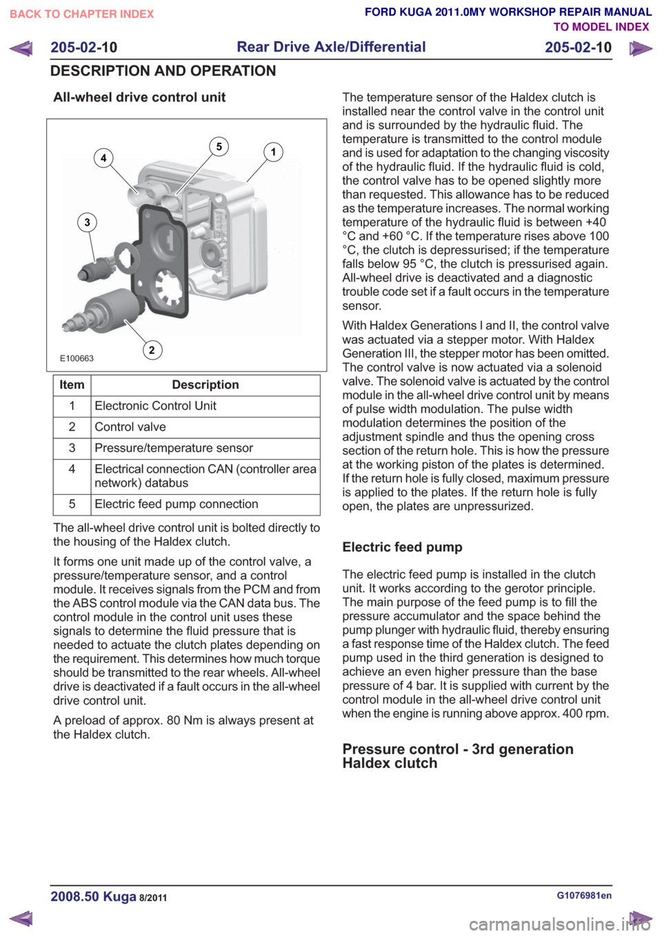
All-wheel drive control unit
E100663
14
3
2
5
Description
Item
Electronic Control Unit
1
Control valve
2
Pressure/temperature sensor
3
Electrical connection CAN (controller area
network) databus
4
Electric feed pump connection
5
The all-wheel drive control unit is bolted directly to
the housing of the Haldex clutch.
It forms one unit made up of the control valve, a
pressure/temperature sensor, and a control
module. It receives signals from the PCM and from
the ABS control module via the CAN data bus. The
control module in the control unit uses these
signals to determine the fluid pressure that is
needed to actuate the clutch plates depending on
the requirement. This determines how much torque
should be transmitted to the rear wheels. All-wheel
drive is deactivated if a fault occurs in the all-wheel
drive control unit.
A preload of approx. 80 Nm is always present at
the Haldex clutch. The temperature sensor of the Haldex clutch is
installed near the control valve in the control unit
and is surrounded by the hydraulic fluid. The
temperature is transmitted to the control module
and is used for adaptation to the changing viscosity
of the hydraulic fluid. If the hydraulic fluid is cold,
the control valve has to be opened slightly more
than requested. This allowance has to be reduced
as the temperature increases. The normal working
temperature of the hydraulic fluid is between +40
°C and +60 °C. If the temperature rises above 100
°C, the clutch is depressurised; if the temperature
falls below 95 °C, the clutch is pressurised again.
All-wheel drive is deactivated and a diagnostic
trouble code set if a fault occurs in the temperature
sensor.
With Haldex Generations I and II, the control valve
was actuated via a stepper motor. With Haldex
Generation III, the stepper motor has been omitted.
The control valve is now actuated via a solenoid
valve. The solenoid valve is actuated by the control
module in the all-wheel drive control unit by means
of pulse width modulation. The pulse width
modulation determines the position of the
adjustment spindle and thus the opening cross
section of the return hole. This is how the pressure
at the working piston of the plates is determined.
If the return hole is fully closed, maximum pressure
is applied to the plates. If the return hole is fully
open, the plates are unpressurized.
Electric feed pump
The electric feed pump is installed in the clutch
unit. It works according to the gerotor principle.
The main purpose of the feed pump is to fill the
pressure accumulator and the space behind the
pump plunger with hydraulic fluid, thereby ensuring
a fast response time of the Haldex clutch. The feed
pump used in the third generation is designed to
achieve an even higher pressure than the base
pressure of 4 bar. It is supplied with current by the
control module in the all-wheel drive control unit
when the engine is running above approx. 400 rpm.
Pressure control - 3rd generation
Haldex clutch
G1076981en2008.50 Kuga8/2011
205-02-
10
Rear Drive Axle/Differential
205-02- 10
DESCRIPTION AND OPERATION
TO MODEL INDEX
BACK TO CHAPTER INDEX
FORD KUGA 2011.0MY WORKSHOP REPAIR MANUAL
Page 1341 of 2057
narrow the cause to a specific component or condition.
Symptom Chart
Action
Possible Sources
Symptom
• INSTALL new brake shoes orbrake pads.
REFER to: Brake Pads (206-03
Front Disc Brake, Removal
and Installation).
• Worn or damaged brake shoes
or brake pads and linings.
• Brakes pull or drift
• INSTALL a new front brakedisc.
REFER to: Brake Caliper (206-
03 Front Disc Brake,
Removal and Installation).
• Abnormal wear or distortion of
front brake disc.
• ADJUST the parking brakecable.
REFER to: Parking Brake
Cable Adjustment (206-05
Parking Brake and Actuation,
General Procedures).
• Incorrect rear brake adjust-
ment.
• ADJUST the wheel alignment.REFER to: (204-00 Suspension
System - General Information)
Front Toe Adjustment (General
Procedures),
Rear Toe Adjustment (General
Procedures).
• Incorrect wheel alignment
adjustment.
• ADJUST or INSTALL a newwheel bearing.
REFER to: Front Wheel
Bearing (204-01 Front
Suspension, Removal and
Installation).
• Incorrect wheel bearing preload
adjustment.
• INSTALL new brake shoes orbrake pads.
REFER to: Brake Pads (206-03
Front Disc Brake, Removal
and Installation).
• Grease or fluid on the brake
shoes or brake pads; glazed
linings.
• INSTALL a new wheel cylinderor brake caliper.
REFER to: Brake Caliper (206-
04 Rear Disc Brake, Removal
and Installation).
• Stuck or seized wheel cylinders
or brake calipers.
• FILL the reservoir. CHECK thebrake and clutch system for
leaks including brake fluid in
the brake booster.
• Low brake fluid level.
• The red brake warning indicator
is always on
G1058975en2008.50 Kuga8/2011
206-00- 5
Brake System - General Information
206-00- 5
DIAGNOSIS AND TESTING
TO MODEL INDEX
BACK TO CHAPTER INDEX
FORD KUGA 2011.0MY WORKSHOP REPAIR MANUAL
Page 1782 of 2057
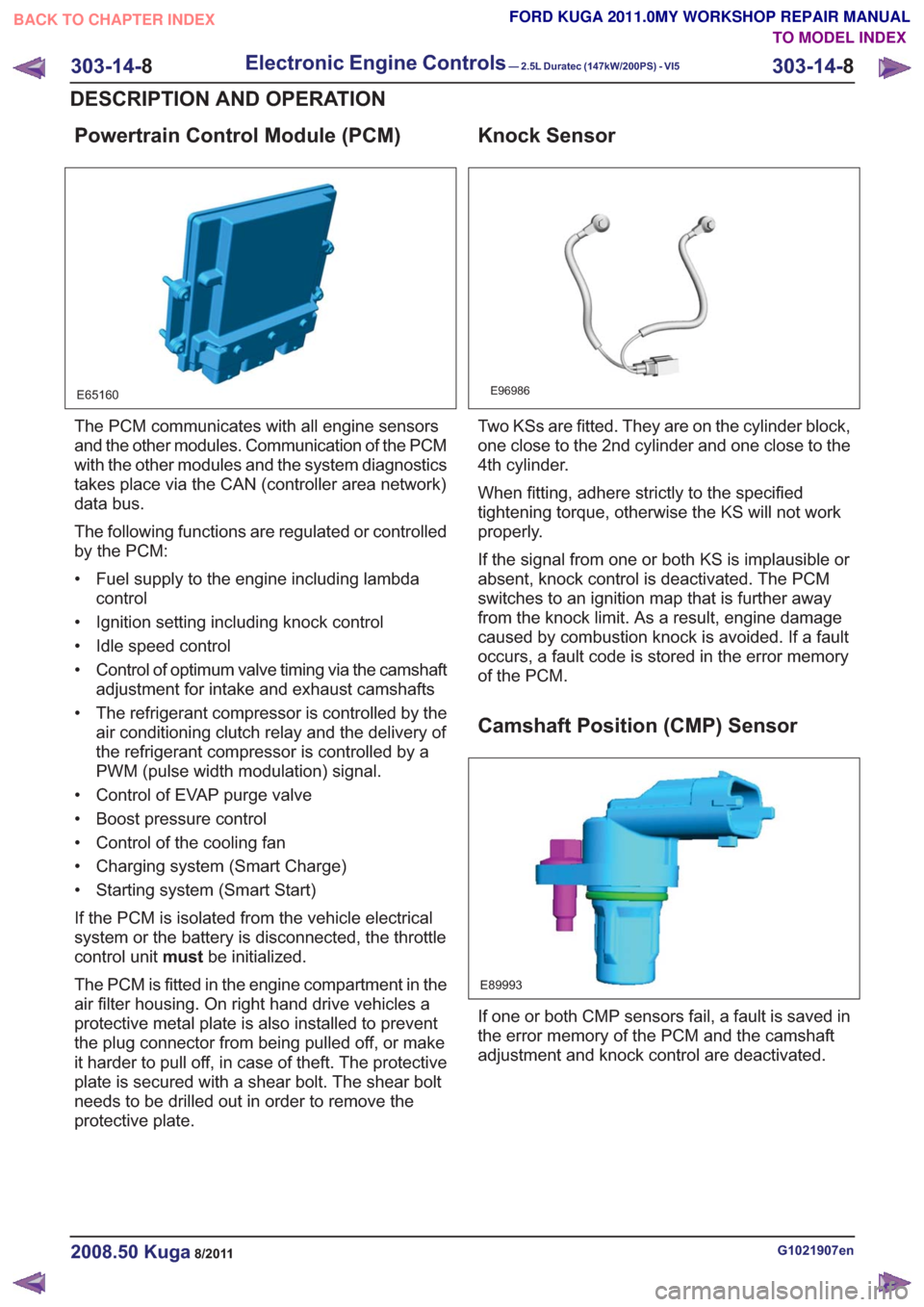
Powertrain Control Module (PCM)
E65160
The PCM communicates with all engine sensors
and the other modules. Communication of the PCM
with the other modules and the system diagnostics
takes place via the CAN (controller area network)
data bus.
The following functions are regulated or controlled
by the PCM:
• Fuel supply to the engine including lambdacontrol
• Ignition setting including knock control
• Idle speed control
• Control of optimum valve timing via the camshaft adjustment for intake and exhaust camshafts
• The refrigerant compressor is controlled by the air conditioning clutch relay and the delivery of
the refrigerant compressor is controlled by a
PWM (pulse width modulation) signal.
• Control of EVAP purge valve
• Boost pressure control
• Control of the cooling fan
• Charging system (Smart Charge)
• Starting system (Smart Start)
If the PCM is isolated from the vehicle electrical
system or the battery is disconnected, the throttle
control unit mustbe initialized.
The PCM is fitted in the engine compartment in the
air filter housing. On right hand drive vehicles a
protective metal plate is also installed to prevent
the plug connector from being pulled off, or make
it harder to pull off, in case of theft. The protective
plate is secured with a shear bolt. The shear bolt
needs to be drilled out in order to remove the
protective plate.
Knock Sensor
E96986
Two KSs are fitted. They are on the cylinder block,
one close to the 2nd cylinder and one close to the
4th cylinder.
When fitting, adhere strictly to the specified
tightening torque, otherwise the KS will not work
properly.
If the signal from one or both KS is implausible or
absent, knock control is deactivated. The PCM
switches to an ignition map that is further away
from the knock limit. As a result, engine damage
caused by combustion knock is avoided. If a fault
occurs, a fault code is stored in the error memory
of the PCM.
Camshaft Position (CMP) Sensor
E89993
If one or both CMP sensors fail, a fault is saved in
the error memory of the PCM and the camshaft
adjustment and knock control are deactivated.
G1021907en2008.50 Kuga8/2011
303-14- 8
Electronic Engine Controls— 2.5L Duratec (147kW/200PS) - VI5303-14-
8
DESCRIPTION AND OPERATION
TO MODEL INDEX
BACK TO CHAPTER INDEX
FORD KUGA 2011.0MY WORKSHOP REPAIR MANUAL
Page 1790 of 2057
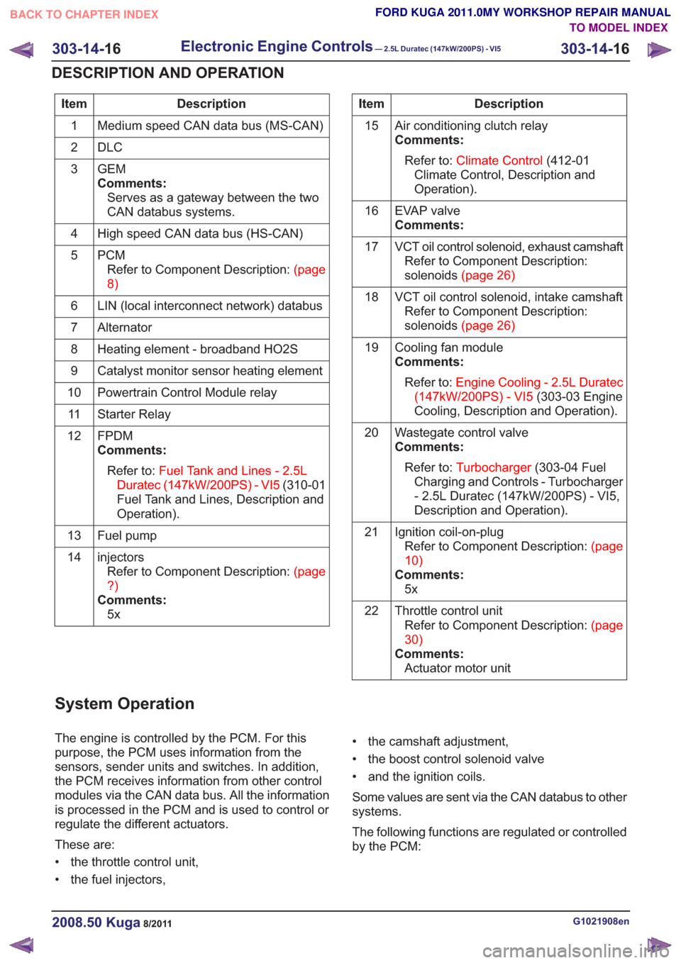
Description
Item
Medium speed CAN data bus (MS-CAN)
1
DLC
2
GEM
Comments:Serves as a gateway between the two
CAN databus systems.
3
High speed CAN data bus (HS-CAN)
4
PCMRefertoComponentDescription:(page
8)
5
LIN (local interconnect network) databus
6
Alternator
7
Heating element - broadband HO2S
8
Catalyst monitor sensor heating element
9
Powertrain Control Module relay
10
Starter Relay
11
FPDM
Comments:Refer to: Fuel Tank and Lines - 2.5L
Duratec (147kW/200PS) - VI5 (310-01
Fuel Tank and Lines, Description and
Operation).
12
Fuel pump
13
injectorsRefertoComponentDescription:(page
?)
Comments: 5x
14Description
Item
Air conditioning clutch relay
Comments:Refer to: Climate Control (412-01
Climate Control, Description and
Operation).
15
EVAP valve
Comments:
16
VCT oil control solenoid, exhaust camshaftRefer to Component Description:
solenoids(page26)
17
VCT oil control solenoid, intake camshaftRefer to Component Description:
solenoids(page26)
18
Cooling fan module
Comments:Refer to: Engine Cooling - 2.5L Duratec
(147kW/200PS) - VI5 (303-03 Engine
Cooling, Description and Operation).
19
Wastegate control valve
Comments:Refer to: Turbocharger (303-04 Fuel
Charging and Controls - Turbocharger
- 2.5L Duratec (147kW/200PS) - VI5,
Description and Operation).
20
Ignition coil-on-plugRefertoComponentDescription:(page
10)
Comments: 5x
21
Throttle control unitRefertoComponentDescription:(page
30)
Comments: Actuator motor unit
22
System Operation
The engine is controlled by the PCM. For this
purpose, the PCM uses information from the
sensors, sender units and switches. In addition,
the PCM receives information from other control
modules via the CAN data bus. All the information
is processed in the PCM and is used to control or
regulate the different actuators.
These are:
• the throttle control unit,
• the fuel injectors, • the camshaft adjustment,
• the boost control solenoid valve
• and the ignition coils.
Some values are sent via the CAN databus to other
systems.
The following functions are regulated or controlled
by the PCM:
G1021908en2008.50 Kuga8/2011
303-14-
16
Electronic Engine Controls— 2.5L Duratec (147kW/200PS) - VI5303-14-
16
DESCRIPTION AND OPERATION
TO MODEL INDEX
BACK TO CHAPTER INDEX
FORD KUGA 2011.0MY WORKSHOP REPAIR MANUAL
Page 2012 of 2057
SECTION 412-00 Climate Control System - General
Information
VEHICLE APPLICATION:2008.50 Kuga
PA G E
CONTENTS
SPECIFICATIONS
412-00-2
Specifications ........................................................................\
..............................................
DIAGNOSIS AND TESTING 412-00-3
Climate Control System ........................................................................\
..............................
412-00-3
Inspection and Checking ........................................................................\
............................
412-00-3
Refrigerant Circuit - Quick Check ........................................................................\
...............
412-00-4
Sequence of A/C Request Signal ........................................................................\
...............
GENERAL PROCEDURES 412-00-6
Air Conditioning (A/C) System Flushing ........................................................................\
.....
412-00-7
Air Conditioning (A/C) System Recovery, Evacuation and Charging .................................
412-00-9
Spring Lock Coupling ........................................................................\
..................................
412-00-11
Air Conditioning (A/C) Clutch Air Gap Adjustment .............................................................
412-00-12
Refrigerant Oil Adding ........................................................................\
................................
412-00-13
Contaminated Refrigerant Handling ........................................................................\
...........
412-00-14
Electronic Leak Detection ........................................................................\
...........................
412-00-15
Fluorescent Dye Leak Detection ........................................................................\
................
412-00-16
Vacuum Leak Detection ........................................................................\
..............................
412-00-1
Climate Control System - General Information
412-00- 1
.
TO MODEL INDEX
BACK TO CHAPTER INDEX
FORD KUGA 2011.0MY WORKSHOP REPAIR MANUAL
Page 2022 of 2057
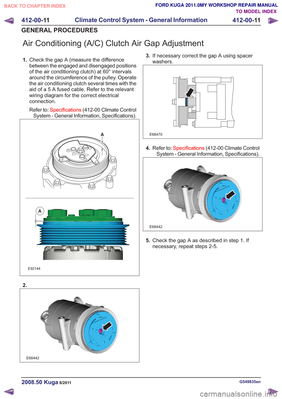
Air Conditioning (A/C) Clutch Air Gap Adjustment
1.Check the gap A (measure the difference
between the engaged and disengaged positions
of the air conditioning clutch) at 60° intervals
around the circumference of the pulley. Operate
the air conditioning clutch several times with the
aid of a 5 A fused cable. Refer to the relevant
wiring diagram for the correct electrical
connection.
Refer to: Specifications (412-00 Climate Control
System - General Information, Specifications).
E92144
A
2.
E68442
3. If necessary correct the gap A using spacer
washers.
E68470
4.Refer to: Specifications (412-00 Climate Control
System - General Information, Specifications).
E68442
5. Check the gap A as described in step 1. If
necessary, repeat steps 2-5.
G549835en2008.50 Kuga8/2011
412-00- 11
Climate Control System - General Information
412-00- 11
GENERAL PROCEDURES
TO MODEL INDEX
BACK TO CHAPTER INDEX
FORD KUGA 2011.0MY WORKSHOP REPAIR MANUAL