Page 1257 of 2057
E100540
Description
Item
Barometric Pressure
A
Base pressure
BDescription
Item
Increased base pressure (preload)
C
Operating pressure
Drive
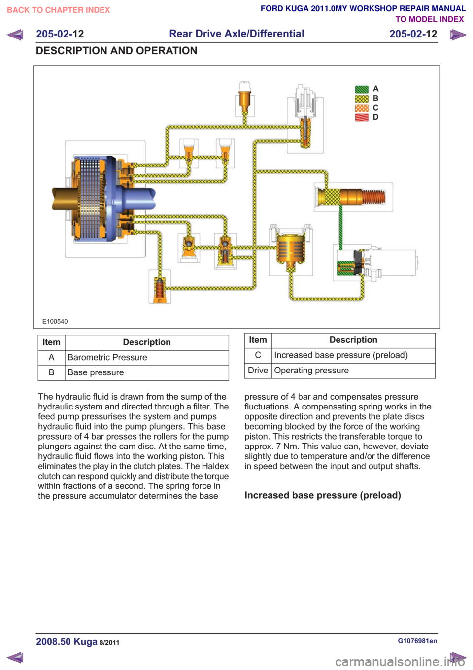
The hydraulic fluid is drawn from the sump of the
hydraulic system and directed through a filter. The
feed pump pressurises the system and pumps
hydraulic fluid into the pump plungers. This base
pressure of 4 bar presses the rollers for the pump
plungers against the cam disc. At the same time,
hydraulic fluid flows into the working piston. This
eliminates the play in the clutch plates. The Haldex
clutch can respond quickly and distribute the torque
within fractions of a second. The spring force in
the pressure accumulator determines the base pressure of 4 bar and compensates pressure
fluctuations. A compensating spring works in the
opposite direction and prevents the plate discs
becoming blocked by the force of the working
piston. This restricts the transferable torque to
approx. 7 Nm. This value can, however, deviate
slightly due to temperature and/or the difference
in speed between the input and output shafts.
Increased base pressure (preload)
G1076981en2008.50 Kuga8/2011
205-02-
12
Rear Drive Axle/Differential
205-02- 12
DESCRIPTION AND OPERATION
TO MODEL INDEX
BACK TO CHAPTER INDEX
FORD KUGA 2011.0MY WORKSHOP REPAIR MANUAL
Page 1258 of 2057
E100541
Description
Item
Barometric Pressure
A
Base pressure
BDescription
Item
Increased base pressure (preload)
C
Operating pressure
Drive
To ensure very fast torque transmission, a higher
voltage is applied to the electric feed pump and
the control valve fully closed before the shaft-driven
pump is brought into operation. As a result, the
maximum pressure is raised above the base
pressure, and a torque of up to 80 Nm applied to
the multi-plate clutch. This achieves significantly
faster pressure build-up than with older systems (second generation). To protect the pump from
overloading, the pressure is restricted to approx.
10 bar by the pressure relief valve. The hydraulic
fluid flows back into the sump via the pressure
accumulator.
Pressure build-up
G1076981en2008.50 Kuga8/2011
205-02-
13
Rear Drive Axle/Differential
205-02- 13
DESCRIPTION AND OPERATION
TO MODEL INDEX
BACK TO CHAPTER INDEX
FORD KUGA 2011.0MY WORKSHOP REPAIR MANUAL
Page 1259 of 2057
E100542
Description
Item
Barometric Pressure
A
Base pressure
BDescription
Item
Increased base pressure (preload)
C
Operating pressure
Drive
The pump plungers generate the operating
pressure that is controlled by the control valve as
a function of the difference in speed between the
input and output shafts. The control valve works
progressively from fully open to fully closed. The
fluid pressure can be approx. 67 bar when the
control valve is fully open. The maximum pressure is mechanically controlled by means of the
pressure relief valve.
Design of the 4th generation Haldex
clutch
General overview
G1076981en2008.50 Kuga8/2011
205-02-
14
Rear Drive Axle/Differential
205-02- 14
DESCRIPTION AND OPERATION
TO MODEL INDEX
BACK TO CHAPTER INDEX
FORD KUGA 2011.0MY WORKSHOP REPAIR MANUAL
Page 1260 of 2057
1
2
3
4
E115887
Description
Item
Fluid filter
1
All-wheel drive control unit
2Description
Item
Electric feed pump
3
Pressure accumulator
4
The electric feed pump is an axial piston pump
which is more robustly designed than the gerotor
pump in the 3rd generation Haldex. The higher
feed pressure means that the ring piston pump at
the clutch plate assembly, the pressure relief
valves, preload valve and the high pressure valves
are no longer necessary.
The pressure accumulator on the 4th generation
Haldex is larger and is designed for the higher
pressure. The 4th generation Haldex has a larger fluid filter
which contains a non-return valve.
The all-wheel drive control unit no longer contains
a pressure sensor in the 4th generation Haldex.
Pressure control - 4th generation Haldex
clutch
G1076981en2008.50 Kuga8/2011
205-02-
15
Rear Drive Axle/Differential
205-02- 15
DESCRIPTION AND OPERATION
TO MODEL INDEX
BACK TO CHAPTER INDEX
FORD KUGA 2011.0MY WORKSHOP REPAIR MANUAL
Page 1261 of 2057
6
7
8
9
10
11
1
2
3
4
5
6
7
8
9
10
11
E114914
Description
Item
Haldex clutch fluid
1
Inlet filter
2
Electric feed pump
3
Filters4
Pressure accumulator
5Description
Item
Control valve
6
Dished washer
7
Ring piston
8
Clutch plate pack
9
Return pressure accumulator
10
Return control valve
11
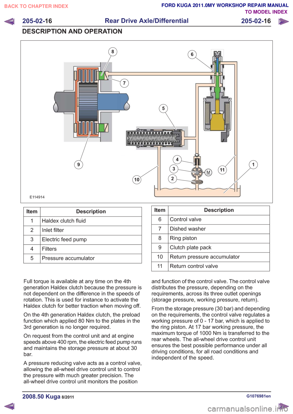
Full torque is available at any time on the 4th
generation Haldex clutch because the pressure is
not dependent on the difference in the speeds of
rotation. This is used for instance to activate the
Haldex clutch for better traction when moving off.
On the 4th generation Haldex clutch, the preload
function which applied 80 Nm to the plates in the
3rd generation is no longer required.
On request from the control unit and at engine
speeds above 400 rpm, the electric feed pump runs
and maintains the storage pressure at about 30
bar.
A pressure reducing valve acts as a control valve,
allowing the all-wheel drive control unit to control
the pressure with much greater precision. The
all-wheel drive control unit monitors the position and function of the control valve. The control valve
distributes the pressure, depending on the
requirements, across its three outlet openings
(storage pressure, working pressure, return).
From the storage pressure (30 bar) and depending
on the requirements, the control valve regulates a
working pressure of 0 - 17 bar, which is applied to
the ring piston. At 17 bar working pressure, the
maximum torque of 1000 Nm is transferred to the
rear wheels. The all-wheel drive control unit
ensures the best possible performance under all
driving conditions, for all road conditions and
independent of the speed.
G1076981en2008.50 Kuga8/2011
205-02-
16
Rear Drive Axle/Differential
205-02- 16
DESCRIPTION AND OPERATION
TO MODEL INDEX
BACK TO CHAPTER INDEX
FORD KUGA 2011.0MY WORKSHOP REPAIR MANUAL
Page 1296 of 2057
SECTION 205-04 Front Drive Halfshafts
VEHICLE APPLICATION:2008.50 Kuga
PA G E
CONTENTS
SPECIFICATIONS
205-04-2
Specifications ........................................................................\
..............................................
DIAGNOSIS AND TESTING 205-04-3
Front Drive Halfshafts ........................................................................\
.................................
205-04-3
Inspection and Verification ........................................................................\
..........................
REMOVAL AND INSTALLATION 205-04-5
(14 320 0)
Front Halfshaft LH ........................................................................\
..................
205-04-16
(14 321 0)
Front Halfshaft RH — LHD 4WD/RHD 4WD ..................................................
205-04-27
(14 336 0)
Inner Constant Velocity (CV) Joint Boot .........................................................
205-04-30
(14 338 0)
Outer Constant Velocity (CV) Joint Boot ........................................................
205-04-31
Halfshaft Bearing ........................................................................\
........................................
205-04-1
Front Drive Halfshafts
205-04- 1
.
TO MODEL INDEX
BACK TO CHAPTER INDEX
FORD KUGA 2011.0MY WORKSHOP REPAIR MANUAL
Page 1297 of 2057
Lubricants, Fluids, Sealers and Adhesives
Specifications
WSS-M1C 259-A1
Outer Constant Velocity Joint
Grease
Specifications
WSS-M1C 259-A1
Inner Constant Velocity Joint Grease
Capacity
Driveshaft Joint Grease Fill Capacity
Description
Outer (Grams)
Inner (Grams)
180
160
2.0 L Duratorq
2.5 L Duratec
Torque Specifications
lb-in
lb-ft
Nm
Item
-
35
48
2.0 L Duratorq - Intermediate shaft center bearing
bracket to engine block bolts - 2WD (M10x 30)
35
48
2.0 L Duratorq - Intermediate shaft center bearing
bracket to engine block bolts - 4WD (M10x 30)
-
44
60
2.0 L Duratorq - Intermediate shaft center bearing
bracket to engine block bolt - 4WD (M10x 40)
-
35
48
2.5 L Duratec - Intermediate shaft center bearing
bracket to engine block bolts - 4WD (M10x 30)
-
44
60
2.5 L Duratec - Intermediate shaft center bearing
bracket to engine block bolt - 4WD (M10x 40)
G1081400en2008.50 Kuga8/2011
205-04- 2
Front Drive Halfshafts
205-04- 2
SPECIFICATIONS
TO MODEL INDEX
BACK TO CHAPTER INDEX
FORD KUGA 2011.0MY WORKSHOP REPAIR MANUAL
Page 1298 of 2057
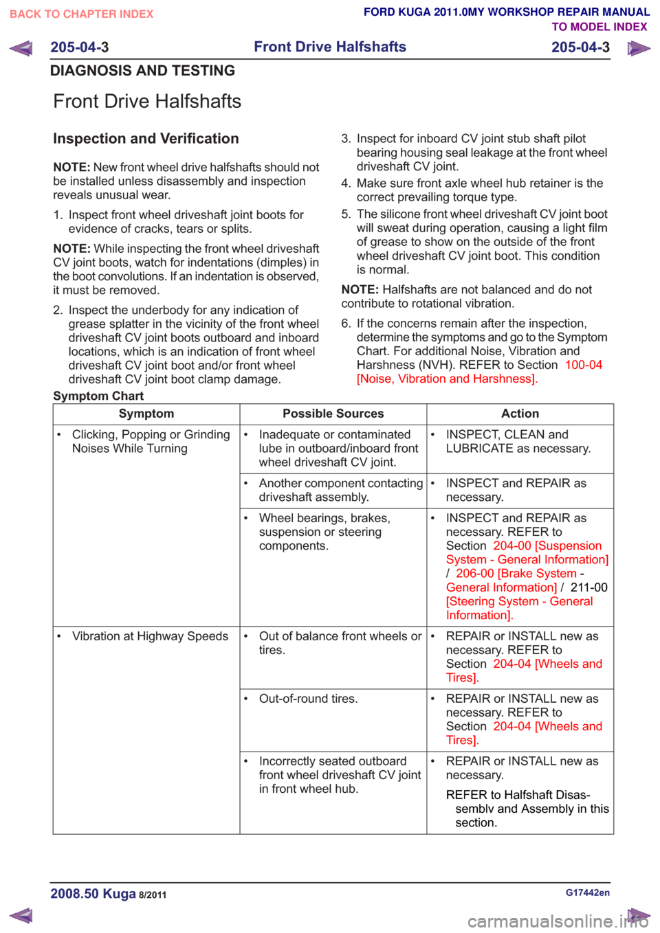
Front Drive Halfshafts
Inspection and Verification
NOTE:New front wheel drive halfshafts should not
be installed unless disassembly and inspection
reveals unusual wear.
1. Inspect front wheel driveshaft joint boots for evidence of cracks, tears or splits.
NOTE: While inspecting the front wheel driveshaft
CV joint boots, watch for indentations (dimples) in
the boot convolutions. If an indentation is observed,
it must be removed.
2. Inspect the underbody for any indication of grease splatter in the vicinity of the front wheel
driveshaft CV joint boots outboard and inboard
locations, which is an indication of front wheel
driveshaft CV joint boot and/or front wheel
driveshaft CV joint boot clamp damage. 3. Inspect for inboard CV joint stub shaft pilot
bearing housing seal leakage at the front wheel
driveshaft CV joint.
4. Make sure front axle wheel hub retainer is the correct prevailing torque type.
5. The silicone front wheel driveshaft CV joint boot will sweat during operation, causing a light film
of grease to show on the outside of the front
wheel driveshaft CV joint boot. This condition
is normal.
NOTE: Halfshafts are not balanced and do not
contribute to rotational vibration.
6. If the concerns remain after the inspection, determine the symptoms and go to the Symptom
Chart. For additional Noise, Vibration and
Harshness (NVH). REFER to Section 100-04
[Noise, Vibration and Harshness] .
Symptom Chart
Action
Possible Sources
Symptom
• INSPECT, CLEAN andLUBRICATE as necessary.
• Inadequate or contaminated
lube in outboard/inboard front
wheel driveshaft CV joint.
• Clicking, Popping or Grinding
Noises While Turning
• INSPECT and REPAIR asnecessary.
• Another component contacting
driveshaft assembly.
• INSPECT and REPAIR asnecessary. REFER to
Section 204-00 [Suspension
System - General Information]
/ 206-00 [Brake System -
General Information] /211-00
[Steering System - General
Information] .
• Wheel bearings, brakes,
suspension or steering
components.
• REPAIR or INSTALL new asnecessary. REFER to
Section 204-04 [Wheels and
Tires] .
• Out of balance front wheels or
tires.
• Vibration at Highway Speeds
• REPAIR or INSTALL new asnecessary. REFER to
Section 204-04 [Wheels and
Tires] .
• Out-of-round tires.
• REPAIR or INSTALL new asnecessary.
REFER to Halfshaft Disas-
semblv and Assembly in this
section.
• Incorrectly seated outboard
front wheel driveshaft CV joint
in front wheel hub.
G17442en2008.50 Kuga8/2011
205-04- 3
Front Drive Halfshafts
205-04- 3
DIAGNOSIS AND TESTING
TO MODEL INDEX
BACK TO CHAPTER INDEX
FORD KUGA 2011.0MY WORKSHOP REPAIR MANUAL