2011 FORD KUGA AIR CON
[x] Cancel search: AIR CONPage 1229 of 2057
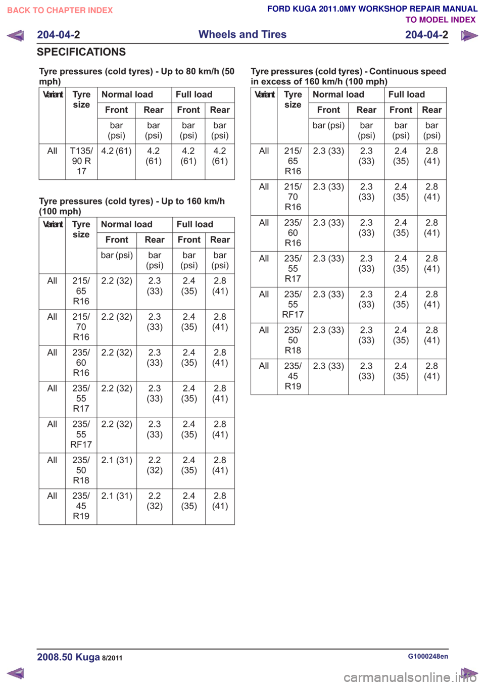
Tyre pressures (cold tyres) - Up to 80 km/h (50
mph)
Full load
Normal load
Tyre
size
Variant
Rear
Front
Rear
Front
bar
(psi)
bar
(psi)
bar
(psi)
bar
(psi)
4.2
(61)
4.2
(61)
4.2
(61)
4.2 (61)
T135/
90 R 17
All
Tyre pressures (cold tyres) - Up to 160 km/h
(100 mph)
Full load
Normal load
Tyre
size
Variant
Rear
Front
Rear
Front
bar
(psi)
bar
(psi)
bar
(psi)
bar (psi)
2.8
(41)
2.4
(35)
2.3
(33)
2.2 (32)
215/
65
R16
All
2.8
(41)
2.4
(35)
2.3
(33)
2.2 (32)
215/
70
R16
All
2.8
(41)
2.4
(35)
2.3
(33)
2.2 (32)
235/
60
R16
All
2.8
(41)
2.4
(35)
2.3
(33)
2.2 (32)
235/
55
R17
All
2.8
(41)
2.4
(35)
2.3
(33)
2.2 (32)
235/
55
RF17
All
2.8
(41)
2.4
(35)
2.2
(32)
2.1 (31)
235/
50
R18
All
2.8
(41)
2.4
(35)
2.2
(32)
2.1 (31)
235/
45
R19
All Tyre pressures (cold tyres) - Continuous speed
in excess of 160 km/h (100 mph)
Full load
Normal load
Tyre
size
Variant
Rear
Front
Rear
Front
bar
(psi)
bar
(psi)
bar
(psi)
bar (psi)
2.8
(41)
2.4
(35)
2.3
(33)
2.3 (33)
215/
65
R16
All
2.8
(41)
2.4
(35)
2.3
(33)
2.3 (33)
215/
70
R16
All
2.8
(41)
2.4
(35)
2.3
(33)
2.3 (33)
235/
60
R16
All
2.8
(41)
2.4
(35)
2.3
(33)
2.3 (33)
235/
55
R17
All
2.8
(41)
2.4
(35)
2.3
(33)
2.3 (33)
235/
55
RF17
All
2.8
(41)
2.4
(35)
2.3
(33)
2.3 (33)
235/
50
R18
All
2.8
(41)
2.4
(35)
2.3
(33)
2.3 (33)
235/
45
R19
All
G1000248en2008.50 Kuga8/2011
204-04-
2
Wheels and Tires
204-04- 2
SPECIFICATIONS
TO MODEL INDEX
BACK TO CHAPTER INDEX
FORD KUGA 2011.0MY WORKSHOP REPAIR MANUAL
Page 1230 of 2057
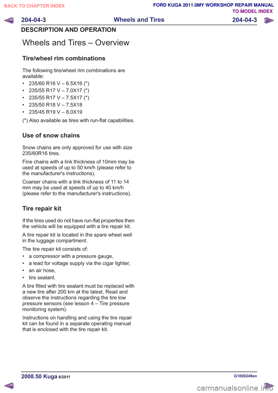
Wheels and Tires – Overview
Tire/wheel rim combinations
The following tire/wheel rim combinations are
available:
• 235/60 R16 V – 6.5X16 (*)
• 235/55 R17 V – 7.0X17 (*)
• 235/55 R17 V – 7.5X17 (*)
• 235/50 R18 V – 7.5X18
• 235/45 R19 V – 8.0X19
(*) Also available as tires with run-flat capabilities.
Use of snow chains
Snow chains are only approved for use with size
235/60R16 tires.
Fine chains with a link thickness of 10mm may be
used at speeds of up to 50 km/h (please refer to
the manufacturer's instructions).
Coarser chains with a link thickness of 11 to 14
mm may be used at speeds of up to 40 km/h
(please refer to the manufacturer's instructions).
Tire repair kit
If the tires used do not have run-flat properties then
the vehicle will be equipped with a tire repair kit.
A tire repair kit is located in the spare wheel well
in the luggage compartment.
The tire repair kit consists of:
• a compressor with a pressure gauge,
• a lead for voltage supply via the cigar lighter,
• an air hose,
• tire sealant.
A tire filled with tire sealant must be replaced with
a new tire after 200 km at the latest. Read and
observe the instructions regarding the tire low
pressure sensors (see lesson 4 – Tire pressure
monitoring system).
Instructions on handling and using the tire repair
kit can be found in a separate operating manual
that is enclosed with the tire repair kit.
G1000249en2008.50 Kuga8/2011
204-04-3
Wheels and Tires
204-04- 3
DESCRIPTION AND OPERATION
TO MODEL INDEX
BACK TO CHAPTER INDEX
FORD KUGA 2011.0MY WORKSHOP REPAIR MANUAL
Page 1232 of 2057
Tire Pressure Monitoring System (TPMS) – Overview
Description of operation
The tire pressure monitoring system is able to
detect loss of air in a tire at an early stage and warn
the driver. Because it can only compare the
behavior of the tires with each other, it is not
possible to draw conclusions about the absolute
tire pressure. It is also not possible to monitor the
spare tire pressure. In order for the system to
operate correctly, the tire pressures must be
regularly checked and corrected and the system
subsequently initialized (see below).
The tire pressure monitoring system used here,
depending on the equipment level, is built into the
anti-lock braking system (ABS) as an extra function
and therefore does not have its own sensors.
The ABS module determines the loss of pressure
in the tires by calculation using the wheel speed
sensors of the ABS system. If a tire loses pressure,
its diameter decreases and the speed of the wheel
therefore increases. If the ABS module detects
such a loss in pressure, it sends a signal to the
instrument cluster via the CAN bus and a warning
message is displayed in the driver information
system. The warning threshold depends among
other things on the dimension of the tires being
used, the vehicle operating conditions and the
status at the last initialization. Since neither the
absolute tire pressure nor the position of the tire is
known, after a tire pressure warning the pressure
of all the tires must be checked and the system
re-initialized. If necessary, the cause of the loss of
pressure must be investigated.
Furthermore, regular pressure checks are
necessary. The system must be initialized after a
tire is changed, winter or summer tires fitted, the
pressures corrected or adjusted to suit the vehicle
load. This can be done by the driver using the
driver information system. For further information,
see: Owner’s Manual.
G1001290en2008.50 Kuga8/2011
204-04-5
Wheels and Tires
204-04- 5
DESCRIPTION AND OPERATION
TO MODEL INDEX
BACK TO CHAPTER INDEX
FORD KUGA 2011.0MY WORKSHOP REPAIR MANUAL
Page 1233 of 2057
Wheels and Tires
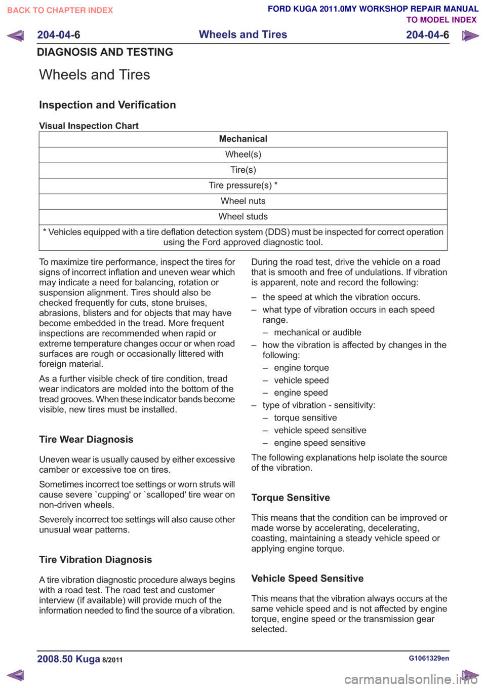
Inspection and Verification
Visual Inspection Chart
MechanicalWheel(s)Tire(s)
Tire pressure(s) * Wheel nuts
Wheel studs
* Vehicles equipped with a tire deflation detection system (DDS) must be inspected for correct operation using the Ford approved diagnostic tool.
To maximize tire performance, inspect the tires for
signs of incorrect inflation and uneven wear which
may indicate a need for balancing, rotation or
suspension alignment. Tires should also be
checked frequently for cuts, stone bruises,
abrasions, blisters and for objects that may have
become embedded in the tread. More frequent
inspections are recommended when rapid or
extreme temperature changes occur or when road
surfaces are rough or occasionally littered with
foreign material.
As a further visible check of tire condition, tread
wear indicators are molded into the bottom of the
tread grooves. When these indicator bands become
visible, new tires must be installed.
Tire Wear Diagnosis
Uneven wear is usually caused by either excessive
camber or excessive toe on tires.
Sometimes incorrect toe settings or worn struts will
cause severe `cupping' or `scalloped' tire wear on
non-driven wheels.
Severely incorrect toe settings will also cause other
unusual wear patterns.
Tire Vibration Diagnosis
A tire vibration diagnostic procedure always begins
with a road test. The road test and customer
interview (if available) will provide much of the
information needed to find the source of a vibration. During the road test, drive the vehicle on a road
that is smooth and free of undulations. If vibration
is apparent, note and record the following:
– the speed at which the vibration occurs.
– what type of vibration occurs in each speed
range.
– mechanical or audible
– how the vibration is affected by changes in the following:
– engine torque
– vehicle speed
– engine speed
– type of vibration - sensitivity: – torque sensitive
– vehicle speed sensitive
– engine speed sensitive
The following explanations help isolate the source
of the vibration.
Torque Sensitive
This means that the condition can be improved or
made worse by accelerating, decelerating,
coasting, maintaining a steady vehicle speed or
applying engine torque.
Vehicle Speed Sensitive
This means that the vibration always occurs at the
same vehicle speed and is not affected by engine
torque, engine speed or the transmission gear
selected.
G1061329en2008.50 Kuga8/2011
204-04- 6
Wheels and Tires
204-04- 6
DIAGNOSIS AND TESTING
TO MODEL INDEX
BACK TO CHAPTER INDEX
FORD KUGA 2011.0MY WORKSHOP REPAIR MANUAL
Page 1234 of 2057
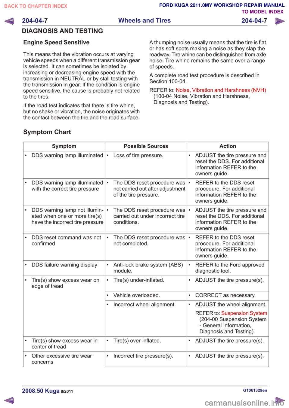
Engine Speed Sensitive
This means that the vibration occurs at varying
vehicle speeds when a different transmission gear
is selected. It can sometimes be isolated by
increasing or decreasing engine speed with the
transmission in NEUTRAL or by stall testing with
the transmission in gear. If the condition is engine
speed sensitive, the cause is probably not related
to the tires.
If the road test indicates that there is tire whine,
but no shake or vibration, the noise originates with
the contact between the tire and the road surface.A thumping noise usually means that the tire is flat
or has soft spots making a noise as they slap the
roadway. Tire whine can be distinguished from axle
noise. Tire whine remains the same over a range
of speeds.
A complete road test procedure is described in
Section 100-04.
REFER to:
Noise, Vibration and Harshness (NVH)
(100-04 Noise, Vibration and Harshness,
Diagnosis and Testing).
Symptom Chart
Action
Possible Sources
Symptom
• ADJUST the tire pressure andreset the DDS. For additional
information REFER to the
owners guide.
• Loss of tire pressure.
• DDS warning lamp illuminated
• REFER to the DDS resetprocedure. For additional
information REFER to the
owners guide.
• The DDS reset procedure was
not carried out after adjustment
of the tire pressure.
• DDS warning lamp illuminated
with the correct tire pressure
• ADJUST the tire pressure andreset the DDS. For additional
information REFER to the
owners guide.
• The DDS reset procedure was
carried out under incorrect tire
conditions.
• DDS warning lamp not illumin-
ated when one or more tire(s)
have the incorrect tire pressure
• REFER to the DDS resetprocedure. For additional
information REFER to the
owners guide.
• The DDS reset procedure was
not completed.
• DDS reset command was not
confirmed
• REFER to the Ford approveddiagnostic tool.
• Anti-lock brake system (ABS)
module.
• DDS failure warning display
• ADJUST the tire pressure(s).
• Tire(s) under-inflated.
• Tire(s) show excess wear on
edge of tread
• CORRECT as necessary.
• Vehicle overloaded.
• ADJUST the wheel alignment.REFER to: Suspension System
(204-00 Suspension System
- General Information,
Diagnosis and Testing).
• Incorrect wheel alignment.
• ADJUST the tire pressure(s).
• Tire(s) over-inflated.
• Tire(s) show excess wear in
center of tread
• ADJUST the tire pressure(s).
• Incorrect tire pressure(s).
• Other excessive tire wear
concerns
G1061329en2008.50 Kuga8/2011
204-04- 7
Wheels and Tires
204-04- 7
DIAGNOSIS AND TESTING
TO MODEL INDEX
BACK TO CHAPTER INDEX
FORD KUGA 2011.0MY WORKSHOP REPAIR MANUAL
Page 1237 of 2057
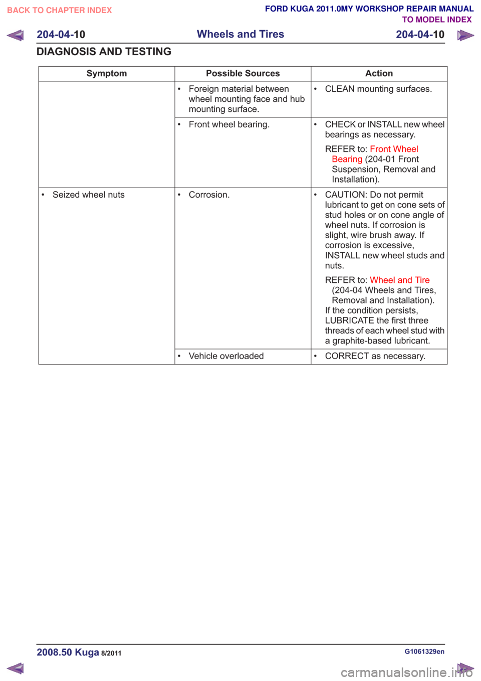
Action
Possible Sources
Symptom
• CLEAN mounting surfaces.
• Foreign material between
wheel mounting face and hub
mounting surface.
• CHECK or INSTALL new wheelbearings as necessary.
REFER to: Front Wheel
Bearing (204-01 Front
Suspension, Removal and
Installation).
• Front wheel bearing.
• CAUTION: Do not permitlubricant to get on cone sets of
stud holes or on cone angle of
wheel nuts. If corrosion is
slight, wire brush away. If
corrosion is excessive,
INSTALL new wheel studs and
nuts.
REFER to: Wheel and Tire
(204-04 Wheels and Tires,
Removal and Installation).
If the condition persists,
LUBRICATE the first three
threads of each wheel stud with
a graphite-based lubricant.
• Corrosion.
• Seized wheel nuts
• CORRECT as necessary.
• Vehicle overloaded
G1061329en2008.50 Kuga8/2011
204-04- 10
Wheels and Tires
204-04- 10
DIAGNOSIS AND TESTING
TO MODEL INDEX
BACK TO CHAPTER INDEX
FORD KUGA 2011.0MY WORKSHOP REPAIR MANUAL
Page 1239 of 2057
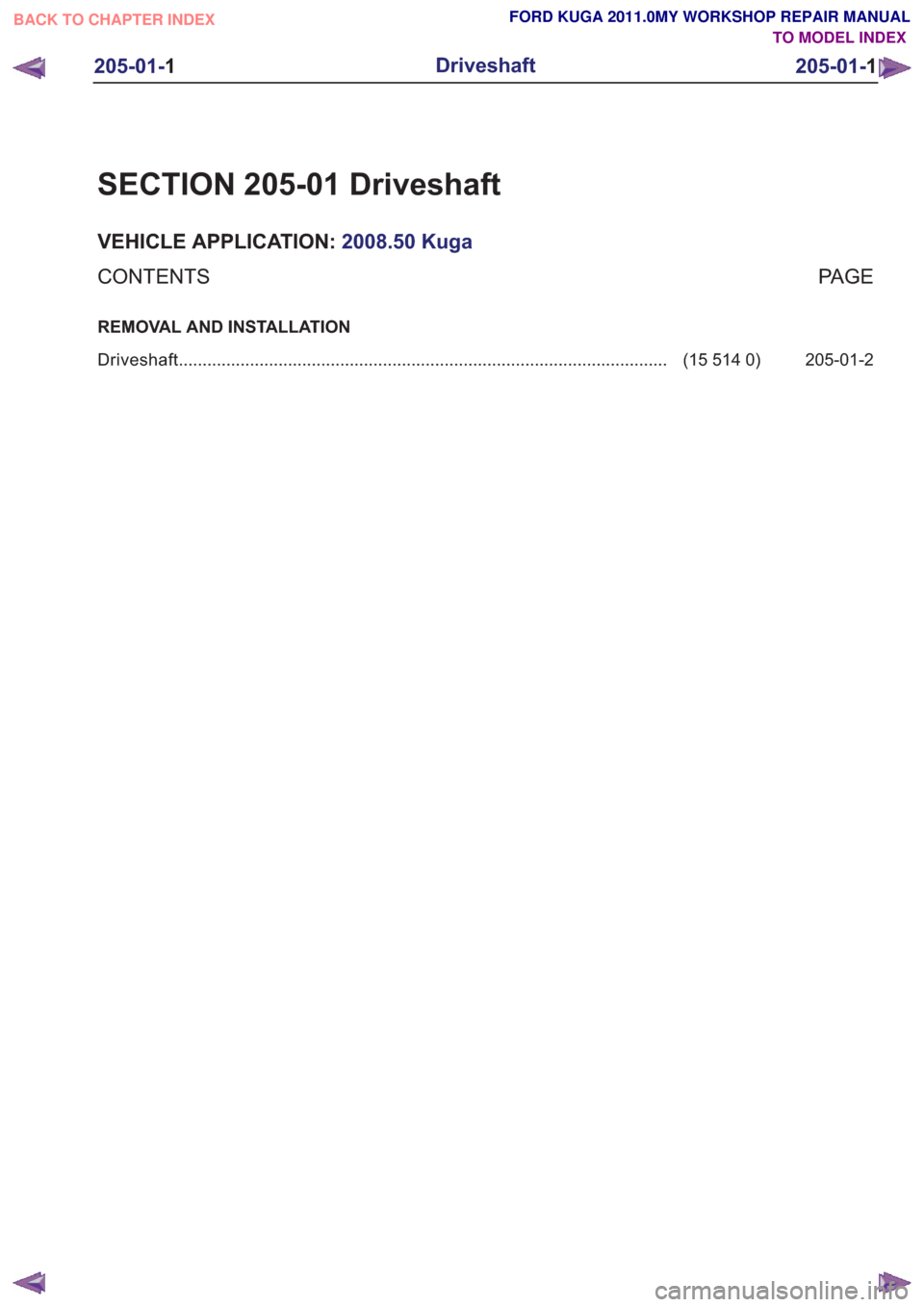
SECTION 205-01 Driveshaft
VEHICLE APPLICATION:2008.50 Kuga
PA G E
CONTENTS
REMOVAL AND INSTALLATION
205-01-2
(15 514 0)
Driveshaft ........................................................................\
...............................
205-01-1
Driveshaft
205-01- 1
.
TO MODEL INDEX
BACK TO CHAPTER INDEX
FORD KUGA 2011.0MY WORKSHOP REPAIR MANUAL
Page 1246 of 2057
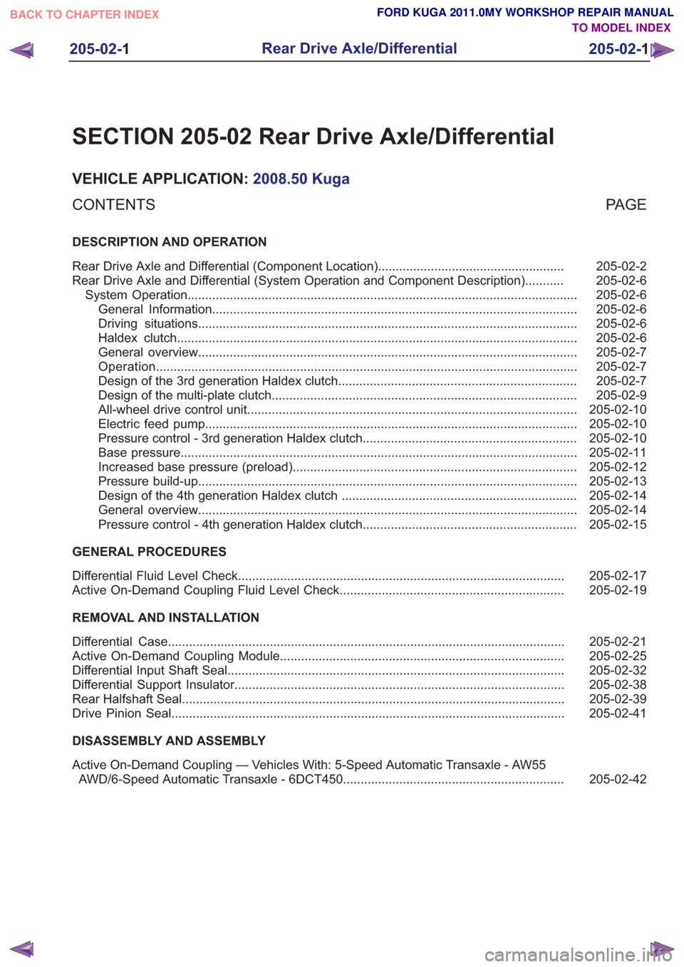
SECTION 205-02 Rear Drive Axle/Differential
VEHICLE APPLICATION:2008.50 Kuga
PA G E
CONTENTS
DESCRIPTION AND OPERATION
205-02-2
Rear Drive Axle and Differential (Component Location) .....................................................
205-02-6
Rear Drive Axle and Differential (System Operation and Component Description) ...........
205-02-6
System Operation ........................................................................\
.......................................
205-02-6
General Information ........................................................................\
................................
205-02-6
Driving situations ........................................................................\
....................................
205-02-6
Haldex clutch ........................................................................\
..........................................
205-02-7
General overview ........................................................................\
....................................
205-02-7
Operation ........................................................................\
................................................
205-02-7
Design of the 3rd generation Haldex clutch ....................................................................
205-02-9
Design of the multi-plate clutch ........................................................................\
...............
205-02-10
All-wheel drive control unit ........................................................................\
......................
205-02-10
Electric feed pump ........................................................................\
..................................
205-02-10
Pressure control - 3rd generation Haldex clutch .............................................................
205-02-11
Base pressure ........................................................................\
.........................................
205-02-12
Increased base pressure (preload) ........................................................................\
.........
205-02-13
Pressure build-up ........................................................................\
....................................
205-02-14
Design of the 4th generation Haldex clutch ...................................................................
205-02-14
General overview ........................................................................\
....................................
205-02-15
Pressure control - 4th generation Haldex clutch .............................................................
GENERAL PROCEDURES 205-02-17
Differential Fluid Level Check ........................................................................\
.....................
205-02-19
Active On-Demand Coupling Fluid Level Check ................................................................
REMOVAL AND INSTALLATION 205-02-21
Differential Case ........................................................................\
.........................................
205-02-25
Active On-Demand Coupling Module ........................................................................\
.........
205-02-32
Differential Input Shaft Seal ........................................................................\
........................
205-02-38
Differential Support Insulator ........................................................................\
......................
205-02-39
Rear Halfshaft Seal ........................................................................\
.....................................
205-02-41
Drive Pinion Seal ........................................................................\
........................................
DISASSEMBLY AND ASSEMBLY
205-02-42
Active On-Demand Coupling — Vehicles With: 5-Speed Automatic Transaxle - AW55
AWD/6-Speed Automatic Transaxle - 6DCT450 ...............................................................
205-02-1
Rear Drive Axle/Differential
205-02- 1
.
TO MODEL INDEX
BACK TO CHAPTER INDEX
FORD KUGA 2011.0MY WORKSHOP REPAIR MANUAL