2011 FORD KUGA AIR CON
[x] Cancel search: AIR CONPage 460 of 2057

Windshield wash/wipe system
Refer to:
Wipers and Washers (501-16 Wipers and
Washers, Description and Operation).
Anti-theft
Refer to: Anti-Theft - Active (419-01 Anti-Theft -
Active, Description and Operation).
Electric booster Heater
Refer to: Auxiliary Climate Control (412-02 Auxiliary
Climate Control, Description and Operation).
Climate control
Refer to: Climate Control (412-01 Climate Control,
Description and Operation). G1030788en
2008.50 Kuga 8/2011 419-10-10
Multifunction Electronic Modules
419-10-10
DESCRIPTION AND OPERATIONTO MODEL INDEX
BACK TO CHAPTER INDEX
FORD KUGA 2011.0MY WORKSHOP REPAIR MANUAL
Page 461 of 2057

Generic Electronic Module (GEM)
Refer to Wiring Diagrams Section 419-10, for
schematic and connector information.
Special Tool(s) / General Equipment
Terminal Probe Kit
418-S035Digital multimeter
Ford approved diagnostic tool
Description of operation
A diagnosis of the generic electronic module (GEM)
can be performed with the Ford approved
diagnostic tool. Furthermore, an integrated service
mode enables testing of the input and output
signals without the need for further tools. To enable
activation of service mode:
• Switch off the ignition
• Switch off all other electrical consumers
• Apply the handbrake
• Shift to neutral
• Close the doors.
Activate service mode
Proceed as follows to activate service mode:
• PRESS and HOLD the switch of the heated rear
window
• SWITCH ON the ignition.
• RELEASE the switch of the heated rear window
A signal sounds and the turn signal lamps
illuminate to indicate that service mode has been
successfully activated.
NOTE: If the alarm is armed (in vehicles fitted with
an anti-theft alarm system), service mode cannot
be activated.
Input signals
SWITCH the windshield wiper switch to the "Off"
position to test the input signals. The following is
a list of the switch signals to be tested, in no
particular order: • Turn signals (right, left, hazard warning lights)
• Windshield wiper stage I
• Windshield wiper stage II
• Windshield washer system
• Rear window wiper
• Rear window washer system
• Doors open/closed
• Door key cylinder set/reset switch
• Remote control for central locking with double
locking
• Hood up/down (in vehicles fitted with anti-theft alarm system)
• Tailgate open/closed
• Mini liftgate open/closed
• Manual A/C request signal
• Manual AUX heater request signal
• Heated windshield (if fitted)
• Parking brake
• Brake fluid level
• Cruise control system
• Autolamps
• Dipped beam
• Main beam
• Headlamp flasher
• Side lights
• Reversing lamp
• Tailgate release
• Mini liftgate release
• Interior scanning system
• Ignition switch, terminal 15 (turn key to 0 position, then turn key to II position.)
An acoustic signal sounds and the turn signal
lamps flash to indicate receipt of each input signal
by the generic electronic module.
Test the windshield wiper "intermittent mode" stage
input signal (only vehicles with adjustable
intermittent mode)
The windshield wiper switch must be switched to
"intermittent mode" in order to test the input signal.
The delay times of the input signals can then be
tested by operating the rotary switch. Each change
of the rotary switch position is indicated by an
acoustic signal and illumination of the turn signals. G1055084en
2008.50 Kuga 8/2011 419-10-11
Multifunction Electronic Modules
419-10-11
DIAGNOSIS AND TESTINGTO MODEL INDEX
BACK TO CHAPTER INDEX
FORD KUGA 2011.0MY WORKSHOP REPAIR MANUAL29011A
Page 462 of 2057

Output signals
SWITCH the wiper switch to the "intermittent""
position to test the output signals. PRESSING the
heated rear window switch activates the output
signals in the following order:
a.
Left-hand turn signal
b. Right-hand turn signal
c. Main beam
d. Dipped beam
e. Windshield wiper stage I
f. Windshield wiper stage II
g. Heated rear windshield
h. Heater blower motor
i. Headlamp washer system (vehicles with HID headlamps)
j. Electric booster heater (if fitted)
k. Autolamps (position lamps only if fitted)
l. Alarm horn (vehicles with alarm system)
m. Rear window wiper
n. Heated front window relay
When the heated rear window switch is pressed
again, the test of the relevant signal is terminated.
When the heated rear window switch is pressed
once more, the test for the next signal in the list is
started.
End service mode
The GEM automatically ends service mode 20
seconds after the last input or at a driving speed
of over 7km/h. However, service mode can be
manually ended at any time by proceeding as
follows:
• PRESS and HOLD the switch of the heated rear
window
• SWITCH OFF the ignition.
• RELEASE the switch of the heated rear window
3 signals sound and the turn signal lamps illuminate
to indicate that service mode has ended.
Reset service mode
If, after completion of service mode, some functions
do not operate or do not operate properly, check
the following functions:
• Instrument cluster illumination, side marker lamps (side lights) and licence plate lamp in
automatic headlamps mode
• Rear wiper
• Headlamp washer assembly
• Electric booster heater • Alarm horn
• Heated windshield
If one or more of the listed functions is not OK, it's
possible that the cause of the fault is due to not
exiting service mode properly. To reactivate the
functions correctly, perform the following steps:
1. Switch off the ignition.
2. SWITCH OFF the switch for the windscreen
wash/wipe system
3. OPERATE the switch of the heated rear window
and HOLD IT THERE
4. SWITCH ON the ignition.
5. RELEASE the heated rear window switch (an acoustic signal will sound if activation has been
performed correctly)
6. SWITCH the windscreen wash/wipe switch to the "Intermittent wipe" position
7. OPERATE the heated rear window switch 6 times (the main beam headlamps switch on and
off automatically)
8. SWITCH OFF the switch for the windscreen wash/wipe system
9. OPERATE the switch of the heated rear window
and HOLD IT THERE
10. Switch off the ignition.
11. RELEASE the heated rear window switch (three
acoustic signals will sound if activation has been
performed correctly)
After completion of the work, check all the
functions.
Inspection and Checking
NOTE: The generic electronic module (GEM) is
integrated into the central junction box (CJB).
1. VERIFY customer concern.
2. Visually CHECK for any obvious mechanical or electrical damage.
NOTE: Ensure correct locking of the wiring harness
connector.
Visual Inspection Electrical
Fuses
Wiring harness Connectors G1055084en
2008.50 Kuga 8/2011 419-10-12
Multifunction Electronic Modules
419-10-12
DIAGNOSIS AND TESTINGTO MODEL INDEX
BACK TO CHAPTER INDEX
FORD KUGA 2011.0MY WORKSHOP REPAIR MANUAL
Page 463 of 2057

3. If an obvious cause for an observed or reported
concern is found, correct the cause (if possible)
before proceeding to the next step.
4. If the cause is not visually evident, verify the symptom and refer to the diagnostic tab within
the Ford approved diagnostic tool. G1055084en
2008.50 Kuga 8/2011 419-10-13
Multifunction Electronic Modules
419-10-13
DIAGNOSIS AND TESTINGTO MODEL INDEX
BACK TO CHAPTER INDEX
FORD KUGA 2011.0MY WORKSHOP REPAIR MANUAL
Page 464 of 2057

Generic Electronic Module (GEM)
General Equipment
Ford Diagnostic Equipment
Removal
CAUTIONS: Modules must not be swapped between
vehicles.
Compare the number of relays and fuses
in the defective GEM and the new GEM.
Transfer from the defective GEM any relays
and fuses which are not in the new GEM.
In doing so, pay attention that fuses with
the correct Ampere rating are used, by
referring to the wiring diagrams.
When installing a new GEM on vehicles
with a diesel engine, make sure that a fuel
pump fuse (F111) with 5A is used.
When installing a new GEM on vehicles
with a petrol engine, make sure that a fuel
pump fuse (F111) with 15A is used.
NOTE: GEM is integrated into the central junction
box (CJB) and cannot be removed individually.
1. NOTE: This step is only necessary when
installing a new component.
Upload the GEM configuration information using
the Programmable Modules Installation Routine.
General Equipment: Ford Diagnostic Equipment
2. Refer to: Battery Disconnect and Connect
(414-01 Battery, Mounting and Cables,
General Procedures).
3. 4.
5.
Installation
1.
To install, reverse the removal procedure.
2. NOTE: This step is only necessary when
installing a new component.
Download the GEM configuration information
to the newly installed GEM using the
programmable modules installation routine.
3. NOTE: This step is only necessary when
installing a new component.
Program all keys using the Key Programming
Routine.
General Equipment: Ford Diagnostic Equipment G1065605en
2008.50 Kuga 8/2011 419-10-14
Multifunction Electronic Modules
419-10-14
REMOVAL AND INSTALLATIONTO MODEL INDEX
BACK TO CHAPTER INDEX
FORD KUGA 2011.0MY WORKSHOP REPAIR MANUALE51159 122E102019 E102020
Page 1158 of 2057

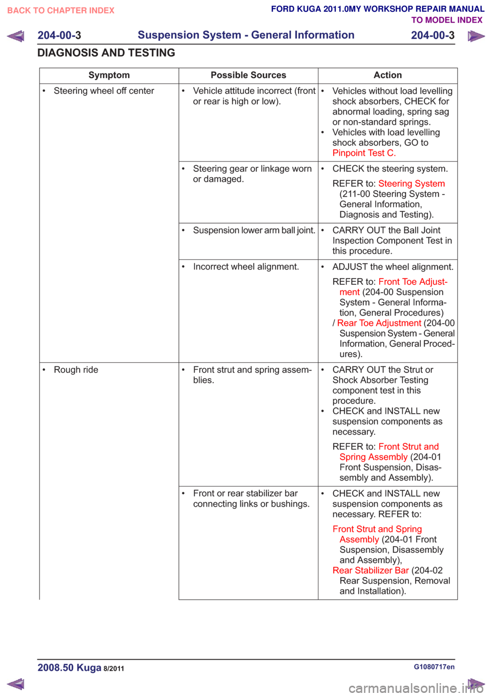
Action
Possible Sources
Symptom
• Vehicles without load levellingshock absorbers, CHECK for
abnormal loading, spring sag
or non-standard springs.
• Vehicles with load levelling shock absorbers, GO to
Pinpoint Test C.
• Vehicle attitude incorrect (front
or rear is high or low).
• Steering wheel off center
• CHECK the steering system.REFER to: Steering System
(211-00 Steering System -
General Information,
Diagnosis and Testing).
• Steering gear or linkage worn
or damaged.
• CARRY OUT the Ball JointInspection Component Test in
this procedure.
• Suspension lower arm ball joint.
• ADJUST the wheel alignment.REFER to: Front Toe Adjust-
ment (204-00 Suspension
System - General Informa-
tion, General Procedures)
/ Rear Toe Adjustment (204-00
Suspension System - General
Information, General Proced-
ures).
• Incorrect wheel alignment.
• CARRY OUT the Strut orShock Absorber Testing
component test in this
procedure.
• CHECK and INSTALL new suspension components as
necessary.
REFER to: Front Strut and
Spring Assembly (204-01
Front Suspension, Disas-
sembly and Assembly).
• Front strut and spring assem-
blies.
• Rough ride
• CHECK and INSTALL newsuspension components as
necessary. REFER to:
Front Strut and Spring Assembly (204-01 Front
Suspension, Disassembly
and Assembly),
Rear Stabilizer Bar (204-02
Rear Suspension, Removal
and Installation).
• Front or rear stabilizer bar
connecting links or bushings.
G1080717en2008.50 Kuga8/2011
204-00- 3
Suspension System - General Information
204-00- 3
DIAGNOSIS AND TESTING
TO MODEL INDEX
BACK TO CHAPTER INDEX
FORD KUGA 2011.0MY WORKSHOP REPAIR MANUAL
Page 1160 of 2057

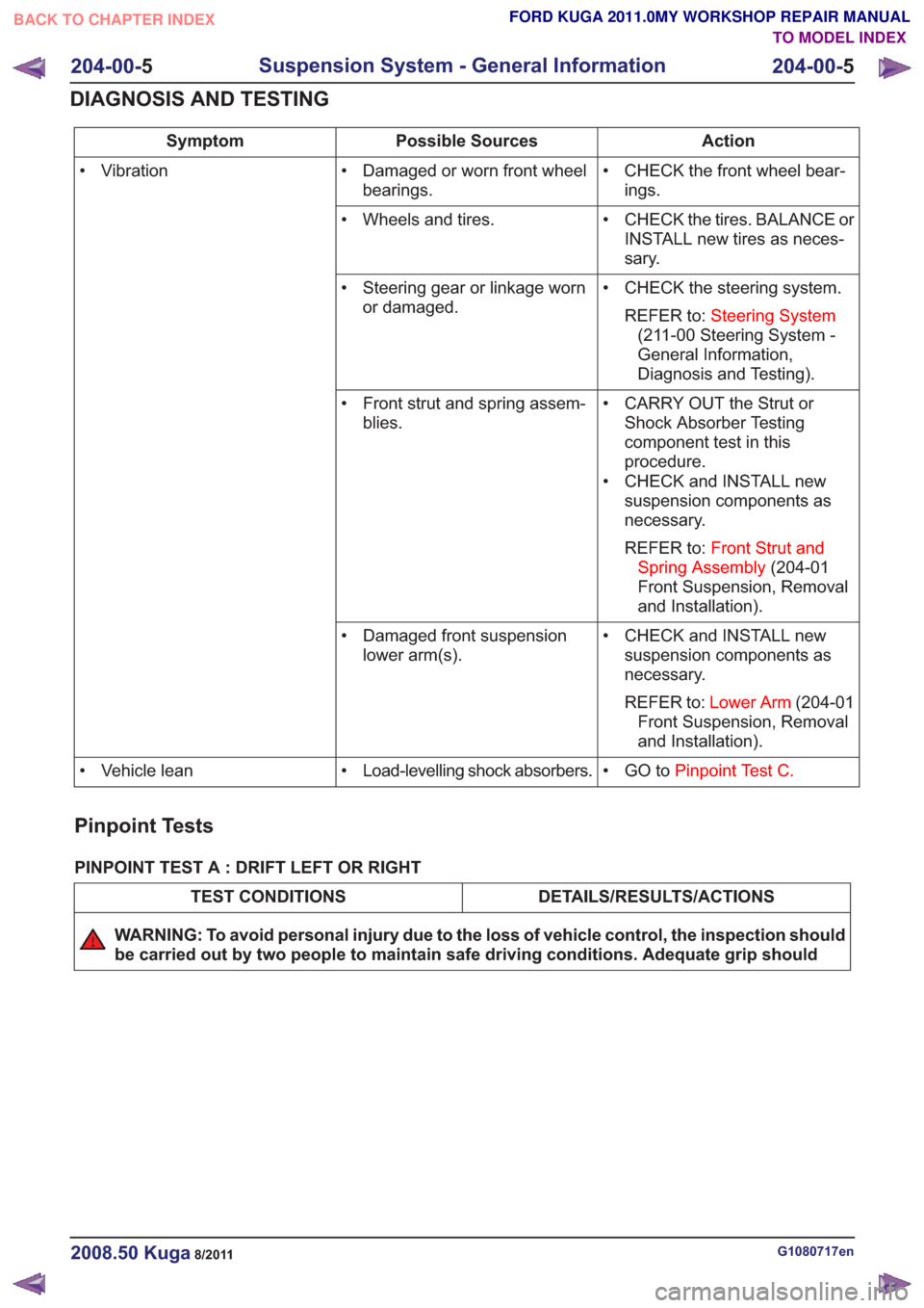
Action
Possible Sources
Symptom
• CHECK the front wheel bear-ings.
• Damaged or worn front wheel
bearings.
• Vibration
• CHECK the tires. BALANCE orINSTALL new tires as neces-
sary.
• Wheels and tires.
• CHECK the steering system.REFER to: Steering System
(211-00 Steering System -
General Information,
Diagnosis and Testing).
• Steering gear or linkage worn
or damaged.
• CARRY OUT the Strut orShock Absorber Testing
component test in this
procedure.
• CHECK and INSTALL new suspension components as
necessary.
REFER to: Front Strut and
Spring Assembly (204-01
Front Suspension, Removal
and Installation).
• Front strut and spring assem-
blies.
• CHECK and INSTALL newsuspension components as
necessary.
REFER to: Lower Arm (204-01
Front Suspension, Removal
and Installation).
• Damaged front suspension
lower arm(s).
• GO toPinpoint Test C.
• Load-levelling shock absorbers.
• Vehicle lean
Pinpoint Tests
PINPOINT TEST A : DRIFT LEFT OR RIGHT
DETAILS/RESULTS/ACTIONS
TEST CONDITIONS
WARNING: To avoid personal injury due to the loss of vehicle control, the inspection should
be carried out by two people to maintain safe driving conditions. Adequate grip should
G1080717en2008.50 Kuga8/2011
204-00- 5
Suspension System - General Information
204-00- 5
DIAGNOSIS AND TESTING
TO MODEL INDEX
BACK TO CHAPTER INDEX
FORD KUGA 2011.0MY WORKSHOP REPAIR MANUAL
Page 1161 of 2057

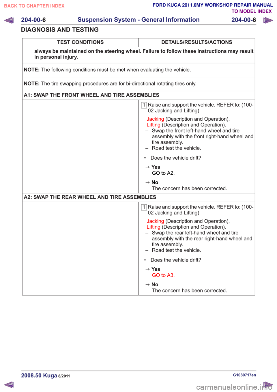
DETAILS/RESULTS/ACTIONS
TEST CONDITIONS
always be maintained on the steering wheel. Failure to follow these instructions may result
in personal injury.
NOTE: The following conditions must be met when evaluating the vehicle.
NOTE: The tire swapping procedures are for bi-directional rotating tires only.
A1: SWAP THE FRONT WHEEL AND TIRE ASSEMBLIES
1 Raise and support the vehicle. REFER to: (100-
02 Jacking and Lifting)
Jacking (Description and Operation),
Lifting (Description and Operation).
– Swap the front left-hand wheel and tire assembly with the front right-hand wheel and
tire assembly.
– Road test the vehicle.
• Does the vehicle drift?
zYe s GO to A2.
zNoThe concern has been corrected.
A2: SWAP THE REAR WHEEL AND TIRE ASSEMBLIES
1 Raise and support the vehicle. REFER to: (100-
02 Jacking and Lifting)
Jacking (Description and Operation),
Lifting (Description and Operation).
– Swap the rear left-hand wheel and tire assembly with the rear right-hand wheel and
tire assembly.
– Road test the vehicle.
• Does the vehicle drift?
zYe s GO to A3.
zNoThe concern has been corrected.
G1080717en2008.50 Kuga8/2011
204-00- 6
Suspension System - General Information
204-00- 6
DIAGNOSIS AND TESTING
TO MODEL INDEX
BACK TO CHAPTER INDEX
FORD KUGA 2011.0MY WORKSHOP REPAIR MANUAL