Page 1685 of 2057
Radiator — 2.5L Duratec (147kW/200PS) - VI5(24 254 0)
General EquipmentCable Ties
Hose Clamp Remover/Installer
Removal
NOTE: Removal steps in this procedure may
contain installation details.
1.
E112311
2.
E112335
3. Refer to: Charge Air Cooler (303-12 Intake Air
Distribution and Filtering - 2.5L Duratec
(147kW/200PS) - VI5, Removal and
Installation).
4. Refer to: Cooling System Draining and Vacuum
Filling (303-03 Engine Cooling, General
Procedures).
5. Torque: 25
Nm
E112625
x2x2
6. NOTE: The gasket is to be reused unless
damaged.
E99980
Vehicles with automatic transmission
7. General Equipment: Cable Ties
G1156381en2008.50 Kuga8/2011
303-03- 14
Engine Cooling
303-03- 14
REMOVAL AND INSTALLATION
TO MODEL INDEX
BACK TO CHAPTER INDEX
FORD KUGA 2011.0MY WORKSHOP REPAIR MANUAL
Page 1792 of 2057

• Torque reduction request (stability assistmodule)
• Cruise control request
The PCM sends the following signals via the CAN
databus:
• Fuel pump relay on/off
• Engine speed
• Warning lights on/off (MIL (malfunction indicator lamp), battery warning lamp)
• PAT S
•ECT
• Air conditioning pressure transducer
• Outside air temperature
With the aid of the input and output signals listed
above, the PCM controls / regulates engine
starting, fuel injection and fuel pressure, ignition,
boost pressure, camshaft adjustment, tank purging,
the radiator fan and the refrigerant compressor.
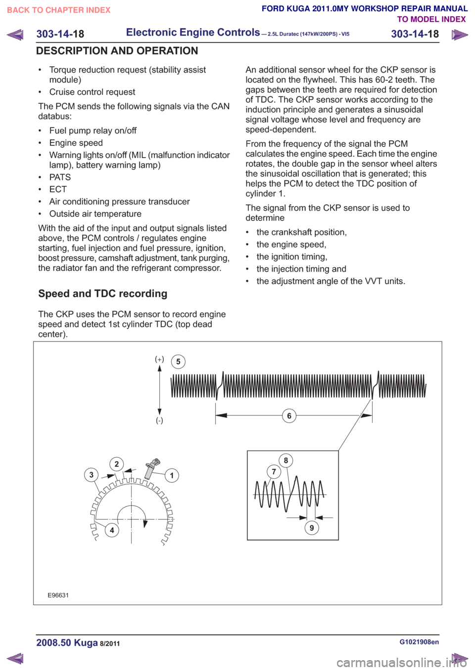
Speed and TDC recording
The CKP uses the PCM sensor to record engine
speed and detect 1st cylinder TDC (top dead
center). An additional sensor wheel for the CKP sensor is
located on the flywheel. This has 60-2 teeth. The
gaps between the teeth are required for detection
of TDC. The CKP sensor works according to the
induction principle and generates a sinusoidal
signal voltage whose level and frequency are
speed-dependent.
From the frequency of the signal the PCM
calculates the engine speed. Each time the engine
rotates, the double gap in the sensor wheel alters
the sinusoidal oscillation that is generated; this
helps the PCM to detect the TDC position of
cylinder 1.
The signal from the CKP sensor is used to
determine
• the crankshaft position,
• the engine speed,
• the ignition timing,
• the injection timing and
• the adjustment angle of the VVT units.
2
3
4
1
9
7
8
6
5
2
3
4
1
9
7
8
6
5
E96631
G1021908en2008.50 Kuga8/2011
303-14-
18
Electronic Engine Controls— 2.5L Duratec (147kW/200PS) - VI5303-14-
18
DESCRIPTION AND OPERATION
TO MODEL INDEX
BACK TO CHAPTER INDEX
FORD KUGA 2011.0MY WORKSHOP REPAIR MANUAL
Page 1805 of 2057

E74168
1
23456
Description
Item
Stop screw
1
Toothed segment
2
Throttle flap spindle
3
Throttle flap return spring
4
Joint shaft
5
Electric motor with pinion
6
CAUTION: The throttle control unit must
not be repaired or adjusted. The stop of
the throttle valve must on no account be
adjusted.
If there is a fault, the throttle is returned to its
original position by means of the throttle valve
return spring. In this position, the throttle valve is
still slightly open. As a result, a higher idle speed
is set, enabling the vehicle to be driven, though
within narrow limits.
ECT sensor
E94804
The ECT sensor is designed as an NTC resistor.
A voltage of 5V is applied to the ECT sensor by
the PCM. The PCM is able to determine the coolant
temperature from the temperature-dependent
voltage drop at the sensor.
Cooling fan module
E94806
The cooling fan module is directly supplied with
battery power via a 60A fuse in the BJB. The
radiator fan speed is controlled by the PWM via a
PCM signal.
G1021908en2008.50 Kuga8/2011
303-14- 31
Electronic Engine Controls— 2.5L Duratec (147kW/200PS) - VI5303-14-
31
DESCRIPTION AND OPERATION
TO MODEL INDEX
BACK TO CHAPTER INDEX
FORD KUGA 2011.0MY WORKSHOP REPAIR MANUAL
Page 1829 of 2057
Transaxle cooling
1
2
3
4
E112583
Description
Item
The transmission fluid cooler.
1
Quick-release couplings
2Description
Item
From transmission fluid cooler to
transmission
3
From transmission to transmission fluid
cooler
4
The transmission fluid cooler is mounted on the
radiator. The transmission fluid cooler and the
automatic transaxle are connected via two hose
lines, which are equipped with quick-release
couplings. The transmission fluid cooler operates according
to the heat exchanger principle. The ram air
passing through the radiator withdraws heat from
the transmission fluid.
External shift mechanism
G1163604en2008.50 Kuga8/2011
307-01-
8
Automatic Transmission/Transaxle
— Vehicles With:
5-Speed Automatic Transaxle - AW55 AWD
307-01- 8
DESCRIPTION AND OPERATION
TO MODEL INDEX
BACK TO CHAPTER INDEX
FORD KUGA 2011.0MY WORKSHOP REPAIR MANUAL
Page 1924 of 2057
Transmission Cooling – Overview
Overview
The transmission fluid cooler is secured on the
radiator.
The transmission fluid cooler operates according
to the heat exchanger principle. The ram air
passing through the radiator withdraws heat from
the transmission fluid.
G1163664en2008.50 Kuga8/2011
307-02-3
Transmission/Transaxle Cooling
— Vehicles With: 5-Speed
Automatic Transaxle - AW55 AWD/6-Speed Automatic Transaxle - 6DCT450
307-02- 3
DESCRIPTION AND OPERATION
TO MODEL INDEX
BACK TO CHAPTER INDEX
FORD KUGA 2011.0MY WORKSHOP REPAIR MANUAL
Page 2014 of 2057

Climate Control System
Refer to Wiring Diagrams Section 412-00, for
schematic and connector information.
Special Tool(s) / General EquipmentTerminal Probe Kit
418-S035
29011A
Digital Multimeter (compatible with K-type
thermocouple)
The Ford approved diagnostic tool
Refrigerant center
Thermometer - Fluke 80 PK-8 (FSE number 260
4102 001 07)
Inspection and Checking
NOTE:The electronic automatic temperature
control (EATC) module is integrated into the air
conditioning control assembly.
1. VERIFY customer concern.
2. Visually CHECK for any obvious mechanical or electrical damage.
NOTE: Ensure correct locking of the wiring harness
connector.
Visual Inspection
Electrical
Mechanical
• Fuses
• Wiring harness
• Connector
• Refrigerant lines
• Condenser core
• Coolant level
• Drive belt
• A/C compressor
3. RECTIFY any obvious causes for a concern found during the visual inspection before
performing any further tests. CHECK the
operation of the system.
4. If the concern is still present after the visual inspection, perform fault diagnosis on the
electronic engine management, the charging
system, the generic electronic module (GEM)
and the instrument cluster (vehicles with EATC:
read out the EATC fault memory as well) using the Ford approved diagnostic tool and RECTIFY
the fault(s) displayed in accordance with the
fault description. CHECK the operation of the
system.
5. For vehicles with no stored fault(s), PROCEED in accordance with the Symptom Chart
according to the fault symptom.
6. Following checking or elimination of the fault(s) and after completion of operations, the fault
memories of all vehicle modules must be READ
OUT and any stored faults must be DELETED.
Refrigerant Circuit - Quick Check
WARNING: The air conditioning system is
filled with refrigerant R134a. Observe
"Health and Safety Precautions". For
further information
REFER to: Air Conditioning (A/C) System
Recovery, Evacuation and Charging
(412-00 Climate Control System - General
Information, General Procedures).
Refrigerant circuit check
WARNING: Under certain circumstances,
refrigerant lines and A/C components may
be extremely hot or cold. Exercising care,
touch the refrigerant lines or A/C
components in order to check this. Failure
to follow these instructions may result in
personal injury.
When the A/C system is operating, the following
conditions should apply:
• The refrigerant line from the refrigerant compressor to the condenser must be hot.
• The refrigerant line from the A/C condenser to the fixed orifice tube must be warm, but not so
hot as the refrigerant line mentioned above.
• Determine the difference in temperature upstream and downstream of the A/C condenser
by measuring the temperatures at the refrigerant
lines. The temperature difference should be
more than 20° C, depending on the ambient
temperature. If the temperature difference is
less, check the condenser for contamination or
damage to the fins as well as operation of the
radiator fans.
G1055878en2008.50 Kuga8/2011
412-00- 3
Climate Control System - General Information
412-00- 3
DIAGNOSIS AND TESTING
TO MODEL INDEX
BACK TO CHAPTER INDEX
FORD KUGA 2011.0MY WORKSHOP REPAIR MANUAL