Page 1583 of 2057

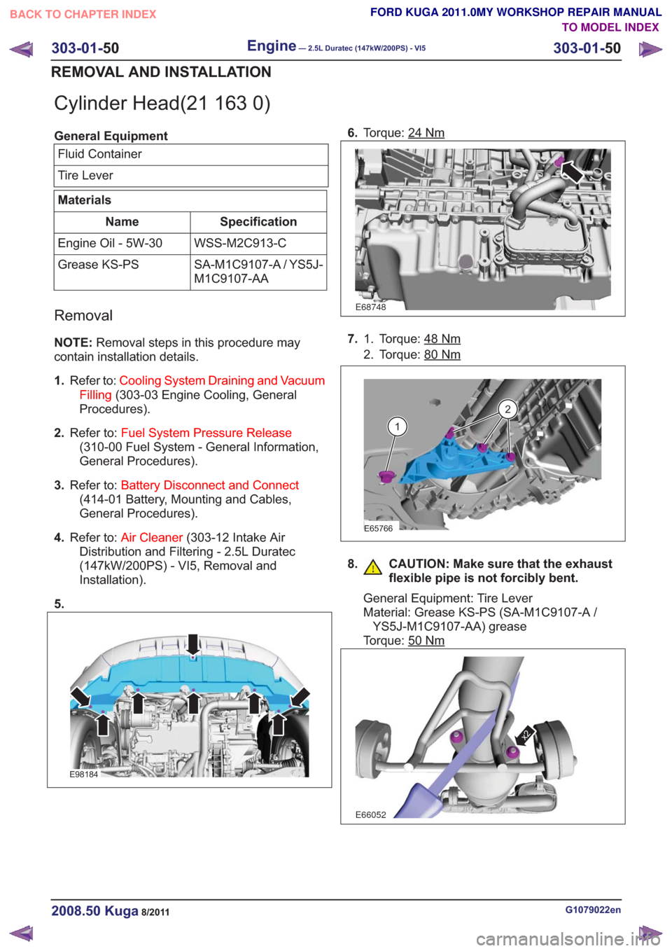
Cylinder Head(21 163 0)
General EquipmentFluid Container
Tire Lever
Materials
Specification
Name
WSS-M2C913-C
Engine Oil - 5W-30
SA-M1C9107-A / YS5J-
M1C9107-AA
Grease KS-PS
Removal
NOTE:
Removal steps in this procedure may
contain installation details.
1. Refer to: Cooling System Draining and Vacuum
Filling (303-03 Engine Cooling, General
Procedures).
2. Refer to: Fuel System Pressure Release
(310-00 Fuel System - General Information,
General Procedures).
3. Refer to: Battery Disconnect and Connect
(414-01 Battery, Mounting and Cables,
General Procedures).
4. Refer to: Air Cleaner (303-12 Intake Air
Distribution and Filtering - 2.5L Duratec
(147kW/200PS) - VI5, Removal and
Installation).
5.
E98184
6. Torque: 24Nm
E68748
7. Torque: 48Nm1.
2. Torque: 80
Nm
E65766
1
2
8. CAUTION: Make sure that the exhaust
flexible pipe is not forcibly bent.
General Equipment: Tire Lever
Material: Grease KS-PS (SA-M1C9107-A /YS5J-M1C9107-AA) grease
Torque: 50
Nm
E66052
x2
G1079022en2008.50 Kuga8/2011
303-01- 50
Engine— 2.5L Duratec (147kW/200PS) - VI5303-01-
50
REMOVAL AND INSTALLATION
TO MODEL INDEX
BACK TO CHAPTER INDEX
FORD KUGA 2011.0MY WORKSHOP REPAIR MANUAL
Page 1587 of 2057
27. CAUTION: Note the position of thecomponents before removal.
E68493
x20
x5
28. CAUTION: Make sure that no fluids arepresent in the threaded bores.
Torque:
• Stage 1: 20
Nm
• Stage 2: 60Nm
• Stage 3: 130°
E68494
1591284
37111062
29. WARNING: Be prepared to collectescaping fluid.
General Equipment: Fluid Container
Torque: 38
Nm
E115890
30.Torque: 25Nm
E115891
31.
E116077
Installation
1.To install, reverse the removal procedure.
G1079022en2008.50 Kuga8/2011
303-01- 54
Engine— 2.5L Duratec (147kW/200PS) - VI5303-01-
54
REMOVAL AND INSTALLATION
TO MODEL INDEX
BACK TO CHAPTER INDEX
FORD KUGA 2011.0MY WORKSHOP REPAIR MANUAL
Page 1588 of 2057
2. CAUTION: Make sure that fluid level isto the MAX mark.
Refer to: Specifications (303-01 Engine - 2.5L
Duratec (147kW/200PS) - VI5, Specifications).
Material: Engine Oil - 5W-30 (WSS-M2C913-C) engine oil
E116204
3. Refer to: Door Window Motor Initialization
(501-11 Glass, Frames and Mechanisms,
General Procedures).
G1079022en2008.50 Kuga8/2011
303-01- 55
Engine— 2.5L Duratec (147kW/200PS) - VI5303-01-
55
REMOVAL AND INSTALLATION
TO MODEL INDEX
BACK TO CHAPTER INDEX
FORD KUGA 2011.0MY WORKSHOP REPAIR MANUAL
Page 1591 of 2057

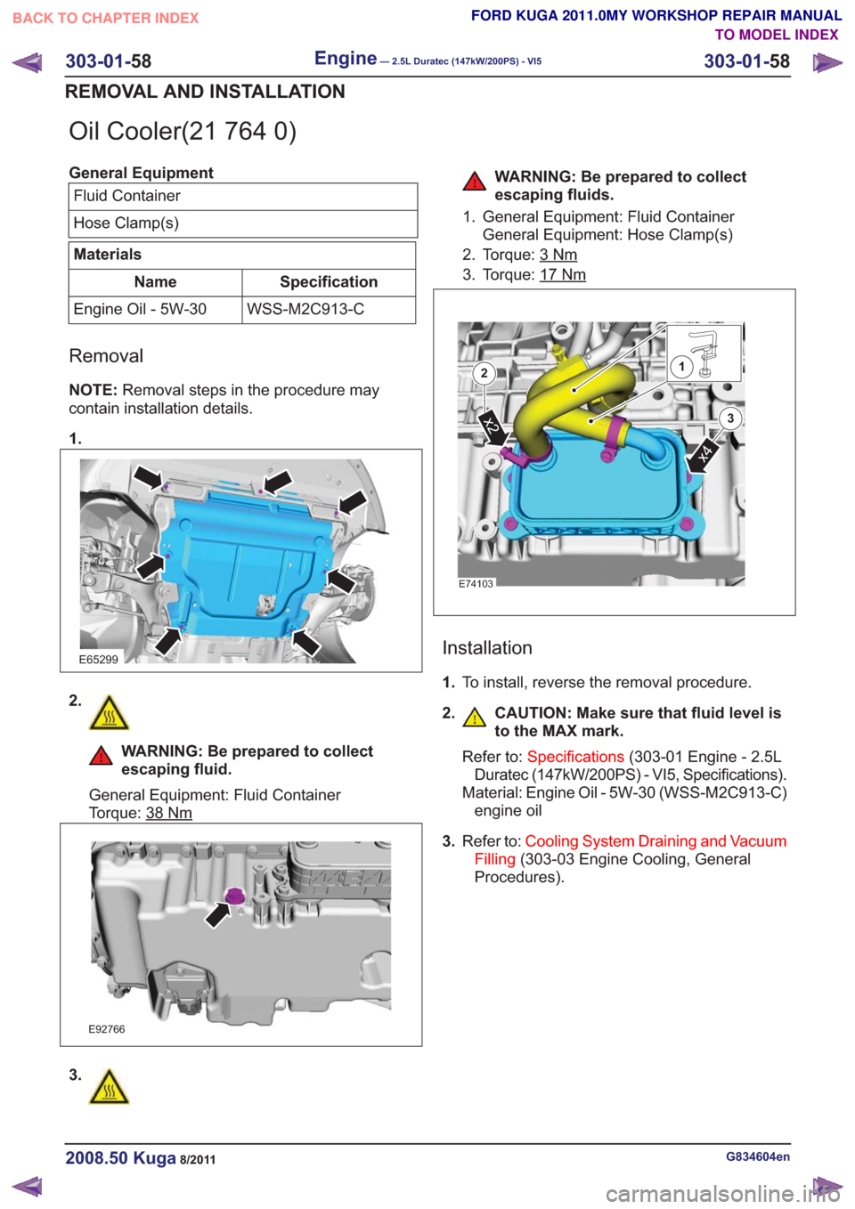
Oil Cooler(21 764 0)
General EquipmentFluid Container
Hose Clamp(s)
Materials
Specification
Name
WSS-M2C913-C
Engine Oil - 5W-30
Removal
NOTE: Removal steps in the procedure may
contain installation details.
1.
E65299
2.
WARNING: Be prepared to collect
escaping fluid.
General Equipment: Fluid Container
Torque: 38
Nm
E92766
3.
WARNING: Be prepared to collect
escaping fluids.
1. General Equipment: Fluid Container General Equipment: Hose Clamp(s)
2. Torque: 3
Nm
3. Torque: 17Nm
E74103
x4
x2
2
3
1
Installation
1. To install, reverse the removal procedure.
2. CAUTION: Make sure that fluid level is to the MAX mark.
Refer to: Specifications (303-01 Engine - 2.5L
Duratec (147kW/200PS) - VI5, Specifications).
Material: Engine Oil - 5W-30 (WSS-M2C913-C) engine oil
3. Refer to: Cooling System Draining and Vacuum
Filling (303-03 Engine Cooling, General
Procedures).
G834604en2008.50 Kuga8/2011
303-01- 58
Engine— 2.5L Duratec (147kW/200PS) - VI5303-01-
58
REMOVAL AND INSTALLATION
TO MODEL INDEX
BACK TO CHAPTER INDEX
FORD KUGA 2011.0MY WORKSHOP REPAIR MANUAL
Page 1603 of 2057
38.
E67408
39. WARNING: Be prepared to collectescaping fluid.
Refer to: Quick Release Coupling (310-00 Fuel
System - General Information, General
Procedures).
E68475
41. General Equipment: Hose Clamp
Remover/Installer
E112312
42.
E66479
G1191240en2008.50 Kuga8/2011
303-01- 70
Engine— 2.5L Duratec (147kW/200PS) - VI5303-01-
70
REMOVAL
FORD KUGA 2011.0MY WORKSHOP REPAIR MANUAL
TO MODEL INDEX
BACK TO CHAPTER INDEX
E65220
37.40.
E68429
Page 1607 of 2057
59. WARNING: Be prepared to collectescaping fluid.General Equipment: Hose Clamp
Remover/Installer
3.
E112533
1
3
x3
2
x34
x3
2
4x3
60.
E112534
1
2
61. WARNING: Be prepared to collect
escaping fluid.
General Equipment: Cable Ties
G1191240en2008.50 Kuga8/2011
303-01- 74
Engine— 2.5L Duratec (147kW/200PS) - VI5303-01-
74
REMOVAL
TO MODEL INDEX
BACK TO CHAPTER INDEX
FORD KUGA 2011.0MY WORKSHOP REPAIR MANUAL
Page 1676 of 2057

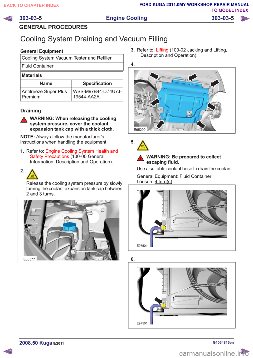
Cooling System Draining and Vacuum Filling
General EquipmentCooling System Vacuum Tester and Refiller
Fluid Container
Materials
Specification
Name
WSS-M97B44-D / 4U7J-
19544-AA2A
Antifreeze Super Plus
Premium
Draining
WARNING: When releasing the cooling
system pressure, cover the coolant
expansion tank cap with a thick cloth.
NOTE: Always follow the manufacturer's
instructions when handling the equipment.
1. Refer to: Engine Cooling System Health and
Safety Precautions (100-00 General
Information, Description and Operation).
2.
Release the cooling system pressure by slowly
turning the coolant expansion tank cap between
2 and 3 turns.
E68577
3. Refer to: Lifting(100-02 Jacking and Lifting,
Description and Operation).
4.
E65299
5.
WARNING: Be prepared to collect
escaping fluid.
Use a suitable coolant hose to drain the coolant.
General Equipment: Fluid Container
Loosen: 4
turn(s)
E97501
6.
E97501
G1034816en2008.50 Kuga8/2011
303-03- 5
Engine Cooling
303-03- 5
GENERAL PROCEDURES
TO MODEL INDEX
BACK TO CHAPTER INDEX
FORD KUGA 2011.0MY WORKSHOP REPAIR MANUAL
Page 1677 of 2057

7.
E65299
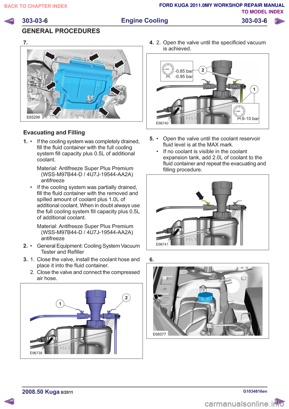
Evacuating and Filling
1.If the cooling system was completely drained,
fill the fluid container with the full cooling
•
system fill capacity plus 0.5L of additional
coolant.
Material: Antifreeze Super Plus Premium(WSS-M97B44-D / 4U7J-19544-AA2A)
antifreeze
• If the cooling system was partially drained, fill the fluid container with the removed and
spilled amount of coolant plus 1.0L of
additional coolant. When in doubt always use
the full cooling system fill capacity plus 0.5L
of additional coolant.
Material: Antifreeze Super Plus Premium(WSS-M97B44-D / 4U7J-19544-AA2A)
antifreeze
2. General Equipment: Cooling System Vacuum
Tester and Refiller
•
3. Close the valve, install the coolant hose and
place it into the fluid container.
1.
2. Close the valve and connect the compressed
air hose.
E96739
1
2
4. Open the valve until the specificied vacuum
is achieved.
2.
E967406-10 bar
1
-0.85 bar
-0.95 bar2
5.
Open the valve until the coolant reservoir
fluid level is at the MAX mark.
•
• If no coolant is visible in the coolant
expansion tank, add 2.0L of coolant to the
fluid container and repeat the evacuating and
filling procedure.
E96741
6.
E68577
G1034816en2008.50 Kuga8/2011
303-03- 6
Engine Cooling
303-03- 6
GENERAL PROCEDURES
TO MODEL INDEX
BACK TO CHAPTER INDEX
FORD KUGA 2011.0MY WORKSHOP REPAIR MANUAL