Page 1528 of 2057

TIE44583
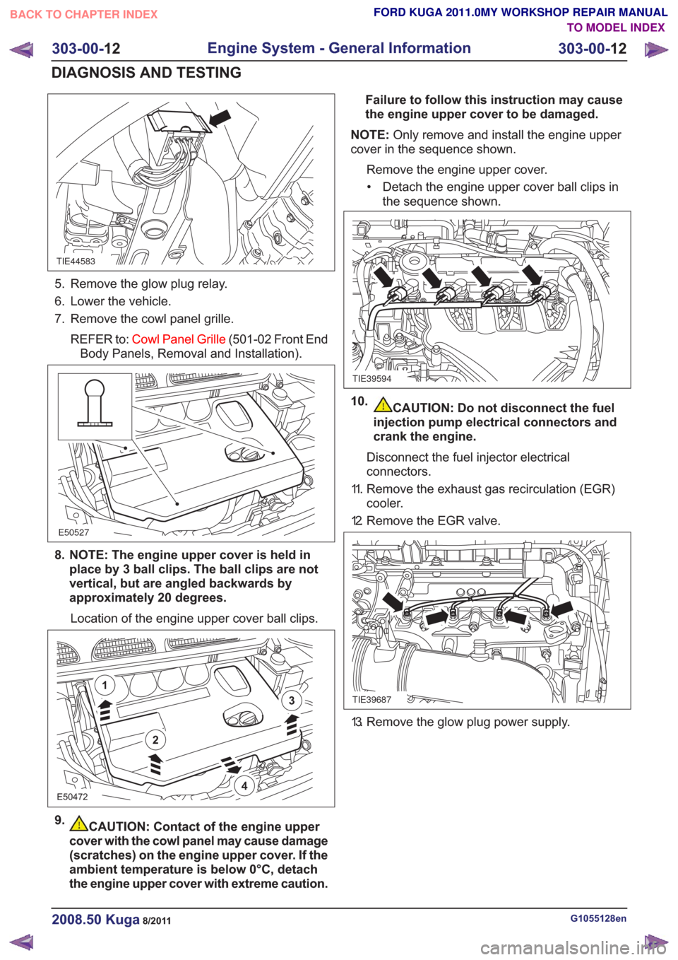
5. Remove the glow plug relay.
6. Lower the vehicle.
7. Remove the cowl panel grille.REFER to: Cowl Panel Grille (501-02 Front End
Body Panels, Removal and Installation).
E50527
8. NOTE: The engine upper cover is held in place by 3 ball clips. The ball clips are not
vertical, but are angled backwards by
approximately 20 degrees.
Location of the engine upper cover ball clips.
E50472
2
1
3
4
9.CAUTION: Contact of the engine upper
cover with the cowl panel may cause damage
(scratches) on the engine upper cover. If the
ambient temperature is below 0°C, detach
the engine upper cover with extreme caution. Failure to follow this instruction may cause
the engine upper cover to be damaged.
NOTE: Only remove and install the engine upper
cover in the sequence shown.
Remove the engine upper cover.• Detach the engine upper cover ball clips in the sequence shown.
TIE39594
10.CAUTION: Do not disconnect the fuel
injection pump electrical connectors and
crank the engine.
Disconnect the fuel injector electrical
connectors.
11. Remove the exhaust gas recirculation (EGR) cooler.
12. Remove the EGR valve.
TIE39687
13. Remove the glow plug power supply.
G1055128en2008.50 Kuga8/2011
303-00- 12
Engine System - General Information
303-00- 12
DIAGNOSIS AND TESTING
TO MODEL INDEX
BACK TO CHAPTER INDEX
FORD KUGA 2011.0MY WORKSHOP REPAIR MANUAL
Page 1529 of 2057

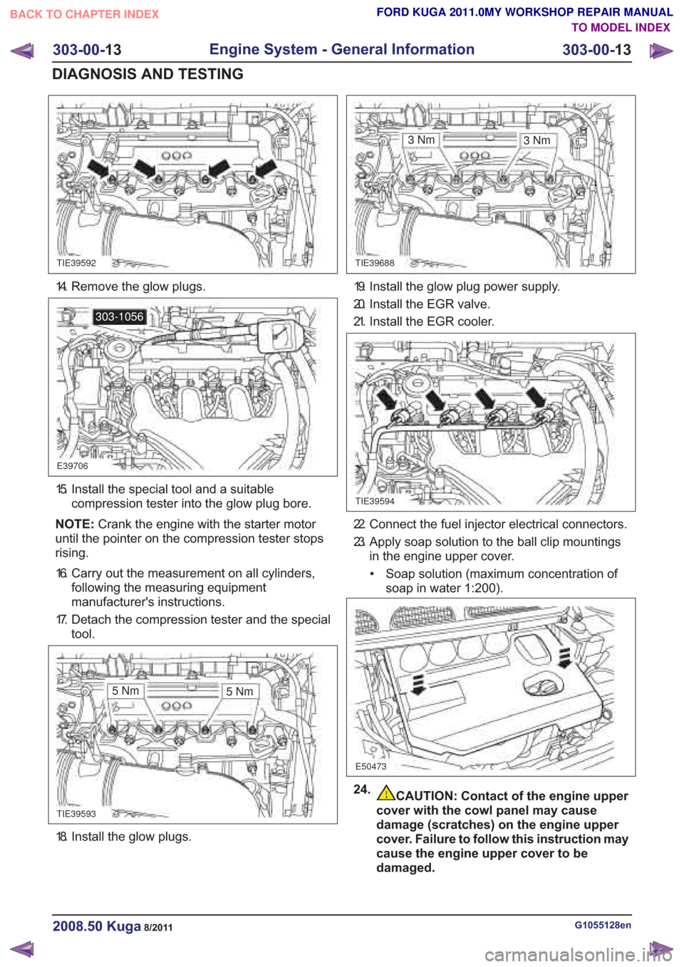
18. Install the glow plugs.
CAUTION: Contact of the engine upper
cover with the cowl panel may cause
damage (scratches) on the engine upper
cover. Failure to follow this instruction may
cause the engine upper cover to be
damaged.
G1055128en2008.50 Kuga8/2011
303-00- 13
Engine System - General Information
303-00- 13
DIAGNOSIS AND TESTING
FORD KUGA 2011.0MY WORKSHOP REPAIR MANUAL
TO MODEL INDEX
BACK TO CHAPTER INDEX
TIE39592TIE39688
E39706
303-1056
TIE39593
3Nm
TIE39594
E50473
3Nm
5Nm 5Nm
14. Remove the glow plugs.
15. Install the special tool and a suitable
compression tester into the glow plug bore.
NOTE: Crank the engine with the starter motor
until the pointer on the compression tester stops
rising.
16. Carry out the measurement on all cylinders, following the measuring equipment
manufacturer's instructions.
17. Detach the compression tester and the special tool.
19. Install the glow plug power supply.
20. Install the EGR valve.
21. Install the EGR cooler.
22. Connect the fuel injector electrical connectors.
23. Apply soap solution to the ball clip mountingsin the engine upper cover.
• Soap solution (maximum concentration of soap in water 1:200).
24.
Page 1675 of 2057

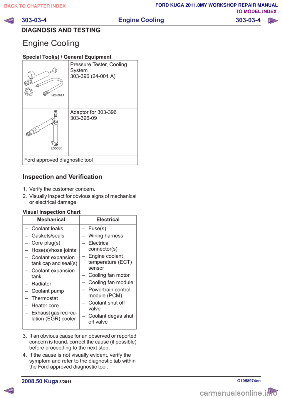
Engine Cooling
Special Tool(s) / General EquipmentPressure Tester, Cooling
System
303-396 (24-001 A)
IA24001A
Adaptor for 303-396
303-396-09
E55030
Ford approved diagnostic tool
Inspection and Verification
1. Verify the customer concern.
2. Visually inspect for obvious signs of mechanicalor electrical damage.
Visual Inspection Chart
Electrical
Mechanical
– Fuse(s)
– Wiring harness
– Electricalconnector(s)
– Engine coolant temperature (ECT)
sensor
– Cooling fan motor
– Cooling fan module
– Powertrain control module (PCM)
– Coolant shut off valve
– Coolant degas shut off valve
– Coolant leaks
– Gaskets/seals
– Core plug(s)
– Hose(s)/hose joints
– Coolant expansion
tank cap and seal(s)
– Coolant expansion tank
– Radiator
– Coolant pump
– Thermostat
– Heater core
– Exhaust gas recircu- lation (EGR) cooler
3. If an obvious cause for an observed or reported concern is found, correct the cause (if possible)
before proceeding to the next step.
4. If the cause is not visually evident, verify the symptom and refer to the diagnostic tab within
the Ford approved diagnostic tool.
G1058974en2008.50 Kuga8/2011
303-03- 4
Engine Cooling
303-03- 4
DIAGNOSIS AND TESTING
TO MODEL INDEX
BACK TO CHAPTER INDEX
FORD KUGA 2011.0MY WORKSHOP REPAIR MANUAL
Page 1802 of 2057

voltage signal to the PCM corresponding to the
aspirated air mass.
This analogue voltage signal is between 0.5V and
5V. Low mass of intake air produces a low voltage
signal. A high mass of intake air produces a
correspondingly high voltage signal.
The MAF sensor is also capable of detecting the
backflow of the intake air. A sensor element is
heated electrically on the integrated chip and then
cooled by the air flowing through. The regulating
switch supplies the heating current in such a way
that it attains a constant excess temperature in
comparison to the intake air. The mass air flow and
the direction of flow can be derived from this
heating current (given in the form of a signal
voltage). Below a certain voltage value there is a
return flow. The direction is flow is registered by
two sensors pointing in different directions. The
measurement does not require a great deal of
software processing effort, even with a strongly
pulsating mass air flow.MAPT
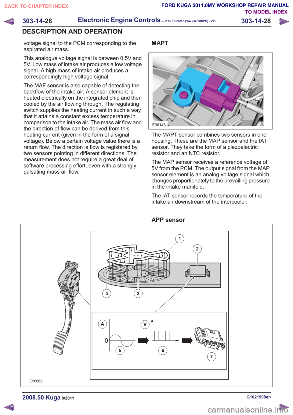
E96146
The MAPT sensor combines two sensors in one
housing. These are the MAP sensor and the IAT
sensor. They take the form of a piezoelectric
resistor and an NTC resistor.
The MAP sensor receives a reference voltage of
5V from the PCM. The output signal from the MAP
sensor element is an analog voltage signal which
changes proportionately to the prevailing pressure
in the intake manifold.
The IAT sensor records the temperature of the
intake air downstream of the intercooler.
APP sensor
00
E96668
1
2
43
AV
56
7
G1021908en2008.50 Kuga8/2011
303-14-28
Electronic Engine Controls— 2.5L Duratec (147kW/200PS) - VI5303-14-
28
DESCRIPTION AND OPERATION
TO MODEL INDEX
BACK TO CHAPTER INDEX
FORD KUGA 2011.0MY WORKSHOP REPAIR MANUAL