Page 1491 of 2057
Vehicles with 2.5L engine
11 .
E141077
12.
E141078
13. N O T E :Make sure the fluid in the reservoir does
not fall below the MIN mark, as air could enter
the system.
Slowly turn the steering wheel from lock to lock
five times.
E131522
123
14.
E141079
12
15.
E141077
G1001271en2008.50 Kuga8/2011
211-02- 34
Power Steering
211-02- 34
REMOVAL AND INSTALLATION
TO MODEL INDEX
BACK TO CHAPTER INDEX
FORD KUGA 2011.0MY WORKSHOP REPAIR MANUAL
Page 1493 of 2057
Steering Gear to Power Steering Fluid Reservoir Return Line —2.5L Duratec (147kW/200PS) - VI5(13 439 0)
General Equipment
Hose Clamp Remover/Installer
Removal
NOTE: Removal steps in this procedure may
contain installation details.
1. Refer to: Steering System Health and Safety
Precautions (100-00 General Information,
Description and Operation).
2. Refer to: Wheel and Tire (204-04 Wheels and
Tires, Removal and Installation).
3.
E98543
x7
4.
E99630
5.
E99631
6. WARNING: Be prepared to collect escaping fluid.
1. General Equipment: Hose ClampRemover/Installer
2. Torque: 30
Nm
E114706
1
2
7. Torque: 23Nm1.
2. Torque: 7
Nm
G1185536en2008.50 Kuga8/2011
211-02- 36
Power Steering
211-02- 36
REMOVAL AND INSTALLATION
TO MODEL INDEX
BACK TO CHAPTER INDEX
FORD KUGA 2011.0MY WORKSHOP REPAIR MANUAL
Page 1494 of 2057
E112634
2
1
8.Torque: 4Nm
E99258
9. WARNING: Be prepared to collect
escaping fluid.
CAUTION: Make sure that all openings
are sealed.
Torque: 18
Nm
E114705
10.
G1185536en2008.50 Kuga8/2011
211-02- 37
Power Steering
211-02- 37
REMOVAL AND INSTALLATION
TO MODEL INDEX
BACK TO CHAPTER INDEX
FORD KUGA 2011.0MY WORKSHOP REPAIR MANUAL
Page 1496 of 2057
Installation
1.To install, reverse the removal procedure.
2.
E141077
3.
E141078
4. NOTE: Make sure the fluid in the reservoir does
not fall below the MIN mark, as air could enter
the system.
Slowly turn the steering wheel from lock to lock
five times.
E131522
123
5.
E141079
12
6.
E141077
G1185536en2008.50 Kuga8/2011
211-02- 39
Power Steering
211-02- 39
REMOVAL AND INSTALLATION
TO MODEL INDEX
BACK TO CHAPTER INDEX
FORD KUGA 2011.0MY WORKSHOP REPAIR MANUAL
Page 1525 of 2057

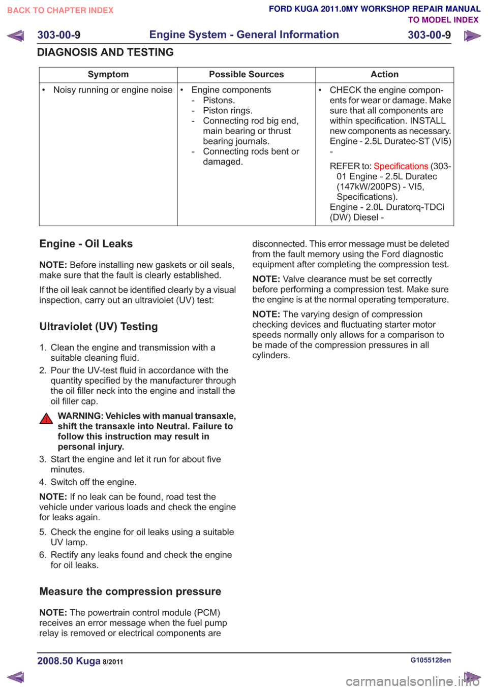
Action
Possible Sources
Symptom
• CHECK the engine compon-ents for wear or damage. Make
sure that all components are
within specification. INSTALL
new components as necessary.
Engine - 2.5L Duratec-ST (VI5)
-
REFER to: Specifications (303-
01 Engine - 2.5L Duratec
(147kW/200PS) - VI5,
Specifications).
Engine - 2.0L Duratorq-TDCi
(DW) Diesel -
• Engine components
- Pistons.
- Piston rings.
- Connecting rod big end,main bearing or thrust
bearing journals.
- Connecting rods bent or damaged.
• Noisy running or engine noise
Engine - Oil Leaks
NOTE:
Before installing new gaskets or oil seals,
make sure that the fault is clearly established.
If the oil leak cannot be identified clearly by a visual
inspection, carry out an ultraviolet (UV) test:
Ultraviolet (UV) Testing
1. Clean the engine and transmission with a suitable cleaning fluid.
2. Pour the UV-test fluid in accordance with the quantity specified by the manufacturer through
the oil filler neck into the engine and install the
oil filler cap.
WARNING: Vehicles with manual transaxle,
shift the transaxle into Neutral. Failure to
follow this instruction may result in
personal injury.
3. Start the engine and let it run for about five minutes.
4. Switch off the engine.
NOTE: If no leak can be found, road test the
vehicle under various loads and check the engine
for leaks again.
5. Check the engine for oil leaks using a suitable UV lamp.
6. Rectify any leaks found and check the engine for oil leaks.
Measure the compression pressure
NOTE: The powertrain control module (PCM)
receives an error message when the fuel pump
relay is removed or electrical components are disconnected. This error message must be deleted
from the fault memory using the Ford diagnostic
equipment after completing the compression test.
NOTE:
Valve clearance must be set correctly
before performing a compression test. Make sure
the engine is at the normal operating temperature.
NOTE: The varying design of compression
checking devices and fluctuating starter motor
speeds normally only allows for a comparison to
be made of the compression pressures in all
cylinders.
G1055128en2008.50 Kuga8/2011
303-00- 9
Engine System - General Information
303-00- 9
DIAGNOSIS AND TESTING
TO MODEL INDEX
BACK TO CHAPTER INDEX
FORD KUGA 2011.0MY WORKSHOP REPAIR MANUAL
Page 1544 of 2057
E62857
1
2
3
6
5
4
Description
Item
Camshaft bearings
1
Valve cover
2
Cylinder head
3Description
Item
Spark plug well sealing ring
4
Exhaust camshaft
5
intake camshaft
6
A conventional cylinder head gasket is installed
between the cylinder head and the cylinder block. The gaskets between the other mating faces are
fluid gaskets.
G1092773en2008.50 Kuga8/2011
303-01-
11
Engine— 2.5L Duratec (147kW/200PS) - VI5303-01-
11
DESCRIPTION AND OPERATION
TO MODEL INDEX
BACK TO CHAPTER INDEX
FORD KUGA 2011.0MY WORKSHOP REPAIR MANUAL
Page 1579 of 2057
WARNING: Be prepared to collect
escaping fluid.
Torque: 38
E65223
4. Torque: 17Nm
E65764
5.Torque: 48Nm
E65218
6.Torque: 48Nm
E65219
7.Torque: 10Nm
E65220
8.Torque: 17Nm
E65221
x4
303-01- 46
Engine— 2.5L Duratec (147kW/200PS) - VI5303-01-
46
REMOVAL AND INSTALLATION
TO MODEL INDEX
BACK TO CHAPTER INDEX
FORD KUGA 2011.0MY WORKSHOP REPAIR MANUAL
Nm
G543325en2008.50 Kuga8/2011
Page 1580 of 2057
9.Torque: 17Nm
E65222
Installation
1. NOTE: The component must be installed within
5 minutes of applying the sealant.
Material: Flange Sealant - Anaerobic LP (WSK-M2G348-A7 / 5U7J-M2G348-BA)
sealant
E84444
2. To install, reverse the removal procedure.
3.
CAUTION: The fluid level must remain
between the MAX and MIN marks.
Material: Engine Oil - 5W-30 (WSS-M2C913-C) engine oil
G543325en2008.50 Kuga8/2011
303-01- 47
Engine— 2.5L Duratec (147kW/200PS) - VI5303-01-
47
REMOVAL AND INSTALLATION
TO MODEL INDEX
BACK TO CHAPTER INDEX
FORD KUGA 2011.0MY WORKSHOP REPAIR MANUAL