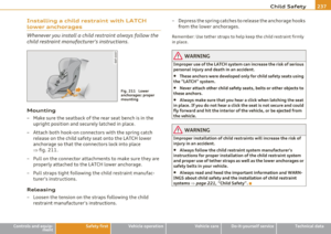
Page 329 of 364
_____________________________________________ W __ h_a_ t_ d_o_ I_ d_o _ n_ o_ w _ ? __ lffll
& WARNING (continued)
maneuver they could fly forward, causing injury to passengers in
the vehicle. •
Safety first Vehicle care Do-it-yourself service Technical data
Page 330 of 364

.,.,___F_ u_ s_e _ s_ a_n_ d_ b_u _ l_ b_ s _______________________________________________ _
Fuses and bulbs
Electrical fuses
Replacing fuses
Fuses that have blown will have metal strips that have
burned through .
Fig. 24 4 Left cockp it:
f use panel cove r
The fuses are located at the front left and right of the cockp it
and behind the trim on the righ t side of the luggage compart
ment .
- Turn off the ignition and the affected electrical
consumers.
- Check the following table to see which fuse belongs to the
consumer.
- Remove the appropriate cover.
- To remove the purple plastic clip if necessary
4>, hold onto
it at the small s ide and pull it out of the fuse panel
=--page 329, fig . 245.
4
) Yo u ca n dis p ose of the p las tic cli p afte r remo vin g it.
- Remove the clamp from the rear side of the fuse cover
=> fig. 244.
-Remove the fuse using the clamp and replace the blown
fuse with an identical new one .
& WARNING
Do not re pair fu se s a nd neve r replace a blo wn fuse with one t hat
ha s a hig her amp rating . Th is c an ca use d am ag e to t he elec tric a l
sys tem and a fire.
0 Note
If a n ew fus e burns out again after shortly have you hav e installed it,
have the electrica l system checked by your authorized Audi dealer.
[I) Tips
• The fo llow ing tab le does not list fuse locat ions that are not used .
• Some of the equipment items listed are optional o r only ava ilable
on certain model configurat ions .•
Page 331 of 364

__________________________________________ __!F~U!_.:!S~e:.:s~ a~n~d:!_..!:b~u:!!l~b~s~ _J
Left cockpit fuse assignment
No. C onsumer
Fus e pa nel @ (black )
1 Dynamic steering
3 Homelink
4 Lane Assist
5 Climate control Right headlight range adjustment
7 Left headlight range adjustment
Fig. 2 4 5 Left cock pit :
fuse pan el with plastic
cl ip
5
5
10 5
5
5
8 Vehicle electrical system control module 1 5
Vehicle OP-eration
No. Consumer Amps
9 Adaptive Cruise Control
5
10 Shift gate 5
1 1 Heater washer fluid nozzles
5
12 Climate control 5
13 Ce lt phone prep
s
14 Airbag
5
15 Term
inal 15
25
16 Terminal 15 engine 40
Fus e pa nel ® (brow n)
1 Automatic dimming interior rearview mirror 5
3 Gasoline fuel p ump 25
4 Auxiliary water pump 3 .2L FSI 5
5 Left seat heating with/wi tho ut seat heat ing 15/30
6 Electronic Stabilization Program
10
7 Horn 25
8 Left door window regulator motor 30
9 Wiper motor 30
10 Electronic Stabilization Program
25
11 Driver side door control modu le 15
12 Rain and light sensor 5
Fuse panel © (red)
3 Lumbar support 10
4 Dynamic steer
ing
35
6 Vehicle electrical system control module 1 35
7 Veh icle elect rical system control module 1 20
Vehicle care Do-it-yourself service iTechnical data
Page 332 of 364
-L__..!:F~U:!_:S~e~s~a~n~d~b~u~l!;b~s ~-------------------------------------------
No. Consumer Amps
8 II vehicle electrical system control modu le 1 30
-
9 L eft rea r window regula to r moto r 7
,5
10 Vehicle electrical system control module 1 30
11 R
ight rear window regulator motor 7,5
1 2 C onvenience electron ic s 5
Right cockpit fuse assignment
Fig. 246 Right coc kp it :
fuse panel with pla sti c
clip
•
No. Consumer Amps
Fuse panel @ (black)
5 Steer ing column switch module 5
6 Electronic Stabilization Program
5
7 Terminal 15 diagnostic connector 5
8 Gateway (Databus diagnostic interface)
5
Fuse panel
® (brown)
1 CD-/DV D player 5
2 Aud
i drive se lect switch module
s
3 MMI/Radio 5/20
4 Instrument clust er s
5 Gateway (instrument cluster control module) s
6 Ignition lock 5
7 Rotary light switch s
8 Climate control system blower 40
9 Steer ing colum n lock
5
10 Climate cont rol 10
11 Terminal 30 diagnostic connector
10
1 2 Steering column sw itch module 5
•
Page 333 of 364

Fuses and bulbs Ill ___________________ ...:......:.;...:...,:_.;__...;___--
Right luggage comp artment fuse
assignment
Fig. 2 47 R igh t luggage compartment: fuse panel wit h plastic cl ip
N o. Con sum er
Fu se pane l@ (bl ac k)
1 Power top control module
2 T railer control module
3 Trailer control module
4 Trailer control module
Electromechanical parking brake
Electronic damping control
7 Electromechanical parking brake
8 Veh icle elect rical system contro l mod ule 2 10
15
20
20
5
15
30
30
Vehicle
OP-eration
No. Consume r
9 quattro Sport
10 Veh icle electrical sys tem control modu le 2
11 Vehicle electrical system control module
12 Terminal 30
Fuse p anel © (brown)
1 Luggage compartment lid control module, vehi
cle electr ica l system control module
2 Right front seat heating
3
4
6
7
DCDC converter path 1
DCDC converter path 2
Right upper cab in heat ing
Electromechanical parking brake
8 Rear seat heating
9 Passenger side door control module
10 Left upper cabin heating
11 Passenger side door control module
F us e pa nel ® (red)
1 Rear center console outlet
2 Front center console outlet
3 Luggage compartment outlet
4 Cigarette lighter 6 Rear Seat Entertainment supply
7 Parking system
9 Electromechanical parking brake switch
10 Aud i side assist
Vehicle care Do-it-yourself service
Amps
35
30
20
5
30
15
40
40
30
30
30
30 30
15
15 15
15
15
5
7,5
5
5
iTechnical data
Page 334 of 364

-Fuses and bulbs Pf":I..._ ______________ _
No. Consumer
11 Rear seat hea ting
1 2 T ermin al 15 con trol modules
Fuse panel © (black)
3 D SP am plifi er, radio
4 MMI
5 Radio/navigation/cell phone prep
6 Rearvie w camer a
7 cell phone p rep
Bulbs
Replacing bulbs
Amps
5
5
30
7,5
5
5
5
F or your safety, we recomm end that you have your autho
riz ed Audi dealer replace any bulbs for you .
It is becoming increasing ly mo re and more d ifficult to replace vehicle
light bulbs since in many cases, other parts of the car must f irst be
removed before yo u are ab le to get to the bu lb. This app lies especially
to the light bulbs in the front of your car which you can only reac h
t hrough the eng ine comp artment.
Sheet metal and bu lb holders can have sharp edges that can cause
serious c uts, parts must be correctly taken apart and then properly
put back together to he lp prevent breakage of parts and long term
damage from water t hat can enter housings that have not been prop
erly resea led.
For your safety, we recommend that you have your authorized Audi
dealer replace a ny bu lbs for yo u, since yo ur dealer has the proper
too ls, t he cor rect bu lbs and the expertise.
Gas discharge lamps (Xenon lights)*:
•
Due to the high electrical voltage, have the bulbs replaced by a qua l
ified techn ici an . Hea dligh ts w ith Xenon light are i dent ified by t he
hig h voltage sticker.
& WARNING
Changing Xenon lamps without the necessa ry equipment can
c aus e seriou s personal injury.
• Bulbs are pressurized and can e xplode when being changed.
Potential risk of injury!
• On veh icle s equipped with gas discharge bulbs (Xenon light)*
life-threatening injuries can result from improper handling of the
high- voltage portions of such lamps!
• Only your authorized Audi dealer or a qualified workshop
should change the bulbs in gas discharge lamps. There are parts
with sharp edges on th e openings and on the bulb holder s that can
cause serious cuts. If you are uncertain about what to do , have the
work performed by an authorized Audi dealer or other qualified
workshop . Serious personal injury m ay result from improperly
performed work.
[ i ] Tips
• If yo u still p refer to rep lace the l igh t bul bs yourself, be aw are t hat
the engine compartment is a hazardous area to work in~
page 272,
"En gine compartment" ~& .
• It is best to ask your authorized Audi dealer whenever you want to
c h ange a bulb. •
Page 335 of 364

Emergency situations --------------=----Efffll
Emergency situations
General
This chapter is intended for trained emergency crew s and working
personnel who ha ve the necessar y tools and equipment to perform
the se operations . •
Starting by pushing or towing
(D Note
Vehicles with an automatic transmis sion cannot be started by
pushing or towing .•
Starting with jumper cables
If necess ary, the engine can be started by connecting it to
the battery of an other vehicle .
If the engine shou ld fai l to start because of a discharged or weak
battery, t he battery can be co nnecte d to the battery of
another
vehicle, using a pair of jumper cable s to start the engine .
Jumper cables
Use only jumper cables of suffic ient ly large cross section to carry the
sta rter cur ren t safely . Refe r to the manufacture r's specifications.
Use on ly j umper cab les with
insulated te rm ina l clamps w hich are
distinct ly marked :
plus(+) cable in most cases colo red red
minus (-) cable i n most cases colored black.
Safety first
& WARNING
Batterie s contain electricity, acid, and gas . Any of these can cause
very serious or fatal injury . Follow the inst ructions below for safe
handling of your vehicle 's battery .
• Always shield your eyes and avoid leaning over the battery
whenever possible.
• A discharged battery can freeze at temperatures just below
32 °F (0 °C). Before connecting a jumper cable, you must thaw the
frozen battery completely , otherwise it could explode.
• Do not allow battery acid to contact eyes or skin . Flush any
contacted area with water immediately .
• Improper use of a booster battery to start a vehicle may cause
an e xplosion.
• Vehicle batteries generate e xplos ive gases. Keep spa rks, flame
and lighted cigarettes away from batteries.
• Do not try to jump start any vehicle with a low acid level in the
battery.
• The voltage of the booster battery must also h ave a 12 -Volt
rating. The capacity (Ah) of the booster battery should not be
lower than that of the discharged battery. Use of batter ies of
different voltage or sub stantially different "Ah " rating may cau se
an explosion and personal injury.
• Never charge a frozen battery . Ga s trapped in the ice may cause
an e xplosion.
• Never charge or use a battery that has been frozen. The battery
case may have be weakened.
• Use of batteries of different voltage or substantially different
capacity (Ah ) rating may cause an explosion and injury . The
capacity (Ah ) of the booster battery should not be lower than that
of the discharged battery. _..
Vehicle care Do-it-yourself service Technical data
Page 336 of 364

,..,___E_ m_ e_r -=g :.. e_ n_c -=y '-- s_i_t _u _a _ t_ i_ o _ n_ s ____________________________________________ _
& WARN ING (con tin ue d)
• Before you che ck anything in the engine compartment, always
read and heed all WARNINGS~
page 272, "Engine compart
ment ".
0 Note
• App lying a higher vo ltage booster battery will cause expens ive
damage t o sens it ive e lec tron ic compone nts, such as contro l units,
re lays, rad io, etc.
• The re must be no elect rical contact between the veh icles as othe r
w ise current could already start to flow as soon as the pos it ive( +)
t erminals a re connected.
[ i ] Tips
Th e d ischarged ba ttery mus t be p roper ly connec ted to t he veh icle's
electrical system. When jump starting or charging the battery , never
conne ct the negative grou nd ca ble to the ba ttery negative post
because the battery manager system must be ab le to detect the
ba ttery's state of charge. A lways connec t the negat ive g round cable
to the negative ground post of t he battery manager cont rol un it .•
Use of jumper cables
fvf ake sure t o con nect the j umpe r ca ble clam ps i n ex a ctly
the order describ ed belo w!
Fig. 248 Engine
comp artment : Co nnec
t o rs f or jump er cabl es
a nd c harger
Fig . 249 Jump
sta rtin g with the
b at tery of another
ve hicle :@ disc harge d
v ehicle battery ,©
bo oste r battery
The procedure descri bed below for con nec ting ju mper cables
is i nten ded to prov ide a jump start for your veh icle .
Vehicle with discharged battery:
-Turn off lights and accesso ries, move l ever of au to m atic
tra nsmi ssio n to
N (Ne utr al) or P (Park) an d se t parking
bra ke .
~