Page 65 of 108

PERIODIC MAINTENANCE AND ADJUSTMENT
6-14
6 11. Install the fuel tank breather/over-
flow hoses into the guides, then
place them in their original posi-
tion.
12. Install the shift arm by aligning the
match mark on the shift arm with
the match mark on the shift shaft
and installing the bolt, then tighten-
ing it to the specified torque.
NOTICE: Be sure to align the
match marks to ensure proper
shifting. If the match marks are
not aligned, the shift arm willnot move correctly and you may
not be able to shift up or down.
[ECA15342]
13. Install the engine oil drain bolt and
its new gasket, and then tighten
the bolt to the specified torque.14. Refill with the specified amount of
the recommended engine oil, and
then install and tighten the oil filler
cap.
TIPBe sure to wipe off spilled oil on any
parts after the engine and exhaust sys-
tem have cooled down.NOTICE
ECA11620
�
In order to prevent clutch slip-
page (since the engine oil also
lubricates the clutch), do not
mix any chemical additives. Do
not use oils with a diesel speci-
fication of “CD” or oils of a high-
er quality than specified. In
1. Torque wrenchTightening torque:
Oil filter cartridge:
17 Nm (1.7 m·kgf, 12 ft·lbf)
1. Bolt
2. Shift shaft
3. Match marks
4. Shift arm
Tightening torque:
Shift arm bolt:
10 Nm (1.0 m·kgf, 7.2 ft·lbf)
Tightening torque:
Engine oil drain bolt:
43 Nm (4.3 m·kgf, 31 ft·lbf)
Recommended engine oil:
See page 8-1.
Oil quantity:
Without oil filter cartridge replace-
ment:
2.40 L (2.54 US qt, 2.11 Imp.qt)
With oil filter cartridge replacement:
2.60 L (2.75 US qt, 2.29 Imp.qt)
U13SE2E0.book Page 14 Tuesday, August 4, 2009 4:01 PM
Page 66 of 108

PERIODIC MAINTENANCE AND ADJUSTMENT
6-15
6addition, do not use oils labeled
“ENERGY CONSERVING II” or
higher.
�
Make sure that no foreign mate-
rial enters the crankcase.
15. Start the engine, and then let it idle
for several minutes while checking
it for oil leakage. If oil is leaking, im-
mediately turn the engine off and
check for the cause.TIPAfter the engine is started, the engine
oil level warning light should go off if the
oil level is sufficient.NOTICE
ECA10401
If the oil level warning light flickers
or remains on even if the oil level is
correct, immediately turn the engine
off and have a Yamaha dealer check
the vehicle.16. Turn the engine off, and then
check the oil level and correct it if
necessary.
17. Install the cowling.
EAU20070
Coolant The coolant level should be checked
before each ride. In addition, the cool-
ant must be changed at the intervals
specified in the periodic maintenance
and lubrication chart.
EAU39087
To check the coolant level
1. Place the vehicle on a level sur-
face and hold it in an upright posi-
tion.TIP�
The coolant level must be checked
on a cold engine since the level
varies with engine temperature.
�
Make sure that the vehicle is posi-
tioned straight up when checking
the coolant level. A slight tilt to the
side can result in a false reading.
2. Check the coolant level in the cool-
ant reservoir.TIPThe coolant should be between the
minimum and maximum level marks.
3. If the coolant is at or below the
minimum level mark, remove pan-
el B to access the coolant reser-
voir. (See page 6-7.)
4. Remove the coolant reservoir cap,
add coolant to the maximum level
mark, and then install the reservoir
cap. WARNING! Remove only
the coolant reservoir cap. Never
attempt to remove the radiator
cap when the engine is hot.
[EWA15161]
NOTICE: If coolant is not
available, use distilled water or
soft tap water instead. Do not
use hard water or salt water
since it is harmful to the engine.
1. Coolant reservoir
2. Maximum level mark
3. Minimum level mark
U13SE2E0.book Page 15 Tuesday, August 4, 2009 4:01 PM
Page 67 of 108

PERIODIC MAINTENANCE AND ADJUSTMENT
6-16
6 If water has been used instead
of coolant, replace it with cool-
ant as soon as possible, other-
wise the cooling system will not
be protected against frost and
corrosion. If water has been
added to the coolant, have a
Yamaha dealer check the anti-
freeze content of the coolant as
soon as possible, otherwise the
effectiveness of the coolant will
be reduced.
[ECA10472]
5. Install the panel.
EAU39004
To change the coolant
1. Place the vehicle on a level sur-
face and let the engine cool if nec-
essary.
2. Remove cowlings B and C. (See
page 6-7.)
3. Place a container under the engine
to collect the used coolant.
4. Remove the radiator cap.
WARNING! Never attempt to re-
move the radiator cap when the
engine is hot.
[EWA10381]
5. Remove the coolant drain bolt and
its gasket to drain the cooling sys-
tem.6. Move the hose clamp in the direc-
tion shown, and then disconnect
the radiator hose to drain the radi-
ator.
7. Remove the coolant reservoir by
removing the bolts.
8. Remove the coolant reservoir cap,
and then turn the coolant reservoir
upside down to empty it.
1. Coolant reservoir capCoolant reservoir capacity (up to
the maximum level mark):
0.25 L (0.26 US qt, 0.22 Imp.qt)
1. Radiator cap
1. Coolant drain bolt
2. Gasket
3. Radiator hose
4. Hose clamp
1
4
3
1
2
U13SE2E0.book Page 16 Tuesday, August 4, 2009 4:01 PM
Page 68 of 108

PERIODIC MAINTENANCE AND ADJUSTMENT
6-17
69. After the coolant is completely
drained, thoroughly flush the cool-
ing system with clean tap water.
10. Install the coolant reservoir by in-
stalling the bolts.
11. Connect the radiator hose, and
then move the hose clamp back to
its original position.
12. Install the coolant drain bolt and its
new gasket, and then tighten the
bolt to the specified torque.13. Pour the recommended coolant
into the reservoir to the maximum
level mark, and then install the
coolant reservoir cap.
14. Pour the recommended coolant
into the radiator until it is full.
15. Install the radiator cap, start the
engine, let it idle for several min-
utes, and then turn it off.
16. Remove the radiator cap to check
the coolant level in the radiator. If
necessary, add sufficient coolant
until it reaches the top of the radia-
tor, and then install the radiator
cap.17. Start the engine, and then check
the vehicle for coolant leakage. If
coolant is leaking, have a Yamaha
dealer check the cooling system.
18. Install the cowlings.
1. Coolant reservoir cap
2. Coolant reservoir
3. BoltTightening torque:
Coolant drain bolt:
10 Nm (1.0 m·kgf, 7.2 ft·lbf)
Antifreeze/water mixture ratio:
1:1
Recommended antifreeze:
High-quality ethylene glycol anti-
freeze containing corrosion inhibi-
tors for aluminum engines
Coolant quantity:
Radiator capacity (including all
routes):
2.30 L (2.43 US qt, 2.02 Imp.qt)
Coolant reservoir capacity (up to the
maximum level mark):
0.25 L (0.26 US qt, 0.22 Imp.qt)
U13SE2E0.book Page 17 Tuesday, August 4, 2009 4:01 PM
Page 69 of 108
PERIODIC MAINTENANCE AND ADJUSTMENT
6-18
6
EAU36764
Air filter element The air filter element must be replaced
at the intervals specified in the periodic
maintenance and lubrication chart.
Have a Yamaha dealer replace the air
filter element.
EAU44734
Checking the engine idling
speed Check the engine idling speed and, if
necessary, have it corrected by a
Yamaha dealer.
EAU21382
Checking the throttle cable
free play The throttle cable free play should mea-
sure 3.0–5.0 mm (0.12–0.20 in) at the
throttle grip. Periodically check the
throttle cable free play and, if neces-
sary, have a Yamaha dealer adjust it.
Engine idling speed:
1250–1350 r/min
1. Throttle cable free play
U13SE2E0.book Page 18 Tuesday, August 4, 2009 4:01 PM
Page 70 of 108

PERIODIC MAINTENANCE AND ADJUSTMENT
6-19
6
EAU21401
Valve clearance The valve clearance changes with use,
resulting in improper air-fuel mixture
and/or engine noise. To prevent this
from occurring, the valve clearance
must be adjusted by a Yamaha dealer
at the intervals specified in the periodic
maintenance and lubrication chart.
EAU21772
Tires To maximize the performance, durabil-
ity, and safe operation of your motorcy-
cle, note the following points regarding
the specified tires.
Tire air pressure
The tire air pressure should be checked
and, if necessary, adjusted before each
ride.
WARNING
EWA10501
Operation of this vehicle with im-
proper tire pressure may cause se-
vere injury or death from loss of
control.�
The tire air pressure must be
checked and adjusted on cold
tires (i.e., when the temperature
of the tires equals the ambient
temperature).
�
The tire air pressure must be ad-
justed in accordance with the
riding speed and with the total
weight of rider, passenger, car-
go, and accessories approved
for this model.
WARNING
EWA10511
Never overload your vehicle. Opera-
tion of an overloaded vehicle could
cause an accident.Tire air pressure (measured on cold
tires):
0–90 kg (0–198 lb):
Front:
250 kPa (2.50 kgf/cm², 36 psi)
Rear:
290 kPa (2.90 kgf/cm², 42 psi)
90–186 kg (198–410 lb):
Front:
250 kPa (2.50 kgf/cm², 36 psi)
Rear:
290 kPa (2.90 kgf/cm², 42 psi)
High-speed riding:
Front:
250 kPa (2.50 kgf/cm², 36 psi)
Rear:
290 kPa (2.90 kgf/cm², 42 psi)
Maximum load*:
186 kg (410 lb)
* Total weight of rider, passenger, car-
go and accessories
U13SE2E0.book Page 19 Tuesday, August 4, 2009 4:01 PM
Page 71 of 108

PERIODIC MAINTENANCE AND ADJUSTMENT
6-20
6 Tire inspection
The tires must be checked before each
ride. If the center tread depth reaches
the specified limit, if the tire has a nail or
glass fragments in it, or if the sidewall is
cracked, have a Yamaha dealer re-
place the tire immediately.
TIPThe tire tread depth limits may differ
from country to country. Always comply
with the local regulations.
WARNING
EWA10470
�
Have a Yamaha dealer replace
excessively worn tires. Besides
being illegal, operating the vehi-
cle with excessively worn tires
decreases riding stability and
can lead to loss of control.
�
The replacement of all wheel
and brake related parts, includ-
ing the tires, should be left to a
Yamaha dealer, who has the
necessary professional knowl-
edge and experience.
Tire informationThis motorcycle is equipped with cast
wheels and tubeless tires with valves.
WARNING
EWA10481
�
The front and rear tires should
be of the same make and de-
sign, otherwise the handling
characteristics of the motorcy-
cle may be different, which
could lead to an accident.
�
Always make sure that the valve
caps are securely installed to
prevent air pressure leakage.
�
Use only the tire valves and
valve cores listed below to
avoid tire deflation during a
high-speed ride.
After extensive tests, only the tires list-
ed below have been approved for this
model by Yamaha Motor Co., Ltd.
1. Tire sidewall
2. Tire tread depthMinimum tire tread depth (front and
rear):
1.6 mm (0.06 in)
1. Tire air valve
2. Tire air valve core
3. Tire air valve cap with seal
U13SE2E0.book Page 20 Tuesday, August 4, 2009 4:01 PM
Page 72 of 108

PERIODIC MAINTENANCE AND ADJUSTMENT
6-21
6
WARNING
EWA10600
This motorcycle is fitted with super-
high-speed tires. Note the following
points in order to make the most ef-
ficient use of these tires.�
Use only the specified replace-
ment tires. Other tires may run
the danger of bursting at super
high speeds.
�
Brand-new tires can have a rela-
tively poor grip on certain road
surfaces until they have been“broken in”. Therefore, it is ad-
visable before doing any high-
speed riding to ride conserva-
tively for approximately 100 km
(60 mi) after installing a new tire.
�
The tires must be warmed up
before a high-speed run.
�
Always adjust the tire air pres-
sure according to the operating
conditions.
EAU21960
Cast wheels To maximize the performance, durabil-
ity, and safe operation of your vehicle,
note the following points regarding the
specified wheels.�
The wheel rims should be checked
for cracks, bends or warpage be-
fore each ride. If any damage is
found, have a Yamaha dealer re-
place the wheel. Do not attempt
even the smallest repair to the
wheel. A deformed or cracked
wheel must be replaced.
�
The wheel should be balanced
whenever either the tire or wheel
has been changed or replaced. An
unbalanced wheel can result in
poor performance, adverse han-
dling characteristics, and a short-
ened tire life.
�
Ride at moderate speeds after
changing a tire since the tire sur-
face must first be “broken in” for it
to develop its optimal characteris-
tics.
Front tire:
Size:
120/70 ZR17M/C (58W)
Manufacturer/model:
BRIDGESTONE/BT016F F
DUNLOP/Qualifier PT M
Rear tire:
Size:
180/55 ZR17M/C (73W)
Manufacturer/model:
BRIDGESTONE/BT016R F
DUNLOP/Qualifier PT M
FRONT and REAR:
Tire air valve:
TR412
Va l ve c o r e :
#9100 (original)
U13SE2E0.book Page 21 Tuesday, August 4, 2009 4:01 PM
 1
1 2
2 3
3 4
4 5
5 6
6 7
7 8
8 9
9 10
10 11
11 12
12 13
13 14
14 15
15 16
16 17
17 18
18 19
19 20
20 21
21 22
22 23
23 24
24 25
25 26
26 27
27 28
28 29
29 30
30 31
31 32
32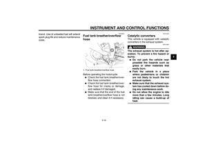 33
33 34
34 35
35 36
36 37
37 38
38 39
39 40
40 41
41 42
42 43
43 44
44 45
45 46
46 47
47 48
48 49
49 50
50 51
51 52
52 53
53 54
54 55
55 56
56 57
57 58
58 59
59 60
60 61
61 62
62 63
63 64
64 65
65 66
66 67
67 68
68 69
69 70
70 71
71 72
72 73
73 74
74 75
75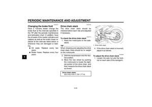 76
76 77
77 78
78 79
79 80
80 81
81 82
82 83
83 84
84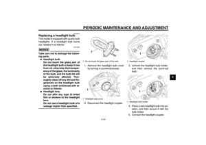 85
85 86
86 87
87 88
88 89
89 90
90 91
91 92
92 93
93 94
94 95
95 96
96 97
97 98
98 99
99 100
100 101
101 102
102 103
103 104
104 105
105 106
106 107
107