Page 89 of 108

PERIODIC MAINTENANCE AND ADJUSTMENT
6-38
6
EAU24360
Front wheel
EAU33923
To remove the front wheel
WARNING
EWA10821
To avoid injury, securely support the
vehicle so there is no danger of it
falling over.1. Loosen the front wheel axle pinch
bolts, the axle bolt, and then the
brake caliper bolts.
2. Lift the front wheel off the ground
according to the procedure on
page 6-37.3. Remove the brake hose holder on
each side by removing the bolt and
nut.
4. Remove the brake caliper on each
side by removing the bolts.
5. Remove the axle bolt, push the
wheel axle out from the left side,
and then remove the wheel.
NOTICE: Do not apply the brake
after the brake calipers have
been removed, otherwise the
brake pads will be forced shut.
[ECA11051]EAU33934
To install the front wheel
1. Lift the wheel up between the fork
legs.
2. Insert the wheel axle.
3. Install the axle bolt, and then lower
the front wheel so that it is on the
ground, and then put the sidestand
down.
4. Install the brake calipers by install-
ing the bolts, and then tightening
them to the specified torque.TIPMake sure that there is enough space
between the brake pads before install-
ing the brake calipers onto the brake
discs.
1. Front wheel axle pinch bolt
1. Brake hose holder
2. Bolt and nut
3. Brake caliper bolt
4. Brake caliper
5. Axle bolt
1. Wheel axle
U13SE2E0.book Page 38 Tuesday, August 4, 2009 4:01 PM
Page 90 of 108

PERIODIC MAINTENANCE AND ADJUSTMENT
6-39
65. Install the brake hose holders by
installing the bolts and nuts.
6. Tighten the axle bolt to the speci-
fied torque.
TIPWhile tightening the axle bolt, hold the
wheel axle with a 19-mm hexagon
wrench to keep it from turning.7. Tighten wheel axle pinch bolt B,
then pinch bolt A to the specified
torque.8. Retighten pinch bolt B to the spec-
ified torque.
9. Tap the outer side of the right fork
leg with a rubber mallet to align it
with the end of the wheel axle.
10. Tighten wheel axle pinch bolt D,
then pinch bolt C to the specified
torque.
11. Retighten pinch bolt D to the spec-
ified torque.12. While applying the front brake,
push down hard on the handlebar
several times to check for proper
fork operation.Tightening torque:
Brake caliper bolt:
35 Nm (3.5 m·kgf, 25 ft·lbf)
Tightening torque:
Axle bolt:
91 Nm (9.1 m·kgf, 66 ft·lbf)
1. Front wheel axle pinch bolt A
2. Front wheel axle pinch bolt B
3. Front wheel axle pinch bolt C
4. Front wheel axle pinch bolt DTightening torque:
Wheel axle pinch bolt:
21 Nm (2.1 m·kgf, 15 ft·lbf)
Tightening torque:
Wheel axle pinch bolt:
21 Nm (2.1 m·kgf, 15 ft·lbf)
U13SE2E0.book Page 39 Tuesday, August 4, 2009 4:01 PM
Page 91 of 108

PERIODIC MAINTENANCE AND ADJUSTMENT
6-40
6
EAU25080
Rear wheel
EAU44951
To remove the rear wheel
WARNING
EWA10821
To avoid injury, securely support the
vehicle so there is no danger of it
falling over.1. Loosen the axle nut.
2. Lift the rear wheel off the ground
according to the procedure on
page 6-37.
3. Remove the axle nut.4. Loosen the locknut on each side of
the swingarm.
5. Turn the drive chain slack adjust-
ing bolts in direction (a) to loosen
the drive chain enough so it can be
removed from the rear sprocket,
and then push the wheel forward.
6. Remove the drive chain from the
rear sprocket.
TIP�
If the drive chain is difficult to re-
move, remove the wheel axle first,
and then lift the wheel upward
enough to remove the drive chain
from the rear sprocket.
�
The drive chain cannot be disas-
sembled.
7. While supporting the brake caliper
bracket, pull the wheel axle out,
and then remove the wheel.
NOTICE: Do not apply the brake
after the wheel has been re-
moved together with the brake
disc, otherwise the brake pads
will be forced shut.
[ECA11071]
EAU39172
To install the rear wheel
1. Install the wheel and the brake cal-
iper bracket by inserting the wheel
axle from the left-hand side.TIP�
Be sure to insert the retainer on the
brake caliper bracket into the slot
in the swingarm.
1. Axle nut
2. Drive chain slack adjusting bolt
3. Locknut
4. Brake caliper
5. Brake caliper bracket
1. Wheel axle
U13SE2E0.book Page 40 Tuesday, August 4, 2009 4:01 PM
Page 92 of 108

PERIODIC MAINTENANCE AND ADJUSTMENT
6-41
6
�
Make sure that there is enough
space between the brake pads be-
fore installing the wheel.
2. Install the drive chain onto the rear
sprocket.
3. Install the axle nut, and then lower
the rear wheel so that it is on the
ground, and then put the sidestand
down.
4. Adjust the drive chain slack. (See
page 6-25.)
5. Tighten the axle nut to the speci-
fied torque.6. Tighten the adjusting bolts in direc-
tion (b) to their specified torque.
7. Tighten the locknuts to their speci-
fied torque.
EAU25871
Troubleshooting Although Yamaha motorcycles receive
a thorough inspection before shipment
from the factory, trouble may occur dur-
ing operation. Any problem in the fuel,
compression, or ignition systems, for
example, can cause poor starting and
loss of power.
The following troubleshooting charts
represent quick and easy procedures
for checking these vital systems your-
self. However, should your motorcycle
require any repair, take it to a Yamaha
dealer, whose skilled technicians have
the necessary tools, experience, and
know-how to service the motorcycle
properly.
Use only genuine Yamaha replace-
ment parts. Imitation parts may look like
Yamaha parts, but they are often inferi-
or, have a shorter service life and can
lead to expensive repair bills.
WARNING
EWA15141
When checking the fuel system, do
not smoke, and make sure there are
no open flames or sparks in the ar-
ea, including pilot lights from water
1. Retainer
2. SlotTightening torque:
Axle nut:
110 Nm (11.0 m·kgf, 80 ft·lbf)
Tightening torque:
Drive chain slack adjusting bolt:
2 Nm (0.2 m·kgf, 1.4 ft·lbf)
Tightening torque:
Locknut:
16 Nm (1.6 m·kgf, 11 ft·lbf)
U13SE2E0.book Page 41 Tuesday, August 4, 2009 4:01 PM
Page 93 of 108
PERIODIC MAINTENANCE AND ADJUSTMENT
6-42
6 heaters or furnaces. Gasoline or
gasoline vapors can ignite or ex-
plode, causing severe injury or
property damage.
U13SE2E0.book Page 42 Tuesday, August 4, 2009 4:01 PM
Page 94 of 108

PERIODIC MAINTENANCE AND ADJUSTMENT
6-43
6
EAU42501
Troubleshooting charts Starting problems or poor engine performance
Check the fuel level in
the fuel tank.1. Fuel
There is enough fuel.
There is no fuel.
Check the compression.
Supply fuel.
The engine does not start.
Check the compression.
Operate the electric starter.2. Compression
There is compression.
There is no compression.
Check the ignition.
Have a Yamaha dealer
check the vehicle.
Remove the spark plugs
and check the electrodes.3. Ignition
Wipe off with a dry cloth and correct the
spark plug gaps, or replace the spark plugs.
Have a Yamaha dealer check the vehicle.
The engine does not start.
Have a Yamaha dealer
check the vehicle.
The engine does not start.
Check the battery.
Operate the electric starter.4. Battery
The engine turns over
quickly.
The engine turns over
slowly.
The battery is good.Check the battery lead connections,
and charge the battery if necessary.
DryWet
Operate the electric starter.
U13SE2E0.book Page 43 Tuesday, August 4, 2009 4:01 PM
Page 95 of 108

PERIODIC MAINTENANCE AND ADJUSTMENT
6-44
6 Engine overheating
WARNING
EWAT1040
�
Do not remove the radiator cap when the engine and radiator are hot. Scalding hot fluid and steam may be
blown out under pressure, which could cause serious injury. Be sure to wait until the engine has cooled.
�
Place a thick rag, like a towel, over the radiator cap, and then slowly rotate the cap counterclockwise to the de-
tent to allow any residual pressure to escape. When the hissing sound has stopped, press down on the cap
while turning it counterclockwise, and then remove the cap.
TIPIf coolant is not available, tap water can be temporarily used instead, provided that it is changed to the recommended coolant
as soon as possible.
Wait until the
engine has cooled.
Check the coolant level in the
reservoir and radiator.
The coolant level
is OK.The coolant level is low.
Check the cooling system
for leakage.
Have a Yamaha dealer checkand repair the cooling system.Add coolant. (See TIP.)
Start the engine. If the engine overheats again,
have a
Yamaha dealer check
and repair the cooling system.
There is
leakage.
There is
no leakage.
U13SE2E0.book Page 44 Tuesday, August 4, 2009 4:01 PM
Page 96 of 108

MOTORCYCLE CARE AND STORAGE
7-1
7
EAU37833
Matte color caution NOTICE
ECA15192
Some models are equipped with
matte colored finished parts. Be
sure to consult a Yamaha dealer for
advice on what products to use be-
fore cleaning the vehicle. Using a
brush, harsh chemical products or
cleaning compounds when cleaning
these parts will scratch or damage
their surface. Wax also should not
be applied to any matte colored fin-
ished parts.
EAU26023
Care While the open design of a motorcycle
reveals the attractiveness of the tech-
nology, it also makes it more vulnera-
ble. Rust and corrosion can develop
even if high-quality components are
used. A rusty exhaust pipe may go un-
noticed on a car, however, it detracts
from the overall appearance of a motor-
cycle. Frequent and proper care does
not only comply with the terms of the
warranty, but it will also keep your mo-
torcycle looking good, extend its life
and optimize its performance.
Before cleaning
1. Cover the muffler outlet with a
plastic bag after the engine has
cooled down.
2. Make sure that all caps and covers
as well as all electrical couplers
and connectors, including the
spark plug caps, are tightly in-
stalled.
3. Remove extremely stubborn dirt,
like oil burnt onto the crankcase,
with a degreasing agent and a
brush, but never apply such prod-ucts onto seals, gaskets, sprock-
ets, the drive chain and wheel
axles. Always rinse the dirt and de-
greaser off with water.
Cleaning
NOTICE
ECA11142
�
Avoid using strong acidic wheel
cleaners, especially on spoked
wheels. If such products are
used on hard-to-remove dirt, do
not leave the cleaner on the af-
fected area any longer than in-
structed. Also, thoroughly rinse
the area off with water, immedi-
ately dry it, and then apply a cor-
rosion protection spray.
�
Improper cleaning can damage
plastic parts (such as cowlings,
panels, windshields, headlight
lenses, meter lenses, etc.) and
the mufflers. Use only a soft,
clean cloth or sponge with wa-
ter to clean plastic. However, if
the plastic parts cannot be thor-
oughly cleaned with water, di-
luted mild detergent with water
may be used. Be sure to rinse
U13SE2E0.book Page 1 Tuesday, August 4, 2009 4:01 PM
 1
1 2
2 3
3 4
4 5
5 6
6 7
7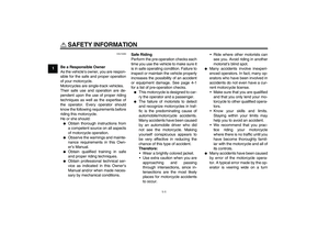 8
8 9
9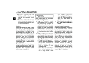 10
10 11
11 12
12 13
13 14
14 15
15 16
16 17
17 18
18 19
19 20
20 21
21 22
22 23
23 24
24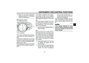 25
25 26
26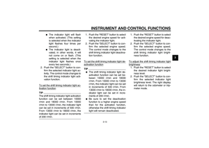 27
27 28
28 29
29 30
30 31
31 32
32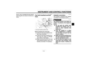 33
33 34
34 35
35 36
36 37
37 38
38 39
39 40
40 41
41 42
42 43
43 44
44 45
45 46
46 47
47 48
48 49
49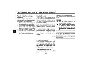 50
50 51
51 52
52 53
53 54
54 55
55 56
56 57
57 58
58 59
59 60
60 61
61 62
62 63
63 64
64 65
65 66
66 67
67 68
68 69
69 70
70 71
71 72
72 73
73 74
74 75
75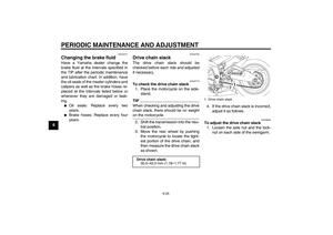 76
76 77
77 78
78 79
79 80
80 81
81 82
82 83
83 84
84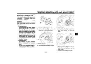 85
85 86
86 87
87 88
88 89
89 90
90 91
91 92
92 93
93 94
94 95
95 96
96 97
97 98
98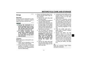 99
99 100
100 101
101 102
102 103
103 104
104 105
105 106
106 107
107