Page 33 of 108

INSTRUMENT AND CONTROL FUNCTIONS
3-19
3 brand. Use of unleaded fuel will extend
spark plug life and reduce maintenance
costs.
EAU39451
Fuel tank breather/overflow
hose Before operating the motorcycle:�
Check the fuel tank breather/over-
flow hose connection.
�
Check the fuel tank breather/over-
flow hose for cracks or damage,
and replace it if damaged.
�
Make sure that the end of the fuel
tank breather/overflow hose is not
blocked, and clean it if necessary.
EAU13445
Catalytic converters This vehicle is equipped with catalytic
converters in the exhaust system.
WARNING
EWA10862
The exhaust system is hot after op-
eration. To prevent a fire hazard or
burns:�
Do not park the vehicle near
possible fire hazards such as
grass or other materials that
easily burn.
�
Park the vehicle in a place
where pedestrians or children
are not likely to touch the hot
exhaust system.
�
Make sure that the exhaust sys-
tem has cooled down before do-
ing any maintenance work.
�
Do not allow the engine to idle
more than a few minutes. Long
idling can cause a build-up of
heat.
1. Fuel tank breather/overflow hose
U13SE2E0.book Page 19 Tuesday, August 4, 2009 4:01 PM
Page 34 of 108
INSTRUMENT AND CONTROL FUNCTIONS
3-20
3
NOTICE
ECA10701
Use only unleaded gasoline. The use
of leaded gasoline will cause unre-
pairable damage to the catalytic
converter.
EAU39032
Seats Rider seat
To remove the rider seatPull back the rear of the rider seat as
shown, remove the bolts, and then pull
the seat off.
To install the rider seatInsert the projection on the front of the
rider seat into the seat holder as
shown, place the seat in the original po-
sition, and then install the bolts.Passenger seat
To remove the passenger seat
1. Insert the key into the passenger
seat lock, and then turn it clock-
wise.
1. Bolt
1. Projection
2. Seat holder
U13SE2E0.book Page 20 Tuesday, August 4, 2009 4:01 PM
Page 35 of 108
INSTRUMENT AND CONTROL FUNCTIONS
3-21
3
2. While holding the key in that posi-
tion, lift the front of the passenger
seat and pull it forward.
To install the passenger seat
1. Insert the projections on the pas-
senger seat into the seat holders
as shown, and then push the front
of the seat down to lock it in place.2. Remove the key.
TIPMake sure that the seats are properly
secured before riding.
EAU39073
Helmet holding cable A helmet holding cable is provided in
the owner’s tool kit to secure two hel-
mets to the helmet cable holder
equipped on the bottom of the passen-
ger seat.
To secure a helmet with the helmet
holding cable
1. Remove the passenger seat. (See
page 3-20.)
2. Clip the middle snap hook of the
cable onto the cable holder.
1. Passenger seat lock
2. Unlock.
1. Projection
2. Seat holder
1. Helmet holding cable
2. Helmet cable holder
3. Middle snap hook
U13SE2E0.book Page 21 Tuesday, August 4, 2009 4:01 PM
Page 36 of 108

INSTRUMENT AND CONTROL FUNCTIONS
3-22
33. Pass one of the other snap hooks
of the cable through the helmet
strap buckle, and then clip the
snap hook onto the cable holder as
shown.
4. Install the passenger seat.
WARNING! Never ride with a
helmet attached to a helmet
holding cable, since the helmet
may hit objects, causing loss of
control and possibly an acci-
dent.
[EWA14331]
To release a helmet from the helmet
holding cable
1. Remove the passenger seat.
2. Unfasten the snap hooks from the
cable holder, and then remove the
cable from the helmet strap buck-
le.
3. Install the passenger seat.
EAU39671
Rear view mirrors The rear view mirrors of this vehicle can
be folded forward or backward for park-
ing in narrow spaces. Fold the mirrors
back to their original position before
riding.
WARNING
EWA14371
Be sure to fold the rear view mirrors
back to their original position before
riding.
1. Snap hook
2. Helmet holding cable
3. Helmet
1
2
3
1. Helmet holding cable
2. Helmet
1. Riding position
2. Parking position
2
2
1
2
2
1
U13SE2E0.book Page 22 Tuesday, August 4, 2009 4:01 PM
Page 37 of 108

INSTRUMENT AND CONTROL FUNCTIONS
3-23
3
EAU38943
Adjusting the front fork
WARNING
EWA10180
Always adjust both fork legs equal-
ly, otherwise poor handling and loss
of stability may result.This front fork is equipped with spring
preload adjusting bolts, rebound damp-
ing force adjusting screws, compres-
sion damping force adjusting bolts (for
fast compression damping) and com-
pression damping force adjusting bolts
(for slow compression damping).NOTICE
ECA10101
To avoid damaging the mechanism,
do not attempt to turn beyond the
maximum or minimum settings.
Spring preload
To increase the spring preload and
thereby harden the suspension, turn
the adjusting bolt on each fork leg in di-
rection (a). To decrease the spring pre-
load and thereby soften the
suspension, turn the adjusting bolt on
each fork leg in direction (b).
Align the appropriate groove on the ad-
justing mechanism with the top of the
front fork collar.1. Spring preload adjusting bolt
1
1
(a)(b)
1. Current setting
2. Front fork collar
Spring preload setting:
Minimum (soft):
0
Standard:
2
Maximum (hard):
5
U13SE2E0.book Page 23 Tuesday, August 4, 2009 4:01 PM
Page 38 of 108
.")
INSTRUMENT AND CONTROL FUNCTIONS
3-24
3Rebound damping force
To increase the rebound damping force
and thereby harden the rebound damp-
ing, turn the adjusting screw on each
fork leg in direction (a). To decrease the
rebound damping force and thereby
soften the rebound damping, turn the
adjusting screw on each fork leg in di-
rection (b).Compression damping force
To adjust the compression damping
force (for fast compression damping)To increase the compression damping
force and thereby harden the compres-
sion damping, turn the adjusting bolt on
each fork leg in direction (a). To de-
crease the compression damping force
and thereby soften the compression
damping, turn the adjusting bolt on
each fork leg in direction (b).To adjust the compression damping
force (for slow compression damping)To increase the compression damping
force and thereby harden the compres-
sion damping, turn the adjusting bolt on
each fork leg in direction (a). To de-
crease the compression damping force
1. Rebound damping force adjusting screwRebound damping setting:
Minimum (soft):
25 click(s) in direction (b)*
Standard:
20 click(s) in direction (b)*
Maximum (hard):
1 click(s) in direction (b)*
* With the adjusting screw fully turned
in direction (a)
1
1
(a)(b)
1. Compression damping force adjusting bolt
(for fast compression damping)
1
1
(a)
(b)
Compression damping setting (for
fast compression damping):
Minimum (soft):
4 turn(s) in direction (b)*
Standard:
2 turn(s) in direction (b)*
Maximum (hard):
0 turn(s) in direction (b)*
* With the adjusting bolt fully turned in
direction (a) 1. Compression damping force adjusting bolt
(for slow compression damping)
1
1
(a)
(b)
U13SE2E0.book Page 24 Tuesday, August 4, 2009 4:01 PM
Page 39 of 108
.
TIPAlthough the total number of clicks of a
damping force")
INSTRUMENT AND CONTROL FUNCTIONS
3-25
3 and thereby soften the compression
damping, turn the adjusting bolt on
each fork leg in direction (b).
TIPAlthough the total number of clicks of a
damping force adjusting mechanism
may not exactly match the above spec-
ifications due to small differences in
production, the actual number of clicks
always represents the entire adjusting
range. To obtain a precise adjustment,
it would be advisable to check the num-
ber of clicks of each damping force ad-
justing mechanism and to modify the
specifications as necessary.
EAU42944
Adjusting the shock absorber
assembly This shock absorber assembly is
equipped with a spring preload adjust-
ing ring, a rebound damping force ad-
justing screw, a compression damping
force adjusting bolt (for fast compres-
sion damping) and a compression
damping force adjusting bolt (for slow
compression damping).NOTICE
ECA10101
To avoid damaging the mechanism,
do not attempt to turn beyond the
maximum or minimum settings.
Spring preload
To increase the spring preload and
thereby harden the suspension, turn
the adjusting ring in direction (a). To de-
crease the spring preload and thereby
soften the suspension, turn the adjust-
ing ring in direction (b).�
Align the appropriate notch in the
adjusting ring with the position in-
dicator on the shock absorber.
�
Use the special wrench and the
extension bar included in the own-
er’s tool kit to make the adjust-
ment.
Compression damping setting (for
slow compression damping):
Minimum (soft):
20 click(s) in direction (b)*
Standard:
15 click(s) in direction (b)*
Maximum (hard):
1 click(s) in direction (b)*
* With the adjusting bolt fully turned in
direction (a)
1. Spring preload adjusting ring
2. Position indicator
3. Extension bar
4. Special wrench
1
4
32
U13SE2E0.book Page 25 Tuesday, August 4, 2009 4:01 PM
Page 40 of 108
. To decrease the")
INSTRUMENT AND CONTROL FUNCTIONS
3-26
3
Rebound damping force
To increase the rebound damping force
and thereby harden the rebound damp-
ing, turn the adjusting screw in direction
(a). To decrease the rebound damping
force and thereby soften the rebound
damping, turn the adjusting screw in di-
rection (b).Compression damping force
Compression damping force (for fast
compression damping)To increase the compression damping
force and thereby harden the compres-
sion damping, turn the adjusting bolt in
direction (a). To decrease the compres-sion damping force and thereby soften
the compression damping, turn the ad-
justing bolt in direction (b).
Compression damping force (for slow
compression damping)
Spring preload setting:
Minimum (soft):
1
Standard:
4
Maximum (hard):
91. Rebound damping force adjusting screw
Rebound damping setting:
Minimum (soft):
20 click(s) in direction (b)*
Standard:
16 click(s) in direction (b)*
Maximum (hard):
3 click(s) in direction (b)*
* With the adjusting screw fully turned
in direction (a) 1. Compression damping force adjusting bolt
(for fast compression damping)
1
1
(a)
(b)
Compression damping setting (for
fast compression damping):
Minimum (soft):
4 turn(s) in direction (b)*
Standard:
3 turn(s) in direction (b)*
Maximum (hard):
0 turn(s) in direction (b)*
* With the adjusting bolt fully turned in
direction (a) 1. Compression damping force adjusting bolt
(for slow compression damping)
1
1
(a)
(b)
U13SE2E0.book Page 26 Tuesday, August 4, 2009 4:01 PM
 1
1 2
2 3
3 4
4 5
5 6
6 7
7 8
8 9
9 10
10 11
11 12
12 13
13 14
14 15
15 16
16 17
17 18
18 19
19 20
20 21
21 22
22 23
23 24
24 25
25 26
26 27
27 28
28 29
29 30
30 31
31 32
32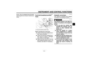 33
33 34
34 35
35 36
36 37
37 38
38 39
39 40
40 41
41 42
42 43
43 44
44 45
45 46
46 47
47 48
48 49
49 50
50 51
51 52
52 53
53 54
54 55
55 56
56 57
57 58
58 59
59 60
60 61
61 62
62 63
63 64
64 65
65 66
66 67
67 68
68 69
69 70
70 71
71 72
72 73
73 74
74 75
75 76
76 77
77 78
78 79
79 80
80 81
81 82
82 83
83 84
84 85
85 86
86 87
87 88
88 89
89 90
90 91
91 92
92 93
93 94
94 95
95 96
96 97
97 98
98 99
99 100
100 101
101 102
102 103
103 104
104 105
105 106
106 107
107
