Page 57 of 108
PERIODIC MAINTENANCE AND ADJUSTMENT
6-6
6
EAU18680
TIP�
Air filter
This model’s air filter is equipped with a disposable oil-coated paper element, which must not be cleaned with com-
pressed air to avoid damaging it.
The air filter element needs to be replaced more frequently when riding in unusually wet or dusty areas.
�
Hydraulic brake service
Regularly check and, if necessary, correct the brake fluid level.
Every two years replace the internal components of the brake master cylinders and calipers, and change the brake
fluid.
Replace the brake hoses every four years and if cracked or damaged.
U13SE2E0.book Page 6 Tuesday, August 4, 2009 4:01 PM
Page 58 of 108
PERIODIC MAINTENANCE AND ADJUSTMENT
6-7
6
EAU18712
Removing and installing cowl-
ings and panels The cowlings and panels shown need
to be removed to perform some of the
maintenance jobs described in this
chapter. Refer to this section each time
a cowling or panel needs to be re-
moved and installed.
EAU44931
Cowlings A and B
To remove one of the cowlings1. Remove the bolts, quick fasteners,
and quick fastener screw.
1. Cowling A
1. Cowling B
2. Cowling C
1. Panel A
2. Panel B
2
1
1. Cowling A
2. Bolt
3. Quick fastener
1. Quick fastener
2
3
12
2
2
U13SE2E0.book Page 7 Tuesday, August 4, 2009 4:01 PM
Page 59 of 108
PERIODIC MAINTENANCE AND ADJUSTMENT
6-8
6
2. Remove the projection on cowling
A from the hole in cowling B as
shown.3. Remove the forward-most projec-
tion from the slot, slide the cowling
forward, and then remove the re-
maining projections from the slots
as shown.
4. Disconnect the turn signal light
lead coupler.
1. Quick fastener
2. Quick fastener screw
1. Cowling B
2. Bolt
3. Quick fastener
1. Quick fastener
1. Quick fastener
2. Quick fastener screw
1. Cowling A
2. Cowling B
U13SE2E0.book Page 8 Tuesday, August 4, 2009 4:01 PM
Page 60 of 108
PERIODIC MAINTENANCE AND ADJUSTMENT
6-9
6
To install the cowling
1. Connect the turn signal light lead
coupler.2. Fit the projections into the slots,
slide the cowling rearward, and
then fit the forward-most projection
into the slot.3. Fit the projection on cowling A into
the hole in cowling B as shown.
4. Install the bolts, quick fasteners,
and quick fastener screw.
EAU39092
Cowling C
To remove the cowling1. Remove cowling B and panel B.
(See page 6-7.)
2. Unfasten the wire harness by
pressing on the projection to open
the plastic fastener.
1. Cowling A
2. Turn signal light lead coupler
1. Cowling B
2. Turn signal light lead coupler
1. Cowling A
2. Turn signal light lead coupler
1. Cowling B
2. Turn signal light lead coupler
1. Cowling A
2. Cowling B
U13SE2E0.book Page 9 Tuesday, August 4, 2009 4:01 PM
Page 61 of 108
PERIODIC MAINTENANCE AND ADJUSTMENT
6-10
6 3. Remove the bolts and the quick
fastener, and then pull the cowling
off as shown.To install the cowling
1. Fit the slot in cowling C over the
projection on the front cowling.
2. Install the bolts and the quick fas-
tener.
3. Place the wire harness in the orig-
inal position, and then close the
plastic fastener.
4. Install the cowling and the panel.
EAU39061
Panels A and B
To remove one of the panelsRemove the bolts, and then pull the
panel off as shown.To install the panel
Place the panel in the original position,
and then install the bolts.
1. Plastic fastener
2. Projection
3. Wire harness
1. Cowling C
2. Bolt
3. Quick fastener
1. Cowling C
2. Slot
3. Front cowling
4. Projection
1. Panel B
2. Bolt
U13SE2E0.book Page 10 Tuesday, August 4, 2009 4:01 PM
Page 62 of 108

PERIODIC MAINTENANCE AND ADJUSTMENT
6-11
6
EAU19652
Checking the spark plugs The spark plugs are important engine
components, which should be checked
periodically, preferably by a Yamaha
dealer. Since heat and deposits will
cause any spark plug to slowly erode,
they should be removed and checked
in accordance with the periodic mainte-
nance and lubrication chart. In addition,
the condition of the spark plugs can re-
veal the condition of the engine.
The porcelain insulator around the cen-
ter electrode of each spark plug should
be a medium-to-light tan (the ideal color
when the vehicle is ridden normally),
and all spark plugs installed in the en-
gine should have the same color. If any
spark plug shows a distinctly different
color, the engine could be operating im-
properly. Do not attempt to diagnose
such problems yourself. Instead, have
a Yamaha dealer check the vehicle.
If a spark plug shows signs of electrode
erosion and excessive carbon or other
deposits, it should be replaced.Before installing a spark plug, the spark
plug gap should be measured with a
wire thickness gauge and, if necessary,
adjusted to specification.
Clean the surface of the spark plug
gasket and its mating surface, and then
wipe off any grime from the spark plug
threads.
TIPIf a torque wrench is not available when
installing a spark plug, a good estimate
of the correct torque is 1/4–1/2 turn
past finger tight. However, the spark
plug should be tightened to the speci-
fied torque as soon as possible.NOTICE
ECA10840
Do not use any tools to remove or in-
stall the spark plug cap, otherwise
the ignition coil coupler may get
damaged. The spark plug cap may
be difficult to remove because the
rubber seal on the end of the cap fits
tightly. To remove the spark plug
cap, simply twist it back and forth
while pulling it out; to install it, twist
it back and forth while pushing it in.
Specified spark plug:
NGK/CR10EK
1. Spark plug gapSpark plug gap:
0.6–0.7 mm (0.024–0.028 in)
Tightening torque:
Spark plug:
12.5 Nm (1.25 m·kgf, 9.0 ft·lbf)
U13SE2E0.book Page 11 Tuesday, August 4, 2009 4:01 PM
Page 63 of 108

PERIODIC MAINTENANCE AND ADJUSTMENT
6-12
6
EAU3899A
Engine oil and oil filter car-
tridge The engine oil level should be checked
before each ride. In addition, the oil
must be changed and the oil filter car-
tridge replaced at the intervals speci-
fied in the periodic maintenance and
lubrication chart.
To check the engine oil level
1. Place the vehicle on a level sur-
face and hold it in an upright posi-
tion. A slight tilt to the side can
result in a false reading.
2. Start the engine, warm it up for
several minutes, and then turn it
off.
3. Wait a few minutes until the oil set-
tles.
4. Remove the engine oil dipstick and
wipe it clean, insert it back into the
hole (without screwing it in), and
then remove it again to check the
oil level.TIPThe engine oil should be between the
minimum and maximum level marks.
5. If the engine oil is at or below the
minimum level mark, remove the
engine oil filler cap, and then add
sufficient oil of the recommended
type to raise it to the correct level.6. Insert and tighten the engine oil
dipstick, and then install and tight-
en the oil filler cap.
To change the engine oil (with or
without oil filter cartridge replace-
ment)
1. Place the vehicle on a level sur-
face.
2. Remove cowling A. (See page
6-7.)
3. Start the engine, warm it up for
several minutes, and then turn it
off.
4. Place an oil pan under the engine
to collect the used oil.
5. Remove the engine oil filler cap,
the engine oil drain bolt and its
gasket to drain the oil from the
crankcase.1. Engine oil dipstick
2. Maximum level mark
3. Minimum level mark
1. Engine oil filler cap
U13SE2E0.book Page 12 Tuesday, August 4, 2009 4:01 PM
Page 64 of 108
PERIODIC MAINTENANCE AND ADJUSTMENT
6-13
6
TIPSkip steps 6–12 if the oil filter cartridge
is not being replaced.6. Remove the shift arm by removing
the bolt and pulling it off the shift
shaft.
7. Remove the fuel tank breath-
er/overflow hoses from the guides.8. Remove the oil filter cartridge with
an oil filter wrench.
TIPAn oil filter wrench is available at a
Yamaha dealer.9. Apply a thin coat of clean engine
oil to the O-ring of the new oil filter
cartridge.TIPMake sure that the O-ring is properly
seated.10. Install the new oil filter cartridge
with an oil filter wrench, and then
tighten it to the specified torque
with a torque wrench.
1. Engine oil drain bolt
2. Gasket
1
1
2
1. Bolt
2. Shift arm
3. Engine oil filter cartridge
4. Guide
5. Fuel tank breather/overflow hose
1. Oil filter wrench
1. O-ring
U13SE2E0.book Page 13 Tuesday, August 4, 2009 4:01 PM
 1
1 2
2 3
3 4
4 5
5 6
6 7
7 8
8 9
9 10
10 11
11 12
12 13
13 14
14 15
15 16
16 17
17 18
18 19
19 20
20 21
21 22
22 23
23 24
24 25
25 26
26 27
27 28
28 29
29 30
30 31
31 32
32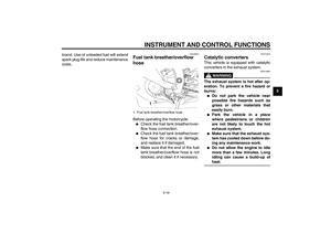 33
33 34
34 35
35 36
36 37
37 38
38 39
39 40
40 41
41 42
42 43
43 44
44 45
45 46
46 47
47 48
48 49
49 50
50 51
51 52
52 53
53 54
54 55
55 56
56 57
57 58
58 59
59 60
60 61
61 62
62 63
63 64
64 65
65 66
66 67
67 68
68 69
69 70
70 71
71 72
72 73
73 74
74 75
75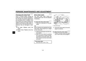 76
76 77
77 78
78 79
79 80
80 81
81 82
82 83
83 84
84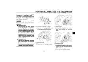 85
85 86
86 87
87 88
88 89
89 90
90 91
91 92
92 93
93 94
94 95
95 96
96 97
97 98
98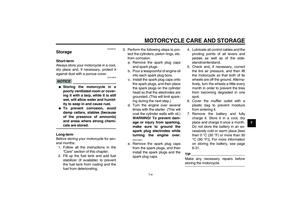 99
99 100
100 101
101 102
102 103
103 104
104 105
105 106
106 107
107


