Page 81 of 108

PERIODIC MAINTENANCE AND ADJUSTMENT
6-30
6
EAUM1651
Lubricating the swingarm piv-
ots The swingarm pivots must be lubricat-
ed by a Yamaha dealer at the intervals
specified in the periodic maintenance
and lubrication chart.
EAU23272
Checking the front fork The condition and operation of the front
fork must be checked as follows at the
intervals specified in the periodic main-
tenance and lubrication chart.
To check the condition
Check the inner tubes for scratches,
damage and excessive oil leakage.
To check the operation
1. Place the vehicle on a level sur-
face and hold it in an upright posi-
tion. WARNING! To avoid injury,
securely support the vehicle so
there is no danger of it falling
over.
[EWA10751]
2. While applying the front brake,
push down hard on the handlebars
several times to check if the front
fork compresses and rebounds
smoothly.
NOTICE
ECA10590
If any damage is found or the front
fork does not operate smoothly,
have a Yamaha dealer check or re-
pair it.
Recommended lubricant:
Lithium-soap-based grease
U13SE2E0.book Page 30 Tuesday, August 4, 2009 4:01 PM
Page 82 of 108

PERIODIC MAINTENANCE AND ADJUSTMENT
6-31
6
EAU23283
Checking the steering Worn or loose steering bearings may
cause danger. Therefore, the operation
of the steering must be checked as fol-
lows at the intervals specified in the pe-
riodic maintenance and lubrication
chart.
1. Place a stand under the engine to
raise the front wheel off the
ground. (See page 6-37 for more
information.) WARNING! To
avoid injury, securely support
the vehicle so there is no danger
of it falling over.
[EWA10751]
2. Hold the lower ends of the front
fork legs and try to move them for-
ward and backward. If any free
play can be felt, have a Yamaha
dealer check or repair the steering.
EAU23291
Checking the wheel bearings The front and rear wheel bearings must
be checked at the intervals specified in
the periodic maintenance and lubrica-
tion chart. If there is play in the wheel
hub or if the wheel does not turn
smoothly, have a Yamaha dealer check
the wheel bearings.
EAU23444
Battery This model is equipped with a VRLA
(Valve Regulated Lead Acid) battery.
There is no need to check the electro-
lyte or to add distilled water. However,
the battery lead connections need to be
checked and, if necessary, tightened.
WARNING
EWA10760
�
Electrolyte is poisonous and
dangerous since it contains sul-
furic acid, which causes severe
burns. Avoid any contact with
skin, eyes or clothing and al-
ways shield your eyes when
1. Battery
2. Negative battery lead (black)
3. Positive battery lead (red)
U13SE2E0.book Page 31 Tuesday, August 4, 2009 4:01 PM
Page 83 of 108

PERIODIC MAINTENANCE AND ADJUSTMENT
6-32
6 working near batteries. In case
of contact, administer the fol-
lowing FIRST AID.
EXTERNAL: Flush with plenty
of water.
INTERNAL: Drink large quan-
tities of water or milk and im-
mediately call a physician.
EYES: Flush with water for 15
minutes and seek prompt
medical attention.
�
Batteries produce explosive hy-
drogen gas. Therefore, keep
sparks, flames, cigarettes, etc.,
away from the battery and pro-
vide sufficient ventilation when
charging it in an enclosed
space.
�
KEEP THIS AND ALL BATTER-
IES OUT OF THE REACH OF
CHILDREN.
To charge the battery
Have a Yamaha dealer charge the bat-
tery as soon as possible if it seems to
have discharged. Keep in mind that the
battery tends to discharge more quickly
if the vehicle is equipped with optional
electrical accessories.
NOTICE
ECA16520
To charge a VRLA (Valve Regulated
Lead Acid) battery, a special (con-
stant-voltage) battery charger is re-
quired. Using a conventional battery
charger will damage the battery. If
you do not have access to a con-
stant-voltage battery charger, have a
Yamaha dealer charge your battery.To store the battery
1. If the vehicle will not be used for
more than one month, remove the
battery, fully charge it, and then
place it in a cool, dry place.
NOTICE: When removing the
battery, be sure the key is
turned to “OFF”, then discon-
nect the negative lead before
disconnecting the positive lead.
[ECA16302]
2. If the battery will be stored for more
than two months, check it at least
once a month and fully charge it if
necessary.
3. Fully charge the battery before in-
stallation.4. After installation, make sure that
the battery leads are properly con-
nected to the battery terminals.
NOTICE
ECA16530
Always keep the battery charged.
Storing a discharged battery can
cause permanent battery damage.
U13SE2E0.book Page 32 Tuesday, August 4, 2009 4:01 PM
Page 84 of 108

Fuse box 2 is l")
PERIODIC MAINTENANCE AND ADJUSTMENT
6-33
6
EAU23705
Replacing the fuses The main fuse, the fuel injection system
fuse, and fuse box 1 are located under
the rider seat. (See page 3-20.)
Fuse box 2 is located under panel A.
(See page 6-7.)If a fuse is blown, replace it as follows.
1. Turn the key to “OFF” and turn off
the electrical circuit in question.
2. Remove the blown fuse, and then
install a new fuse of the specified
amperage. WARNING! Do not
use a fuse of a higher amperage
rating than recommended to
avoid causing extensive dam-
age to the electrical system and
possibly a fire.
[EWA15131]
3. Turn the key to “ON” and turn on
the electrical circuit in question to
check if the device operates.
4. If the fuse immediately blows
again, have a Yamaha dealer
check the electrical system.
1. Main fuse
2. Fuel injection system spare fuse
3. Fuel injection system fuse
4. Fuse box 1
5. Backup fuse (for clock and immobilizer sys-
tem)
6. Electronic throttle valve fuse
7. Spare fuse
1. Fuse box 2
2. Left radiator fan fuse
3. Right radiator fan fuse
4. Signaling system fuse
5. Ignition fuse
6. Taillight fuse
7. Headlight fuse
8. Spare fuse
Specified fuses:
Main fuse:
50.0 A
Fuel injection system fuse:
15.0 A
Electronic throttle valve fuse:
7.5 A
Backup fuse:
7.5 A
Radiator fan fuse:
15.0 A × 2
Ignition fuse:
15.0 A
Signaling system fuse:
10.0 A
Taillight fuse:
7.5 A
Headlight fuse:
15.0 A
U13SE2E0.book Page 33 Tuesday, August 4, 2009 4:01 PM
Page 85 of 108

PERIODIC MAINTENANCE AND ADJUSTMENT
6-34
6
EAU39012
Replacing a headlight bulb This model is equipped with quartz bulb
headlights. If a headlight bulb burns
out, replace it as follows.NOTICE
ECA10650
Take care not to damage the follow-
ing parts:�
Headlight bulb
Do not touch the glass part of
the headlight bulb to keep it free
from oil, otherwise the transpar-
ency of the glass, the luminosity
of the bulb, and the bulb life will
be adversely affected. Thor-
oughly clean off any dirt and fin-
gerprints on the headlight bulb
using a cloth moistened with al-
cohol or thinner.
�
Headlight lens
Do not affix any type of tinted
film or stickers to the headlight
lens.
Do not use a headlight bulb of a
wattage higher than specified.
1. Remove the headlight bulb cover
by turning it counterclockwise.
2. Disconnect the headlight coupler.3. Unhook the headlight bulb holder,
and then remove the burnt-out
bulb.
4. Place a new headlight bulb into po-
sition, and then secure it with the
bulb holder.
5. Connect the headlight coupler.1. Do not touch the glass part of the bulb.
1. Headlight bulb cover
1. Headlight coupler
1. Headlight bulb holder
U13SE2E0.book Page 34 Tuesday, August 4, 2009 4:01 PM
Page 86 of 108
PERIODIC MAINTENANCE AND ADJUSTMENT
6-35
66. Install the headlight bulb cover by
turning it clockwise.
7. Have a Yamaha dealer adjust the
headlight beam if necessary.
EAU24181
Tail/brake light This model is equipped with an LED-
type tail/brake light.
If the tail/brake light does not come on,
have a Yamaha dealer check it.
EAU24204
Replacing a turn signal light
bulb 1. Remove the turn signal light lens
by removing the screw.
2. Remove the burnt-out bulb by
pushing it in and turning it counter-
clockwise.1. Screw
U13SE2E0.book Page 35 Tuesday, August 4, 2009 4:01 PM
Page 87 of 108
PERIODIC MAINTENANCE AND ADJUSTMENT
6-36
6 3. Insert a new bulb into the socket,
push it in, and then turn it clock-
wise until it stops.
4. Install the lens by installing the
screw. NOTICE: Do not over-
tighten the screw, otherwise the
lens may break.
[ECA11191]EAU24312
Replacing the license plate
light bulb 1. Remove the license plate light unit
by removing the screws.
2. Remove the socket (together with
the bulb) by pulling it out.3. Remove the burnt-out bulb by pull-
ing it out.
4. Insert a new bulb into the socket.
5. Install the socket (together with the
bulb) by pushing it in.
6. Install the license plate light unit by
installing the screws.
1. Turn signal light bulb
1. Screw
1. License plate light bulb
2. License plate light unit
U13SE2E0.book Page 36 Tuesday, August 4, 2009 4:01 PM
Page 88 of 108

PERIODIC MAINTENANCE AND ADJUSTMENT
6-37
6
EAU44940
Auxiliary light This model is equipped with an LED-
type auxiliary light.
If the auxiliary light does not come on,
have a Yamaha dealer check it.
EAU24350
Supporting the motorcycle Since this model is not equipped with a
centerstand, follow these precautions
when removing the front and rear
wheel or performing other maintenance
requiring the motorcycle to stand up-
right. Check that the motorcycle is in a
stable and level position before starting
any maintenance. A strong wooden
box can be placed under the engine for
added stability.
To service the front wheel
1. Stabilize the rear of the motorcycle
by using a motorcycle stand or, if
an additional motorcycle stand is
not available, by placing a jack un-
der the frame in front of the rear
wheel.
2. Raise the front wheel off the
ground by using a motorcycle
stand.
To service the rear wheel
Raise the rear wheel off the ground by
using a motorcycle stand or, if a motor-
cycle stand is not available, by placinga jack either under each side of the
frame in front of the rear wheel or under
each side of the swingarm.
1. Auxiliary lightU13SE2E0.book Page 37 Tuesday, August 4, 2009 4:01 PM
 1
1 2
2 3
3 4
4 5
5 6
6 7
7 8
8 9
9 10
10 11
11 12
12 13
13 14
14 15
15 16
16 17
17 18
18 19
19 20
20 21
21 22
22 23
23 24
24 25
25 26
26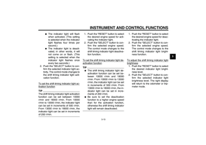 27
27 28
28 29
29 30
30 31
31 32
32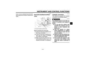 33
33 34
34 35
35 36
36 37
37 38
38 39
39 40
40 41
41 42
42 43
43 44
44 45
45 46
46 47
47 48
48 49
49 50
50 51
51 52
52 53
53 54
54 55
55 56
56 57
57 58
58 59
59 60
60 61
61 62
62 63
63 64
64 65
65 66
66 67
67 68
68 69
69 70
70 71
71 72
72 73
73 74
74 75
75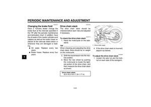 76
76 77
77 78
78 79
79 80
80 81
81 82
82 83
83 84
84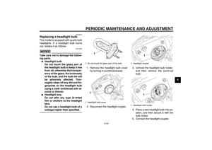 85
85 86
86 87
87 88
88 89
89 90
90 91
91 92
92 93
93 94
94 95
95 96
96 97
97 98
98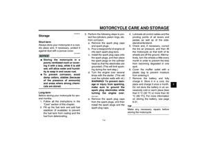 99
99 100
100 101
101 102
102 103
103 104
104 105
105 106
106 107
107
