2010 RENAULT SCENIC heating
[x] Cancel search: heatingPage 159 of 230

PETROL INJECTION
Fault finding - Conformity check
17B
17B-159
PETROL INJECTION
Fault finding - Conformity check
17B
17B-159V9 MR-372-J84-17B050$517.mif
S3000 Injection
Program No.: AD
Vdiag No.: 4C / 54
IGNITION/PREHEATING SUB-FUNCTION (continued 2):
NOTESOnly perform this conformity check after a complete check with the diagnostic tool.
The values shown in this conformity check are given as a guide.
Application conditions: Engine warm, idling.
Order FunctionParameter or Status Checked
or ActionDisplay and notes Fault finding
15
Combustion
misfire
GasET582:LPG combustion
misfire fault findingINACTIVEIn the event of a fault,
apply interpretation of
faults DF635
Combustion misfire
in LPG cylinder 1,
DF636 Combustion
misfire in LPG
cylinder 2, DF637
Combustion misfire
in LPG cylinder 3,
DF638 Combustion
misfire in LPG
cylinder 4. 16 ET583:LPG cylinder 1
combustion misfireNO
17 ET584:LPG cylinder 2
combustion misfireNO
18 ET585:LPG cylinder 3
combustion misfireNO
19 ET586:LPG cylinder 4
combustion misfireNO
20 Actuators AC079:Actuator static testAll the actuators
must be operated
(fuel pump relay,
electric coolant
pump on F4RT,
downstream and
upstream sensor
heating, motorised
throttle)In the event of a fault,
apply interpretation of
fault associated with
the actuators
concerned.
Page 163 of 230

PETROL INJECTION
Fault finding - Conformity check
17B
17B-163
PETROL INJECTION
Fault finding - Conformity check
17B
17B-163V9 MR-372-J84-17B050$517.mif
S3000 Injection
Program No.: AD
Vdiag No.: 4C / 54
HEATING SUB-FUNCTION:
OCR: Opening Cycle Ratio
NOTESOnly perform this conformity check after a complete check with the diagnostic tool.
The values shown in this conformity check are given as a guide.
Application conditions: Engine warm, idling.
Order FunctionParameter or Status
Checked or ActionDisplay and notes Fault finding
1Coolant
temperaturePR064:Coolant
temperature- 40°C < PR064 < 120°C
Safe value: - 39°CIn the event of a fault,
apply the
interpretation of
DF001 Coolant
temperature sensor
circuit.
2
Passenger
compartment
heating
resistorET111:RCH number setYES
NOIn the event of a
fault, run a multiplex
network test using
the diagnostic tool
then, if the test is in
order, consult the
Protection and
Switching Unit. 3ET112:RCH cut-offYES
NO
Page 168 of 230

PETROL INJECTION
Fault finding - Status summary table
17B
17B - 168
PETROL INJECTION
Fault finding - Status summary table
17B
17B - 168V9 MR-372-J84-17B050$564.mif
S3000 Injection
Program No.: AD
Vdiag No.: 4C / 54PETROL INJECTION
Fault finding - Status summary table
Tool status Diagnostic tool title
ET001+ After ignition computer feed
ET003Engine immobiliser
ET004Air conditioning authorisation
ET006Code programmed
ET021High speed fan assembly request
ET022Low speed fan assembly request
ET023Fast idle speed request
ET042Cruise control/speed limiter
ET047Fuel pump control circuit
ET048Actuator relay control
ET050Canister bleed control
ET051Throttle stop programming
ET052Upstream O
2 sensor heating
ET053Downstream O
2 sensor heating
ET054Idle speed regulation
ET056Richness double loop
ET057Misfiring on cylinder 1
ET058Misfiring on cylinder 2
ET059Misfiring on cylinder 3
ET060Misfiring on cylinder 4
ET061Cylinder 1 recognition
ET062Flywheel signal
ET063Park/Neutral position
ET064Level 1 injection fault
ET065Level 2 Injection fault
ET066LPG fault
ET067LPG ready
ET068LPG tank empty
ET071Transition from petrol mode to LPG mode
ET072Transition from LPG mode to petrol mode
ET073Conditions for switching to LPG mode
ET075Pedal released and throttle closed
MR-372-J84-17B050$564.mif
Page 175 of 230

PETROL INJECTION
Fault finding - Interpretation of statuses
17B
17B - 175
PETROL INJECTION
Fault finding - Interpretation of statuses
17B
17B - 175V9 MR-372-J84-17B050$611.mif
S3000 Injection
Program No.: AD
Vdiag No.: 4C / 54
ET056
DOUBLE RICHNESS LOOP
ACTIVE
INACTIVE
NOTESThere must be no present or stored faults.
Check the cleanliness and condition of the upstream oxygen sensor connections.
Repair if necessary.
Check for the + 12 V feed on track A of the upstream oxygen sensor connector with the ignition on.
If +12V is not present:
– disconnect the battery,
– check the cleanliness and condition of the connections.
Using the universal bornier, check the continuity on the following connection:
Injection computer, connectorB, track M2 track A of the upstream oxygen sensor
Protection and Communication Unit,
connector CT1, track 4
Repair if necessary.
Disconnect the battery and the injection computer.
Check the cleanliness and condition of the connections.
Using the Universal bornier, check the insulation and continuity of the following connections:
Injection computer connectorC, track C1 track D of the upstream oxygen sensor
Injection computer, connectorC, track B1 track C of the upstream oxygen sensor
Injection computer, connectorC, track L2 track B of the upstream oxygen sensor
Repair if necessary.
Measure the heating resistance of the upstream oxygen sensor between tracks A and B.
Replace the sensor if the resistance is not approximately 9Ω at 20°C.
Check the condition and secure fitting of the upstream oxygen sensor.
If the vehicle is driven frequently in town, carry out a decoking procedure.
AFTER REPAIRRepeat the conformity check from the start.
S3000_V4C_ET056/S3000_V54_ET056
Page 176 of 230

PETROL INJECTION
Fault finding - Interpretation of statuses
17B
17B - 176
PETROL INJECTION
Fault finding - Interpretation of statuses
17B
17B - 176V9 MR-372-J84-17B050$611.mif
S3000 Injection
Program No.: AD
Vdiag No.: 4C / 54
ET056
CONTINUED 1
Check the cleanliness and condition of the downstream oxygen sensor connections.
Repair if necessary.
Check for the + 12 V feed on track A of the downstream oxygen sensor connector with the ignition on.
If +12V is not present:
– disconnect the battery,
– check the cleanliness and condition of the connections.
Using the universal bornier, check the continuity on the following connection:
Injection computer, connectorB, track M2 track A of the downstream oxygen sensor
Protection and Communication Unit,
connector CT1, track 4
Repair if necessary.
Disconnect the battery and the injection computer.
Check the cleanliness and condition of the connections.
Using the Universal bornier, check the insulation and continuity of the following connections:
Injection computer, connectorC, track B2 track D of the downstream oxygen sensor
Injection computer, connectorC, track A2 track C of the downstream oxygen sensor
Injection computer, connectorC, track L3 track B of the downstream oxygen sensor
Repair if necessary.
Measure the heating resistance of the downstream oxygen sensor between tracks A and B.
Replace the sensor if the resistance is not approximately 9Ω at 20°C.
Check the condition and for secure fitting of the downstream oxygen sensor.
If the vehicle is normally driven in urban conditions, there is a risk of contamination of the oxygen sensor.
AFTER REPAIRRepeat the conformity check from the start.
Page 191 of 230

PETROL INJECTION
Fault finding - Interpretation of statuses
17B
17B - 191
PETROL INJECTION
Fault finding - Interpretation of statuses
17B
17B - 191V9 MR-372-J84-17B050$611.mif
S3000 Injection
Program No.: AD
Vdiag No.: 4C / 54
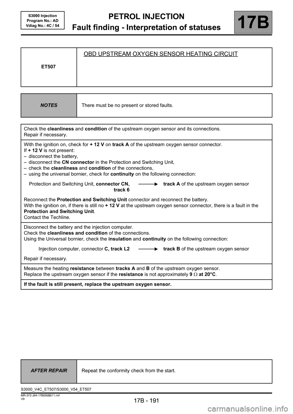
ET507
OBD UPSTREAM OXYGEN SENSOR HEATING CIRCUIT
NOTESThere must be no present or stored faults.
Check the cleanliness and condition of the upstream oxygen sensor and its connections.
Repair if necessary.
With the ignition on, check for + 12 V on track A of the upstream oxygen sensor connector.
If +12V is not present:
– disconnect the battery,
– disconnect the CN connector in the Protection and Switching Unit,
– check the cleanliness and condition of the connections,
– using the universal bornier, check for continuity on the following connection:
Protection and Switching Unit, connector CN,
track 6track A of the upstream oxygen sensor
Reconnect the Protection and Switching Unit connector and reconnect the battery.
With the ignition on, if there is still no +12V at the upstream oxygen sensor connector, there is a fault in the
Protection and Switching Unit.
Contact the Techline.
Disconnect the battery and the injection computer.
Check the cleanliness and condition of the connections.
Using the Universal bornier, check the insulation and continuity on the following connection:
Injection computer, connectorC, track L2 track B of the upstream oxygen sensor
Repair if necessary.
Measure the heating resistance between tracks A and B of the upstream oxygen sensor.
Replace the upstream oxygen sensor if the resistance is not approximately 9Ω at 20°C.
If the fault is still present, replace the upstream oxygen sensor.
AFTER REPAIRRepeat the conformity check from the start.
S3000_V4C_ET507/S3000_V54_ET507
Page 192 of 230

PETROL INJECTION
Fault finding - Interpretation of statuses
17B
17B - 192
PETROL INJECTION
Fault finding - Interpretation of statuses
17B
17B - 192V9 MR-372-J84-17B050$611.mif
S3000 Injection
Program No.: AD
Vdiag No.: 4C / 54
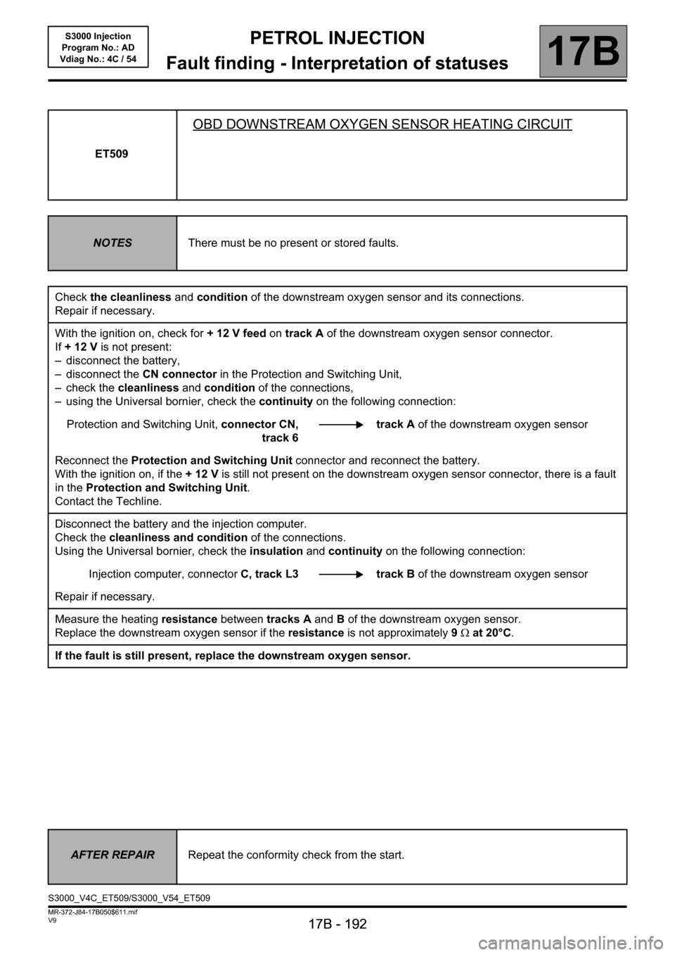
ET509
OBD DOWNSTREAM OXYGEN SENSOR HEATING CIRCUIT
NOTESThere must be no present or stored faults.
Check the cleanliness and condition of the downstream oxygen sensor and its connections.
Repair if necessary.
With the ignition on, check for + 12 V feed on track A of the downstream oxygen sensor connector.
If +12V is not present:
– disconnect the battery,
– disconnect the CN connector in the Protection and Switching Unit,
– check the cleanliness and condition of the connections,
– using the Universal bornier, check the continuity on the following connection:
Protection and Switching Unit, connector CN,
track 6track A of the downstream oxygen sensor
Reconnect the Protection and Switching Unit connector and reconnect the battery.
With the ignition on, if the +12V is still not present on the downstream oxygen sensor connector, there is a fault
in the Protection and Switching Unit.
Contact the Techline.
Disconnect the battery and the injection computer.
Check the cleanliness and condition of the connections.
Using the Universal bornier, check the insulation and continuity on the following connection:
Injection computer, connectorC, track L3 track B of the downstream oxygen sensor
Repair if necessary.
Measure the heating resistance between tracks A and B of the downstream oxygen sensor.
Replace the downstream oxygen sensor if the resistance is not approximately 9Ω at 20°C.
If the fault is still present, replace the downstream oxygen sensor.
AFTER REPAIRRepeat the conformity check from the start.
S3000_V4C_ET509/S3000_V54_ET509
Page 213 of 230

PETROL INJECTION
17B
17B-213
PETROL INJECTION
17B
17B-213V9 MR-372-J84-17B050$752.mif
S3000 Injection
Program No.: AD
Vdiag No.: 4C / 54PETROL INJECTION
Fault finding - Command summary table
Tool command Diagnostic tool title
RZ001Fault memory
RZ005Programming
AC017Canister bleed solenoid valve
AC018Upstream O
2 sensor heating
AC019Downstream O
2 sensor heating
AC027Motorised throttle
AC079Actuator static test
AC195Electric coolant pump
AC253Camshaft dephaser: Normal control
AC254Camshaft dephaser: ON/OFF control
VP020Enter VIN
MR-372-J84-17B050$752.mif