Page 180 of 230

PETROL INJECTION
Fault finding - Interpretation of statuses
17B
17B - 180
PETROL INJECTION
Fault finding - Interpretation of statuses
17B
17B - 180V9 MR-372-J84-17B050$611.mif
S3000 Injection
Program No.: AD
Vdiag No.: 4C / 54
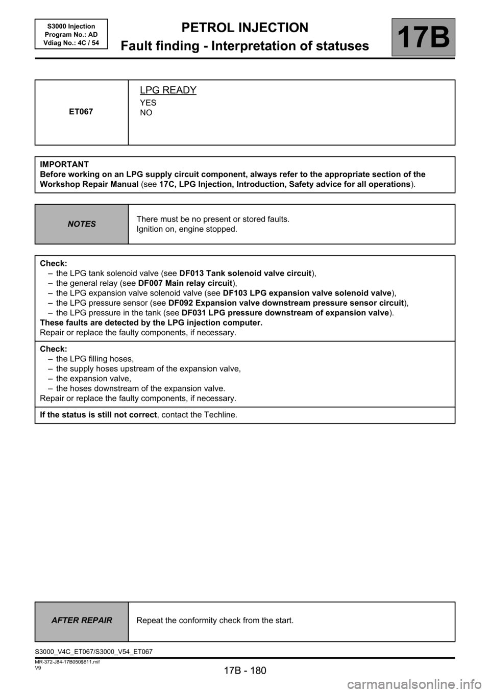
ET067
LPG READY
YES
NO
IMPORTANT
Before working on an LPG supply circuit component, always refer to the appropriate section of the
Workshop Repair Manual (see17C, LPG Injection, Introduction, Safety advice for all operations).
NOTESThere must be no present or stored faults.
Ignition on, engine stopped.
Check:
– the LPG tank solenoid valve (see DF013 Tank solenoid valve circuit),
– the general relay (see DF007 Main relay circuit),
– the LPG expansion valve solenoid valve (see DF103 LPG expansion valve solenoid valve),
– the LPG pressure sensor (see DF092 Expansion valve downstream pressure sensor circuit),
– the LPG pressure in the tank (see DF031 LPG pressure downstream of expansion valve).
These faults are detected by the LPG injection computer.
Repair or replace the faulty components, if necessary.
Check:
– the LPG filling hoses,
– the supply hoses upstream of the expansion valve,
– the expansion valve,
– the hoses downstream of the expansion valve.
Repair or replace the faulty components, if necessary.
If the status is still not correct, contact the Techline.
AFTER REPAIRRepeat the conformity check from the start.
S3000_V4C_ET067/S3000_V54_ET067
Page 182 of 230

PETROL INJECTION
Fault finding - Interpretation of statuses
17B
17B - 182
PETROL INJECTION
Fault finding - Interpretation of statuses
17B
17B - 182V9 MR-372-J84-17B050$611.mif
S3000 Injection
Program No.: AD
Vdiag No.: 4C / 54
ET071
TRANSITION FROM PETROL MODE TO LPG MODE
IN PROGRESS
COMPLETE
IMPORTANT
Before working on an LPG supply circuit component, always refer to the appropriate section of the
Workshop Repair Manual (see17C, LPG Injection, Introduction, Safety advice for all operations).
NOTESThere must be no present or stored faults.
Ignition on, engine stopped.
Special note:
The duration of the transition varies according to the outside temperature.
Check that the LPG tank solenoid valve clicks when LPG mode is entered.
If the LPG tank solenoid valve does not click, check:
– the LPG 10A fuse F15,
– the general relay (see DF007 Main relay circuit),
– the LPG tank solenoid valve wiring (see DF013 Solenoid valve tank circuit).
These faults are detected by the LPG injection computer.
Repair or replace the faulty components, if necessary.
If the status is still not correct, contact the Techline.
AFTER REPAIRRepeat the conformity check from the start.
S3000_V4C_ET071/S3000_V54_ET071
Page 184 of 230

PETROL INJECTION
Fault finding - Interpretation of statuses
17B
17B - 184
PETROL INJECTION
Fault finding - Interpretation of statuses
17B
17B - 184V9 MR-372-J84-17B050$611.mif
S3000 Injection
Program No.: AD
Vdiag No.: 4C / 54
ET073
CONDITIONS FOR SWITCHING TO LPG MODE
AUTHORISED
INHIBITED
IMPORTANT
Before working on an LPG supply circuit component, always refer to the appropriate section of the
Workshop Repair Manual (see17C, LPG Injection, Introduction, Safety advice for all operations).
NOTESThere must be no present or stored faults.
Ignition on, engine stopped.
Variable duration depending on:
–ET100 LPG system ready,
–PR002 Coolant temperature,
–PR103 Air temperature,
–PR113 LPG temperature.
Apply the interpretation of faults DF103 LPG expansion valve solenoid valve and DF007 Main relay circuit.
These faults are detected by the LPG injection computer.
Manipulate the wiring harness between the LPG computer and the petrol computer until a change in status is
noted.
Check the insulation, continuity and ensure the absence of interference resistance on the connections
between:
Petrol computer connectorB, track K3 track A1 of the LPG computer
Petrol computer connectorB, track K4 track A2 of the LPG computer
Repair if necessary.
If the status is still not correct, contact the Techline.
AFTER REPAIRRepeat the conformity check from the start.
S3000_V4C_ET073/S3000_V54_ET073