2010 NISSAN TIIDA Accelerator
[x] Cancel search: AcceleratorPage 59 of 3745

AT-42
< SERVICE INFORMATION >
TROUBLE DIAGNOSIS
TROUBLE DIAGNOSIS
DTC Inspection Priority ChartINFOID:0000000005397235
If some DTCs are displayed at the same time, perform inspections one by one based on the following priority
chart.
NOTE:
If DTC “CAN COMM CIRCUIT” is displayed with other DTCs, first perform the trouble diagnosis for
DTC “CAN COMM CIRCUIT”. Refer to AT- 8 7
.
Fail-SafeINFOID:0000000005397236
The TCM has an electronic Fail-safe mode. This allows t he vehicle to be driven even if a major electrical input/
output device circuit is damaged.
Under Fail-Safe, the vehicle always runs in 3GR, even wit h a shift lever position of “1”, “2” or “D”. The cus-
tomer may complain of sluggish or poor acceleration.
Always follow the “ AT-43, "
How to Perform Trouble Diagnosis for Quick and Accurate Repair" ”.
The SELF-DIAGNOSIS results will be as follows:
• The first SELF-DIAGNOSIS will indicate damage to the vehicle speed signal or the output speed sensor.
• During the next SELF-DIAGNOSIS, performed after checking the sensor, no damages will be indicated.
FAIL-SAFE FUNCTION
The following fail-safe functions allow vehicles to be driven even when sensor, switch or solenoid malfunction
occurs.
Output Speed Sensor
Vehicle speed signal is input from combination meter.
Accelerator Pedal Position Signal and Throttle Position Signal
TCM controls the throttle opening angle to a predetermined fixed position to enable driving if a malfunctioning
signal is input to TCM.
Transmission Range Switch
When the multiple transmission range switch signals are input to TCM, the priority of selector lever position
becomes “D”, “N”, “R”, “2” and “1” in order by internal TCM determination.
The use of 4GR is inhibited until normal operation resumes. Because the hydraulic circuit of the control valve
is switched by manual valve according to the selector lever position, however, actual operating condition of
vehicle becomes as follows.
Shift Solenoid Valve A and B
If non-standard solenoid signal is sent to TCM, use of certain gears is limited. Refer to chart shown below.
Priority Detected items
1 CAN communication line
2 Except above
Actual lever positionTransmission range switch input signal Running status
“P” “P” position and other position signals P
“R” “R” position and other position signals R
“N” “N” position and other position signals N
“D” “D” position and other position signals D
1 ⇔ D2 ⇔ D3 ⇔ D4
“2” “2” position and other position signals (Except “1” position)
21 ⇔ 22 ⇔ 23
“2” position and “1” position signals 21 ⇔ 22
“1” “1” position and other position signals (Except “2” position)
11 ⇔ 12 ⇔ 13
“1” position and “2” position signals 11 ⇔ 12
Revision: January 20102010 Versa
Page 66 of 3745
TROUBLE DIAGNOSISAT-49
< SERVICE INFORMATION >
DE
F
G H
I
J
K L
M A
B
AT
N
O P
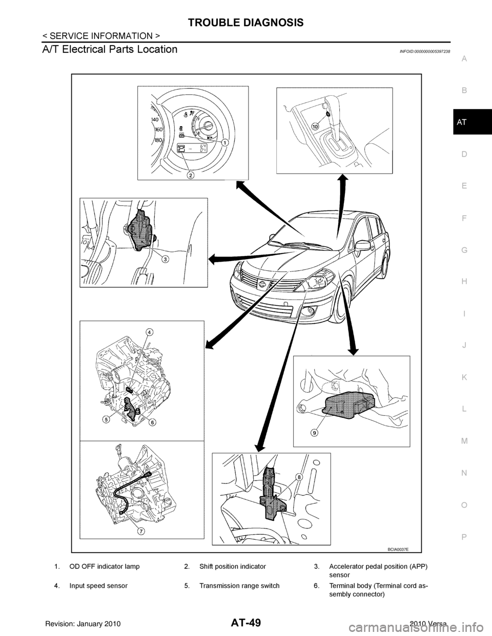
A/T Electrical Parts LocationINFOID:0000000005397238
1. OD OFF indicator lamp 2. Shift position indicator3. Accelerator pedal position (APP)
sensor
4. Input speed sensor 5. Transmission range switch6. Terminal body (Terminal cord as-
sembly connector)
BCIA0037E
Revision: January 20102010 Versa
Page 69 of 3745
AT-52
< SERVICE INFORMATION >
TROUBLE DIAGNOSIS
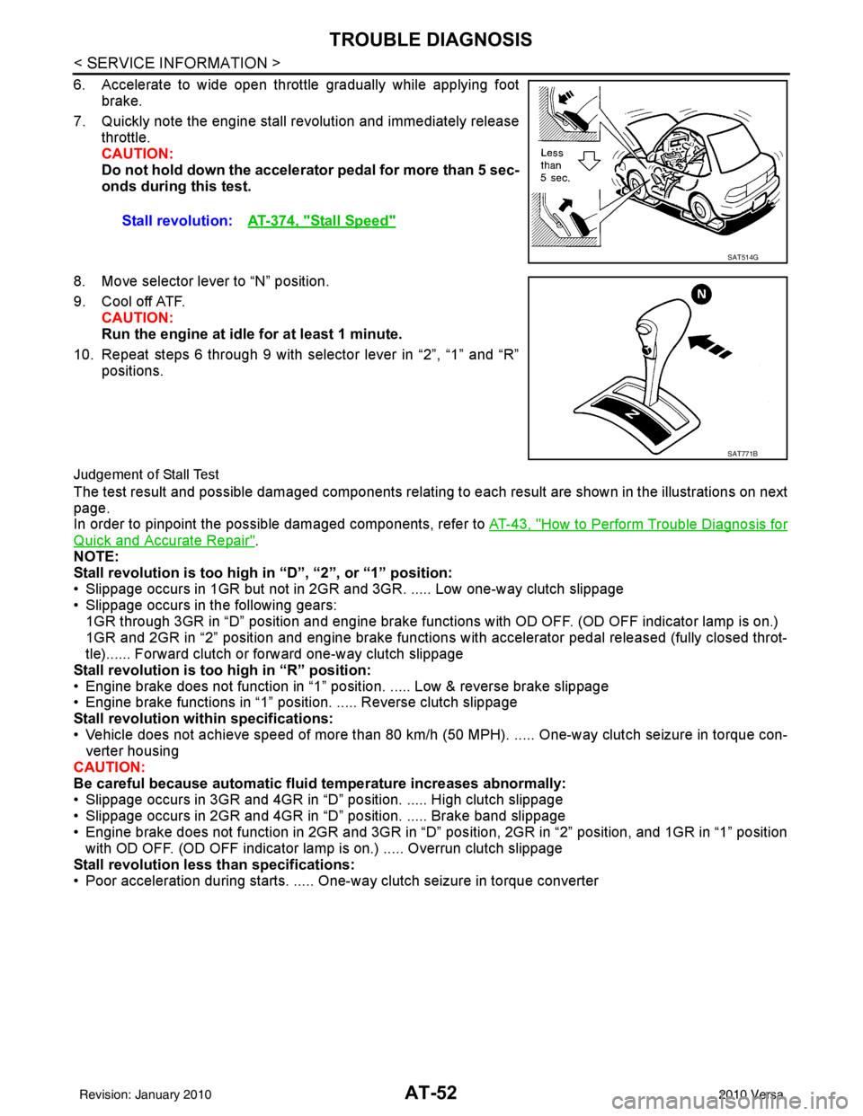
6. Accelerate to wide open throttle gradually while applying footbrake.
7. Quickly note the engine stall revolution and immediately release throttle.
CAUTION:
Do not hold down the accelerator pedal for more than 5 sec-
onds during this test.
8. Move selector lever to “N” position.
9. Cool off ATF. CAUTION:
Run the engine at idle for at least 1 minute.
10. Repeat steps 6 through 9 with selector lever in “2”, “1” and “R” positions.
Judgement of Stall Test
The test result and possible damaged components relating to each result are shown in the illustrations on next
page.
In order to pinpoint the possible damaged components, refer to AT-43, "
How to Perform Trouble Diagnosis for
Quick and Accurate Repair".
NOTE:
Stall revolution is too high in “D”, “2”, or “1” position:
• Slippage occurs in 1GR but not in 2GR and 3GR. ..... Low one-way clutch slippage
• Slippage occurs in the following gears:
1GR through 3GR in “D” position and engine brake functions with OD OFF. (OD OFF indicator lamp is on.)
1GR and 2GR in “2” position and engine brake functions with accelerator pedal released (fully closed throt-
tle)...... Forward clutch or forward one-way clutch slippage
Stall revolution is too high in “R” position:
• Engine brake does not function in “1” posit ion. ..... Low & reverse brake slippage
• Engine brake functions in “1” position. ..... Reverse clutch slippage
Stall revolution within specifications:
• Vehicle does not achieve speed of more than 80 km/h ( 50 MPH). ..... One-way clutch seizure in torque con-
verter housing
CAUTION:
Be careful because automatic flui d temperature increases abnormally:
• Slippage occurs in 3GR and 4GR in “D” position. ..... High clutch slippage
• Slippage occurs in 2GR and 4GR in “D” position. ..... Brake band slippage
• Engine brake does not function in 2GR and 3GR in “D” pos ition, 2GR in “2” position, and 1GR in “1” position
with OD OFF. (OD OFF indicator lamp is on.) ..... Overrun clutch slippage
Stall revolution less than specifications:
• Poor acceleration during starts. ..... One-way clutch seizure in torque converter Stall revolution:
AT-374, "
Stall Speed"
SAT514G
SAT771B
Revision: January 20102010 Versa
Page 72 of 3745
TROUBLE DIAGNOSISAT-55
< SERVICE INFORMATION >
DE
F
G H
I
J
K L
M A
B
AT
N
O P
Line Pressure
Judgement of Line Pressure Test
Road TestINFOID:0000000005397241
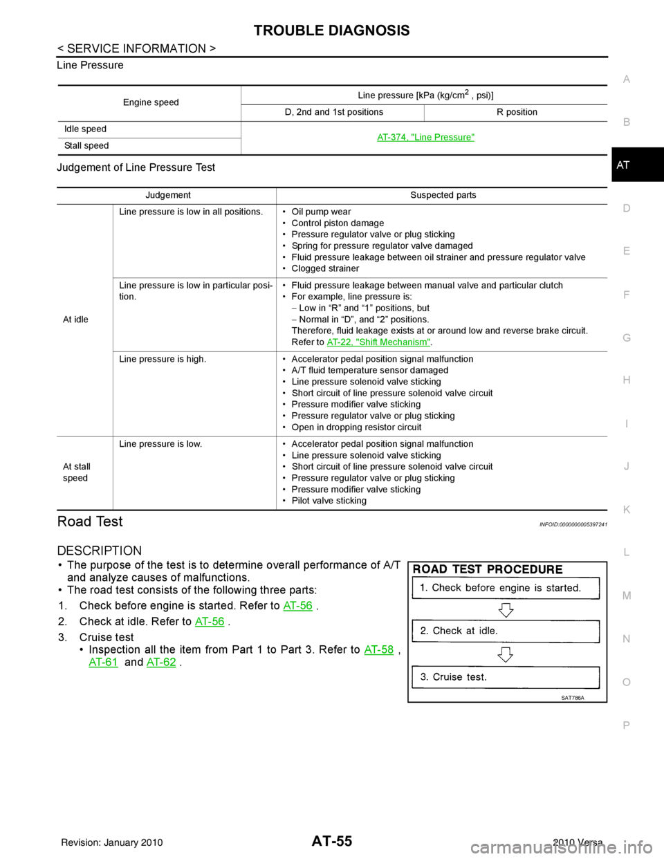
DESCRIPTION
• The purpose of the test is to det
ermine overall performance of A/T
and analyze causes of malfunctions.
• The road test consists of the following three parts:
1. Check before engine is started. Refer to AT- 5 6
.
2. Check at idle. Refer to AT- 5 6
.
3. Cruise test • Inspection all the item from Part 1 to Part 3. Refer to AT- 5 8
,
AT- 6 1
and AT- 6 2 .
Engine speed Line pressure [kPa (kg/cm
2 , psi)]
D, 2nd and 1st positions R position
Idle speed AT- 3 7 4 , "
Line Pressure"Sta ll sp ee d
JudgementSuspected parts
At idle Line pressure is low in all positions. • Oil pump wear
• Control piston damage
• Pressure regulator valve or plug sticking
• Spring for pressure regulator valve damaged
• Fluid pressure leakage between oil strainer and pressure regulator valve
• Clogged strainer
Line pressure is low in particular posi-
tion. • Fluid pressure leakage between manual valve and particular clutch
• For example, line pressure is:
− Low in “R” and “1 ” positions, but
− Normal in “D”, and “2” positions.
Therefore, fluid leakage exists at or around low and reverse brake circuit.
Refer to AT- 2 2 , "
Shift Mechanism".
Line pressure is high. • Accelerator pedal position signal malfunction
• A/T fluid temperature sensor damaged
• Line pressure solenoid valve sticking
• Short circuit of line pressure solenoid valve circuit
• Pressure modifier valve sticking
• Pressure regulator valve or plug sticking
• Open in dropping resistor circuit
At stall
speed Line pressure is low.
• Accelerator pedal position signal malfunction
• Line pressure solenoid valve sticking
• Short circuit of line pressure solenoid valve circuit
• Pressure regulator valve or plug sticking
• Pressure modifier valve sticking
• Pilot valve sticking
SAT786A
Revision: January 20102010 Versa
Page 76 of 3745
TROUBLE DIAGNOSISAT-59
< SERVICE INFORMATION >
DE
F
G H
I
J
K L
M A
B
AT
N
O P
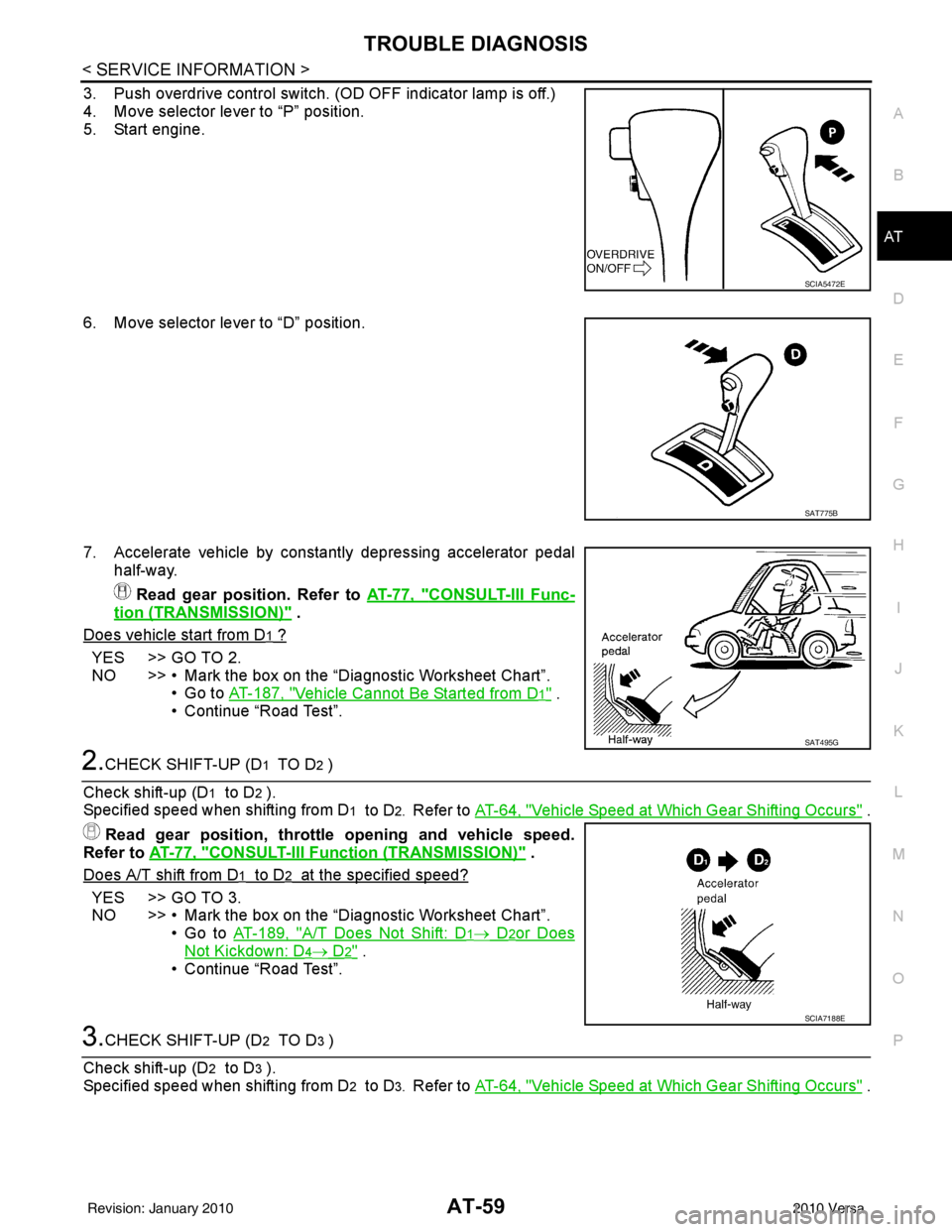
3. Push overdrive control switch. (OD OFF indicator lamp is off.)
4. Move selector lever to “P” position.
5. Start engine.
6. Move selector lever to “D” position.
7. Accelerate vehicle by constantly depressing accelerator pedal half-way.
Read gear position. Refer to AT-77, "
CONSULT-III Func-
tion (TRANSMISSION)" .
Does vehicle start from D
1 ?
YES >> GO TO 2.
NO >> • Mark the box on the “D iagnostic Worksheet Chart”.
•Go to AT-187, "
Vehicle Cannot Be Started from D1" .
• Continue “Road Test”.
2.CHECK SHIFT-UP (D1 TO D2 )
Check shift-up (D
1 to D2 ).
Specified speed when shifting from D
1 to D2. Refer to AT-64, "Vehicle Speed at Which Gear Shifting Occurs" .
Read gear position, throttle opening and vehicle speed.
Refer to AT-77, "
CONSULT-III Function (TRANSMISSION)" .
Does A/T shift from D
1 to D2 at the specified speed?
YES >> GO TO 3.
NO >> • Mark the box on the “D iagnostic Worksheet Chart”.
•Go to AT-189, "
A/T Does Not Shift: D1→ D2or Does
Not Kickdown: D4→ D2" .
• Continue “Road Test”.
3.CHECK SHIFT-UP (D2 TO D3 )
Check shift-up (D
2 to D3 ).
Specified speed when shifting from D
2 to D3. Refer to AT-64, "Vehicle Speed at Which Gear Shifting Occurs" .
SCIA5472E
SAT775B
SAT495G
SCIA7188E
Revision: January 20102010 Versa
Page 77 of 3745
AT-60
< SERVICE INFORMATION >
TROUBLE DIAGNOSIS
Read gear position, throttle opening and vehicle speed.
Refer to AT-77, "
CONSULT-III Function (TRANSMISSION)" .
Does A/T shift from D
2 to D3 at the specified speed?
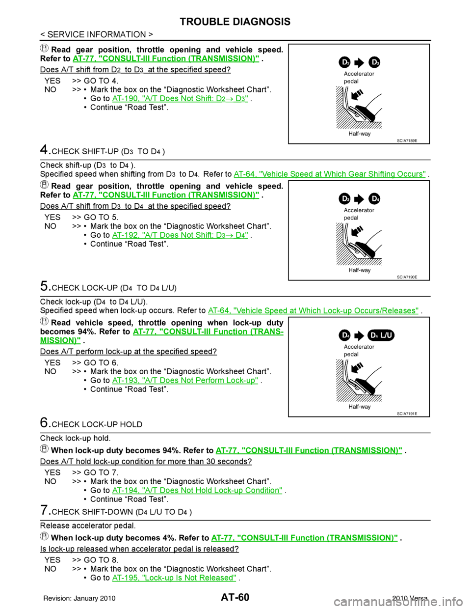
YES >> GO TO 4.
NO >> • Mark the box on the “Diagnostic Worksheet Chart”. •Go to AT-190, "
A/T Does Not Shift: D2→ D3" .
• Continue “Road Test”.
4.CHECK SHIFT-UP (D3 TO D4 )
Check shift-up (D
3 to D4 ).
Specified speed when shifting from D
3 to D4. Refer to AT-64, "Vehicle Speed at Which Gear Shifting Occurs" .
Read gear position, throttle opening and vehicle speed.
Refer to AT-77, "
CONSULT-III Function (TRANSMISSION)" .
Does A/T shift from D
3 to D4 at the specified speed?
YES >> GO TO 5.
NO >> • Mark the box on the “Diagnostic Worksheet Chart”. •Go to AT-192, "
A/T Does Not Shift: D3→ D4" .
• Continue “Road Test”.
5.CHECK LOCK-UP (D4 TO D4 L/U)
Check lock-up (D
4 to D4 L/U).
Specified speed when lock-up occurs. Refer to AT-64, "
Vehicle Speed at Which Lock-up Occurs/Releases" .
Read vehicle speed, throttle opening when lock-up duty
becomes 94%. Refer to AT-77, "
CONSULT-III Function (TRANS-
MISSION)" .
Does A/T perform lock-up at the specified speed?
YES >> GO TO 6.
NO >> • Mark the box on the “Diagnostic Worksheet Chart”.
•Go to AT-193, "
A/T Does Not Perform Lock-up" .
• Continue “Road Test”.
6.CHECK LOCK-UP HOLD
Check lock-up hold. When lock-up duty becomes 94%. Refer to AT-77, "
CONSULT-III Function (TRANSMISSION)" .
Does A/T hold lock-up condition for more than 30 seconds?
YES >> GO TO 7.
NO >> • Mark the box on the “Diagnostic Worksheet Chart”. •Go to AT-194, "
A/T Does Not Hold Lock-up Condition" .
• Continue “Road Test”.
7.CHECK SHIFT-DOWN (D4 L/U TO D4 )
Release accelerator pedal. When lock-up duty becomes 4%. Refer to AT-77, "
CONSULT-III Function (TRANSMISSION)" .
Is lock-up released when accelerator pedal is released?
YES >> GO TO 8.
NO >> • Mark the box on the “Diagnostic Worksheet Chart”. •Go to AT-195, "
Lock-up Is Not Released" .
SCIA7189E
SCIA7190E
SCIA7191E
Revision: January 20102010 Versa
Page 78 of 3745
TROUBLE DIAGNOSISAT-61
< SERVICE INFORMATION >
DE
F
G H
I
J
K L
M A
B
AT
N
O P
• Continue “Road Test”.
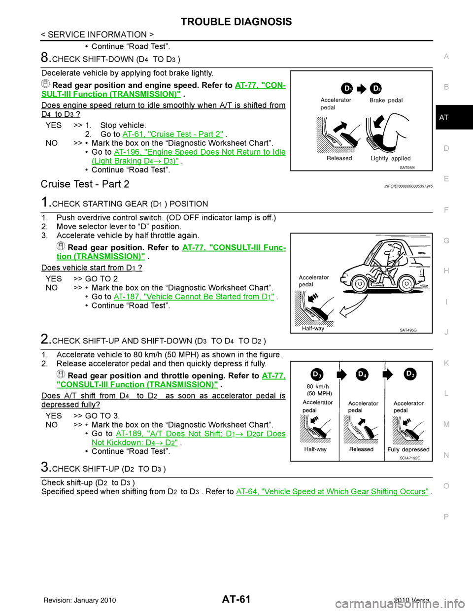
8.CHECK SHIFT-DOWN (D4 TO D3 )
Decelerate vehicle by applying foot brake lightly. Read gear position and engine speed. Refer to AT-77, "
CON-
SULT-III Function (TRANSMISSION)" .
Does engine speed return to idle smoothly when A/T is shifted from
D4 to D3 ?
YES >> 1. Stop vehicle. 2. Go to AT-61, "
Cruise Test - Part 2" .
NO >> • Mark the box on the “D iagnostic Worksheet Chart”.
•Go to AT-196, "
Engine Speed Does Not Return to Idle
(Light Braking D4→ D3)" .
• Continue “Road Test”.
Cruise Test - Part 2INFOID:0000000005397245
1.CHECK STARTING GEAR (D1 ) POSITION
1. Push overdrive control switch. (OD OFF indicator lamp is off.)
2. Move selector lever to “D” position.
3. Accelerate vehicle by half throttle again. Read gear position. Refer to AT-77, "
CONSULT-III Func-
tion (TRANSMISSION)" .
Does vehicle start from D
1 ?
YES >> GO TO 2.
NO >> • Mark the box on the “D iagnostic Worksheet Chart”.
•Go to AT-187, "
Vehicle Cannot Be Started from D1" .
• Continue “Road Test”.
2.CHECK SHIFT-UP AND SHIFT-DOWN (D3 TO D4 TO D2 )
1. Accelerate vehicle to 80 km/h (50 MPH) as shown in the figure.
2. Release accelerator pedal and then quickly depress it fully. Read gear position and th rottle opening. Refer to AT-77,
"CONSULT-III Function (TRANSMISSION)" .
Does A/T shift from D
4 to D2 as soon as accelerator pedal is
depressed fully?
YES >> GO TO 3.
NO >> • Mark the box on the “D iagnostic Worksheet Chart”.
•Go to AT-189, "
A/T Does Not Shift: D1→ D2or Does
Not Kickdown: D4→ D2" .
• Continue “Road Test”.
3.CHECK SHIFT-UP (D2 TO D3 )
Check shift-up (D
2 to D3 )
Specified speed when shifting from D
2 to D3 . Refer to AT-64, "Vehicle Speed at Which Gear Shifting Occurs" .
SAT959I
SAT495G
SCIA7192E
Revision: January 20102010 Versa
Page 79 of 3745
AT-62
< SERVICE INFORMATION >
TROUBLE DIAGNOSIS
Read gear position, throttle opening and vehicle speed.
Refer to AT-77, "
CONSULT-III Function (TRANSMISSION)" .
Does A/T shift from D
2 to D3 at the specified speed?
YES >> GO TO 4.
NO >> • Mark the box on the “Diagnostic Worksheet Chart”. •Go to AT-190, "
A/T Does Not Shift: D2→ D3" .
• Continue “Road Test”.
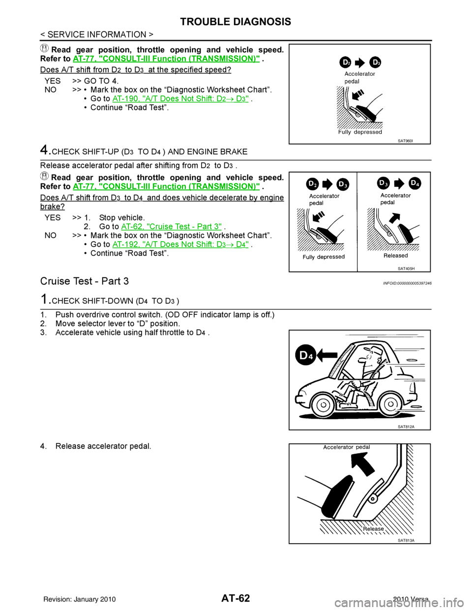
4.CHECK SHIFT-UP (D3 TO D4 ) AND ENGINE BRAKE
Release accelerator pedal after shifting from D
2 to D3 .
Read gear position, throttle opening and vehicle speed.
Refer to AT-77, "
CONSULT-III Function (TRANSMISSION)" .
Does A/T shift from D
3 to D4 and does vehicle decelerate by engine
brake?
YES >> 1. Stop vehicle. 2. Go to AT-62, "
Cruise Test - Part 3" .
NO >> • Mark the box on the “Diagnostic Worksheet Chart”.
•Go to AT-192, "
A/T Does Not Shift: D3→ D4" .
• Continue “Road Test”.
Cruise Test - Part 3INFOID:0000000005397246
1.CHECK SHIFT-DOWN (D4 TO D3 )
1. Push overdrive control switch. (OD OFF indicator lamp is off.)
2. Move selector lever to “D” position.
3. Accelerate vehicle using half throttle to D
4 .
4. Release accelerator pedal.
SAT960I
SAT405H
SAT812A
SAT813A
Revision: January 20102010 Versa