2010 NISSAN TIIDA Accelerator
[x] Cancel search: AcceleratorPage 1 of 3745

-1
QUICK REFERENCE INDEX
AGENERAL INFORMATIONGIGeneral Information
BENGINEEMEngine Mechanical
LUEngine Lubrication System
COEngine Cooling System
ECEngine Control System
FLFuel System
EXExhaust System
ACCAccelerator Control System
CTRANSMISSION/
TRANSAXLECLClutch System
MTManual Transaxle
ATAutomatic Transaxle
CVTCVT
DDRIVELINE/AXLEFAXFront Axle
RAXRear Axle
ESUSPENSIONFSUFront Suspension
RSURear Suspension
WTRoad Wheels & Tires
FBRAKESBRBrake System
PBParking Brake System
BRCBrake Control System
GSTEERINGPSPower Steering System
STCSteering Control System
HRESTRAINTSSBSeat Belts
SRSSupplemental Restraint System (SRS)
IBODYBLBody, Lock & Security System
GWGlasses, Window System & Mirrors
RFRoof
EIExterior & Interior
IPInstrument Panel
SESeat
JAIR CONDITIONERMTCManual Air Conditioner
KELECTRICALSCStarting & Charging System
LTLighting System
DIDriver Information System
WWWiper, Washer & Horn
BCSBody Control System
LANLAN System
AVAudio Visual, Navigation & Telephone System
ACSAuto Cruise Control System
PGPower Supply, Ground & Circuit Elements
LMAINTENANCEMAMaintenance
Edition: September 2009
Revision: January 2010
Publication No. SM0E-1C11U1
B
D
© 2010 NISSAN NORTH AMERICA, INC.
All rights reserved. No part of this Service Manual may be reproduced or stored in a retrieval system, or transmitted in any
form, or by any means, electronic, mechanical, photo-copying, recording or otherwise, without the prior written permission
of Nissan North America Inc.
A
C
E
F
G
H
I
J
K
L
M
Page 12 of 3745

ACC-1
ENGINE
C
DE
F
G H
I
J
K L
M
SECTION ACC
A
ACC
N
O P
CONTENTS
ACCELERATOR CONTROL SYSTEM
SERVICE INFORMATION .. ..........................2
PRECAUTIONS .............................................. .....2
Precaution for Supplemental Restraint System
(SRS) "AIR BAG" and "SEAT BELT PRE-TEN-
SIONER" ............................................................. ......
2
Precaution Necessary for Steering Wheel Rota-
tion After Battery Disconnect ............................... .....
2
ACCELERATOR CONTROL SYSTEM ..............4
Component ...............................................................4
Removal and Installation ..........................................4
Revision: January 20102010 Versa
Page 15 of 3745

ACC-4
< SERVICE INFORMATION >
ACCELERATOR CONTROL SYSTEM
ACCELERATOR CONTROL SYSTEM
ComponentINFOID:0000000005399823
Removal and InstallationINFOID:0000000005399824
CAUTION:
• Do not disassemble accelerator pedal assembly. Do not remove accelerator pedal position sensor
from accelerator pedal assembly.
• Avoid impact from dropping etc. during handling.
• Be careful to keep accelerator pedal assembly away from water.
REMOVAL
1. Disconnect the negative battery terminal.
2. Disconnect accelerator pedal position sensor harness connector.
3. Loosen mounting bolts, and remove accelerator pedal assembly.
INSTALLATION
Note the following, and install in the reverse order of removal.
• Insert locating pin into vehicle side to position accelerator pedal assembly. Install bolt to accelerator pedal assembly.
• Align the stud bolt on the floor with the thread hole to insert accelerator pedal stopper until it contacts the
face.
INSPECTION AFTER INSTALLATION
• Make sure that the accelerator pedal moves smoothly within the whole operation range.
• Make sure that the accelerator pedal securely returns to the original position.
• Perform accelerator pedal released position learning. Refer to EC-25, "
ACCELERATOR PEDAL
RELEASED POSITION LEARNING : Special Repair Requirement" (HR16DE), EC-580, "Accelerator Pedal
Released Position Learning" (MR18DE).
1. Accelerator pedal assembly 2. Locating pin 3. Accelerator pedal stopper
: Vehicle front
PBIC3813E
Revision: January 20102010 Versa
Page 47 of 3745
AT-30
< SERVICE INFORMATION >
A/T CONTROL SYSTEM
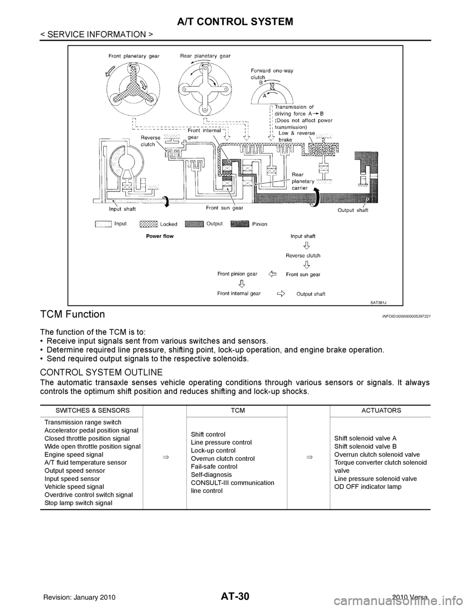
TCM Function
INFOID:0000000005397221
The function of the TCM is to:
• Receive input signals sent from various switches and sensors.
• Determine required line pressure, shifting poi nt, lock-up operation, and engine brake operation.
• Send required output signals to the respective solenoids.
CONTROL SYSTEM OUTLINE
The automatic transaxle senses vehicle operating conditions through various sensors or signals. It always
controls the optimum shift position and reduces shifting and lock-up shocks.
SAT381J
SWITCHES & SENSORS
⇒TCM
⇒ACTUATORS
Transmission range switch
Accelerator pedal position signal
Closed throttle position signal
Wide open throttle position signal
Engine speed signal
A/T fluid temperature sensor
Output speed sensor
Input speed sensor
Vehicle speed signal
Overdrive control switch signal
Stop lamp switch signal Shift control
Line pressure control
Lock-up control
Overrun clutch control
Fail-safe control
Self-diagnosis
CONSULT-III communication
line control
Shift solenoid valve A
Shift solenoid valve B
Overrun clutch solenoid valve
Torque converter clutch solenoid
valve
Line pressure solenoid valve
OD OFF indicator lamp
Revision: January 20102010 Versa
Page 48 of 3745
A/T CONTROL SYSTEMAT-31
< SERVICE INFORMATION >
DE
F
G H
I
J
K L
M A
B
AT
N
O P
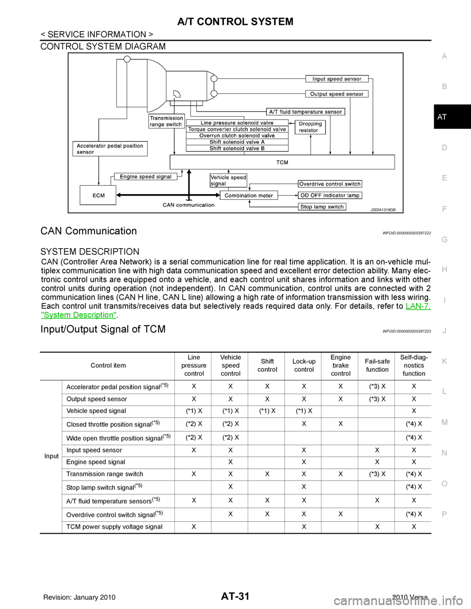
CONTROL SYSTEM DIAGRAM
CAN CommunicationINFOID:0000000005397222
SYSTEM DESCRIPTION
CAN (Controller Area Network) is a serial communication line for real time application. It is an on-vehicle mul-
tiplex communication line with high data communication speed and excellent error detection ability. Many elec-
tronic control units are equipped onto a vehicle, and each control unit shares information and links with other
control units during operation (not independent). In CAN communication, control units are connected with 2
communication lines (CAN H line, CAN L line) allowing a high rate of information transmission with less wiring.
Each control unit transmits/receives data but selectively reads required data only. For details, refer to LAN-7,
"System Description".
Input/Output Signal of TCMINFOID:0000000005397223
JSDIA1518GB
Control itemLine
pressure control Veh icl e
speed
control Shift
control Lock-up
control Engine
brake
control Fail-safe
function Self-diag-
nostics
function
Input Accelerator pedal position signal
(*5)XXXXX(*3) XX
Output speed sensor X X X X X (*3) X X
Vehicle speed signal (*1) X (*1) X (*1) X (*1) X X
Closed throttle position signal
(*5)(*2) X (*2) X X X(*4) X
Wide open throttle position signal
(*5)(*2) X (*2) X (*4) X
Input speed sensor X XXX X
Engine speed signal XXX X
Transmission range sw itch XXXXX(*3) X(*4) X
Stop lamp switch signal
(*5)XX ( *4 ) X
A/T fluid temperature sensors
(*5)XXXX XX
Overdrive control switch signal
(*5)XXXX (*4) X
TCM power supply voltage signal X XX X
Revision: January 20102010 Versa
Page 49 of 3745
AT-32
< SERVICE INFORMATION >
A/T CONTROL SYSTEM
*1: Output speed sensor
*2: Spare for accelerator pedal position signal
*3: If these input and output signals are different, the TCM triggers the fail-safe function.
*4: Used as a condition for starting self-diagnostics; if self-diagnosis are not started, it is judged that there is some kind of error.
*5: Input by CAN communications.
*6: Output by CAN communications.
Line Pressure ControlINFOID:0000000005397224
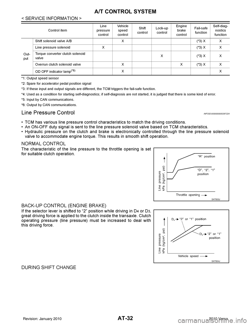
• TCM has various line pressure control char acteristics to match the driving conditions.
• An ON-OFF duty signal is sent to the line pres sure solenoid valve based on TCM characteristics.
• Hydraulic pressure on the clutch and brake is electronically controlled through the line pressure solenoid valve to accommodate engine torque. This results in smooth shift operation.
NORMAL CONTROL
The characteristic of the line pressure to the throttle opening is set
for suitable clutch operation.
BACK-UP CONTROL (ENGINE BRAKE)
If the selector lever is shifted to “2” position while driving in D4 or D3,
great driving force is applied to the clutch inside the transaxle. Clutch
operating pressure (line pressure) must be increased to deal with
this driving force.
DURING SHIFT CHANGE
Out-
put Shift solenoid valve A/B
X(*3) X X
Line pressure solenoid X (*3) X X
Torque converter clutch solenoid
valve X(
*3 ) X X
Overrun clutch solenoid valve XX (*3) X X
OD OFF indicator lamp
(*6)XX
Control item
Line
pressure
control Vehicle
speed
control Shift
control Lock-up
control Engine
brake
control Fail-safe
function Self-diag-
nostics
function
SAT003J
SAT004J
Revision: January 20102010 Versa
Page 50 of 3745
A/T CONTROL SYSTEMAT-33
< SERVICE INFORMATION >
DE
F
G H
I
J
K L
M A
B
AT
N
O P
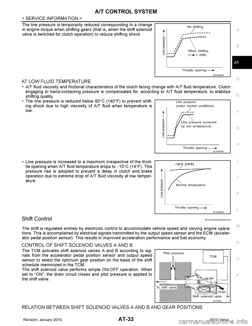
The line pressure is temporarily reduced corresponding to a change
in engine torque when shifting gears (that is, when the shift solenoid
valve is switched for clutch operation) to reduce shifting shock.
AT LOW FLUID TEMPERATURE
• A/T fluid viscosity and frictional characteristics of t he clutch facing change with A/T fluid temperature. Clutch
engaging or band-contacting pressure is compensated for, according to A/T fluid temperature, to stabilize
shifting quality.
• The line pressure is reduced below 60 °C (140° F) to prevent shift-
ing shock due to high viscosity of A/T fluid when temperature is
low.
• Line pressure is increased to a maximum irrespective of the throt- tle opening when A/T fluid temperature drops to −10° C (14° F). This
pressure rise is adopted to prevent a delay in clutch and brake
operation due to extreme drop of A/T fluid viscosity at low temper-
ature.
Shift ControlINFOID:0000000005397225
The shift is regulated entirely by electronic cont rol to accommodate vehicle speed and varying engine opera-
tions. This is accomplished by electrical signals trans mitted by the output speed sensor and the ECM (acceler-
ator pedal position sensor). This results in improved acceleration performance and fuel economy.
CONTROL OF SHIFT SOLENOID VALVES A AND B
The TCM activates shift solenoid valves A and B according to sig-
nals from the accelerator pedal position sensor and output speed
sensor to select the optimum gear position on the basis of the shift
schedule memorized in the TCM.
The shift solenoid valve performs simple ON-OFF operation. When
set to “ON”, the drain circuit closes and pilot pressure is applied to
the shift valve.
RELATION BETWEEN SHIFT SOLENOID VALVES A AND B AND GEAR POSITIONS
SCIA4828E
SCIA4829E
SCIA4830E
SAT008J
Revision: January 20102010 Versa
Page 51 of 3745
AT-34
< SERVICE INFORMATION >
A/T CONTROL SYSTEM
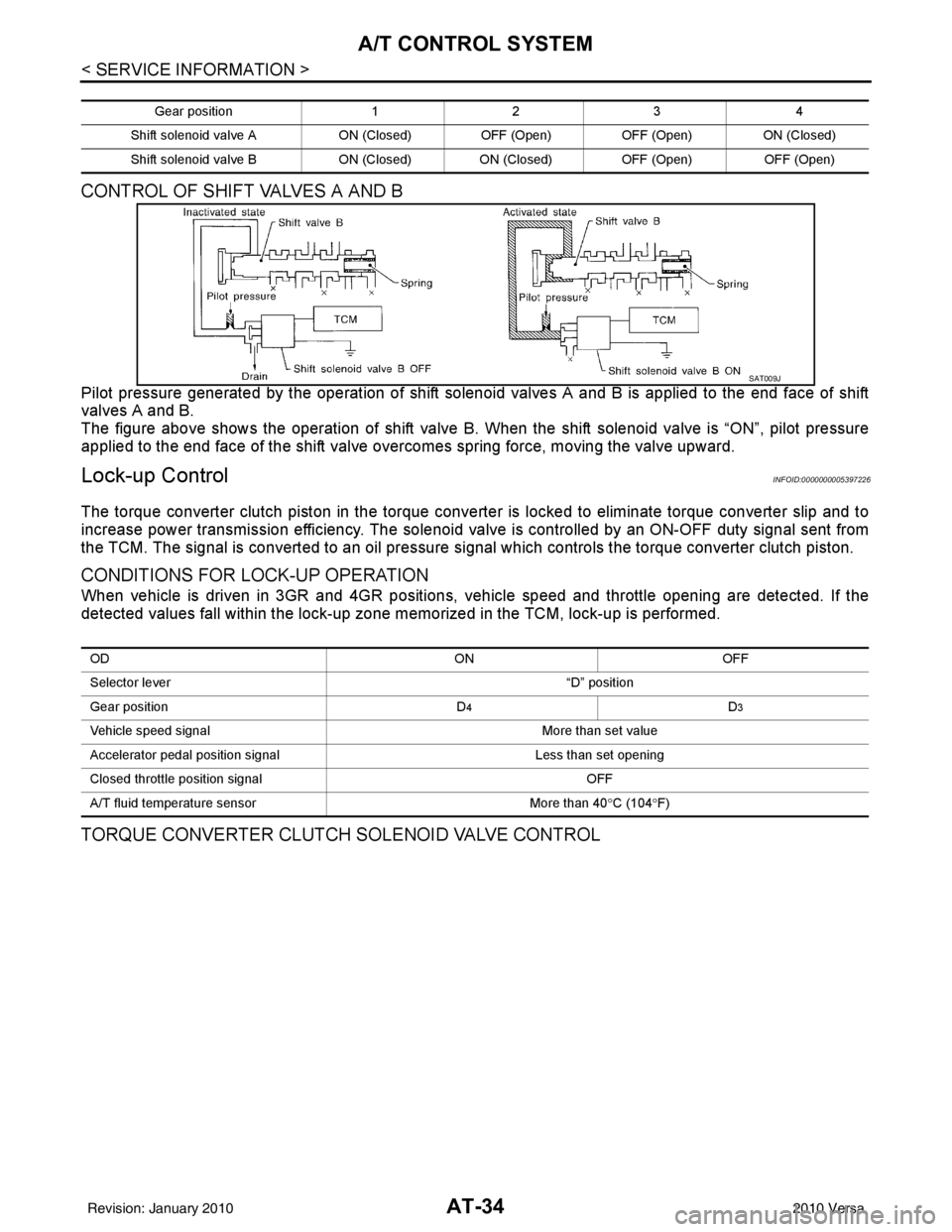
CONTROL OF SHIFT VALVES A AND B
Pilot pressure generated by the operation of shift solenoid valves A and B is applied to the end face of shift
valves A and B.
The figure above shows the operation of shift valve B. When the shift solenoid valve is “ON”, pilot pressure
applied to the end face of the shift valve overcomes spring force, moving the valve upward.
Lock-up ControlINFOID:0000000005397226
The torque converter clutch piston in the torque conver ter is locked to eliminate torque converter slip and to
increase power transmission efficiency. The solenoid va lve is controlled by an ON-OFF duty signal sent from
the TCM. The signal is converted to an oil pressure si gnal which controls the torque converter clutch piston.
CONDITIONS FOR LOCK-UP OPERATION
When vehicle is driven in 3GR and 4GR positions, v ehicle speed and throttle opening are detected. If the
detected values fall within the lock-up zone me morized in the TCM, lock-up is performed.
TORQUE CONVERTER CLUTCH SOLENOID VALVE CONTROL
Gear position123 4
Shift solenoid valve A ON (Closed)OFF (Open)OFF (Open) ON (Closed)
Shift solenoid valve B ON (Closed)ON (Closed) OFF (Open) OFF (Open)
SAT009J
OD ONOFF
Selector lever “D” position
Gear position D
4D3
Vehicle speed signal More than set value
Accelerator pedal position signal Less than set opening
Closed throttle position signal OFF
A/T fluid temperature sensor More than 40°C (104 °F)
Revision: January 20102010 Versa