2010 NISSAN TIIDA throttle
[x] Cancel search: throttlePage 20 of 3745

AT-3
DE
F
G H
I
J
K L
M A
B
AT
N
O
P
N
P1760 OVERRUN CLUTCH
SOLENOID .........148
Description .......................................................... ..148
CONSULT-III Reference Value in Data Monitor
Mode ................................................................... ..
148
On Board Diagnosis Logic ....................................148
Possible Cause .....................................................148
DTC Confirmation Procedure ................................148
Wiring Diagram - AT - OVRCSV ...........................149
Diagnosis Procedure .............................................150
Component Inspection ..........................................151
VEHICLE SPEED SIGNAL ...............................153
Description .......................................................... ..153
CONSULT-III Reference Value in Data Monitor
Mode ................................................................... ..
153
On Board Diagnosis Logic ....................................153
Possible Cause .....................................................153
DTC Confirmation Procedure ................................153
Wiring Diagram - AT - VSSMTR ...........................154
Diagnosis Procedure ........................................... ..155
BATT/FLUID TEMP SEN .................................156
Description .......................................................... ..156
CONSULT-III Reference Value in Data Monitor
Mode ................................................................... ..
156
On Board Diagnosis Logic ....................................156
Possible Cause .....................................................156
DTC Confirmation Procedure ................................156
Wiring Diagram - AT - BA/FTS ..............................157
Diagnosis Procedure .............................................158
Component Inspection ..........................................160
INPUT SPEED SENSOR A ..............................162
Description .......................................................... ..162
CONSULT-III Reference Value in Data Monitor
Mode ................................................................... ..
162
On Board Diagnosis Logic ....................................162
Possible Cause .....................................................162
DTC Confirmation Procedure ................................162
Wiring Diagram - AT - PT/SEN .............................163
Diagnosis Procedure .............................................164
CONTROL UNIT (RAM), CONTROL UNIT
(ROM) ...............................................................
167
Description .......................................................... ..167
On Board Diagnosis Logic ....................................167
Possible Cause .....................................................167
DTC Confirmation Procedure ................................167
Diagnosis Procedure .............................................167
MAIN POWER SUPPLY AND GROUND CIR-
CUIT ..................................................................
168
Wiring Diagram - AT - MAIN ............................... ..168
Diagnosis Procedure .............................................169
TR SW, OD SW AND CLOSED THROTTLE,
WIDE OPEN THROTTLE POSITION SIGNAL
CIRCUIT ......................................................... ..
171
CONSULT-III Reference Value in Data Monitor
Mode ................................................................... ..
171
TCM Terminal and Reference Value .....................171
Diagnosis Procedure ........................................... ..171
Component Inspection ...........................................175
SHIFT POSITION INDICATOR CIRCUIT ........176
Description .............................................................176
CONSULT-III Reference Value in Data Monitor
Mode .................................................................... ..
176
Diagnosis Procedure .............................................176
TROUBLE DIAGNOSIS FOR SYMPTOMS ....177
Wiring Diagram - AT - NONDTC ...........................177
OD OFF Indicator Lamp Does Not Come On ........180
Engine Cannot Be Started in "P" and "N" Position ..182
In "P" Position, Vehicle Moves Forward or Back-
ward When Pushed ...............................................
183
In "N" Position, Vehicle Moves ..............................183
Large Shock "N" → "R" Position .......................... ..184
Vehicle Does Not Creep Backward in "R" Position ..185
Vehicle Does Not Creep Forward in "D", "2" or "1"
Position ................................................................ ..
186
Vehicle Cannot Be Started from D1 .......................187
A/T Does Not Shift: D1→ D2or Does Not Kick-
down: D
4→ D2 ..................................................... ..189
A/T Does Not Shift: D2→ D3 ................................ ..190
A/T Does Not Shift: D3→ D4 ................................ ..192
A/T Does Not Perform Lock-up ........................... ..193
A/T Does Not Hold Lock-up Condition ...................194
Lock-up Is Not Released .......................................195
Engine Speed Does Not Return to Idle (Light
Braking D
4→ D3) ................................................. ..196
A/T Does Not Shift: D4→ D3, When OD OFF ...... ..197
A/T Does Not Shift: D3→ 22, When Selector Lever
"D" → "2" Position ............................................... ..
198
A/T Does Not Shift: 22→ 11, When Selector Lever
"2" → "1" Position ................................................ ..
199
Vehicle Does Not Decelerate by Engine Brake ... ..201
TCM Self-Diagnosis Does Not Activate .................204
A/T SHIFT LOCK SYSTEM .............................206
Description .............................................................206
Shift Lock System Parts Location ..........................207
Wiring Diagram - AT - SHIFT ................................208
Diagnosis Procedure .............................................208
TRANSMISSION CONTROL MODULE ..........212
Removal and Installation .......................................212
SHIFT CONTROL SYSTEM ............................213
A/T Shift Selector Removal and Installation ........ ..213
A/T Shift Selector Disassembly and Assembly ......216
Shift Lever Handle Removal and Installation .........216
Adjustment of A/T Position ....................................217
Checking of A/T Position .......................................217
KEY INTERLOCK CABLE ..............................219
Removal and Installation .......................................219
ON-VEHICLE SERVICE ..................................222
Control Valve Assembly and Accumulators ...........222
Revision: January 20102010 Versa
Page 41 of 3745
AT-24
< SERVICE INFORMATION >
A/T CONTROL SYSTEM
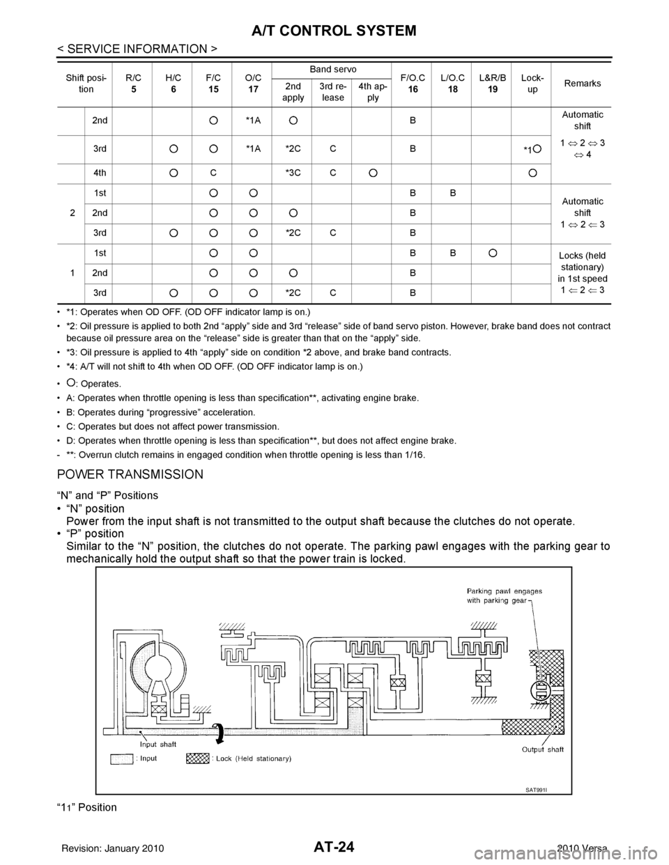
• *1: Operates when OD OFF. (OD OFF indicator lamp is on.)
• *2: Oil pressure is applied to both 2nd “apply” side and 3rd “release” side of band servo piston. However, brake band does not contract
because oil pressure area on the “release” side is greater than that on the “apply” side.
• *3: Oil pressure is applied to 4th “apply” side on condition *2 above, and brake band contracts.
• *4: A/T will not shift to 4th when OD OFF. (OD OFF indicator lamp is on.)
• : Operates.
• A: Operates when throttle opening is less than specification**, activating engine brake.
• B: Operates during “pro gressive” acceleration.
• C: Operates but does not affect power transmission.
• D: Operates when throttle opening is less than specification**, but does not affect engine brake.
- **: Overrun clutch remains in engaged condition when throttle opening is less than 1/16.
POWER TRANSMISSION
“N” and “P” Positions
• “N” position Power from the input shaft is not transmitted to the output shaft because the clutches do not operate.
• “P” position
Similar to the “N” position, the clutches do not operate. The parking pawl engages with the parking gear to
mechanically hold the output shaft so that the power train is locked.
“11” Position
2nd *1A BAutomatic
shift
3rd *1A *2C C B
*11
⇔ 2 ⇔ 3
⇔ 4
4th C*3C C
2 1st
BB
Automatic
shift
1 ⇔ 2 ⇐ 3
2nd
B
3rd *2C CB
1 1st
BB
Locks (held
stationary)
in 1st speed 1 ⇐ 2 ⇐ 3
2nd
B
3rd *2C CB
Shift posi-
tion R/C
5 H/C
6 F/C
15 O/C
17 Band servo
F/O.C
16 L/O.C
18 L&R/B
19 Lock-
up Remarks
2nd
apply 3rd re-
lease 4th ap-
ply
SAT991I
Revision: January 20102010 Versa
Page 42 of 3745
A/T CONTROL SYSTEMAT-25
< SERVICE INFORMATION >
DE
F
G H
I
J
K L
M A
B
AT
N
O P
“D
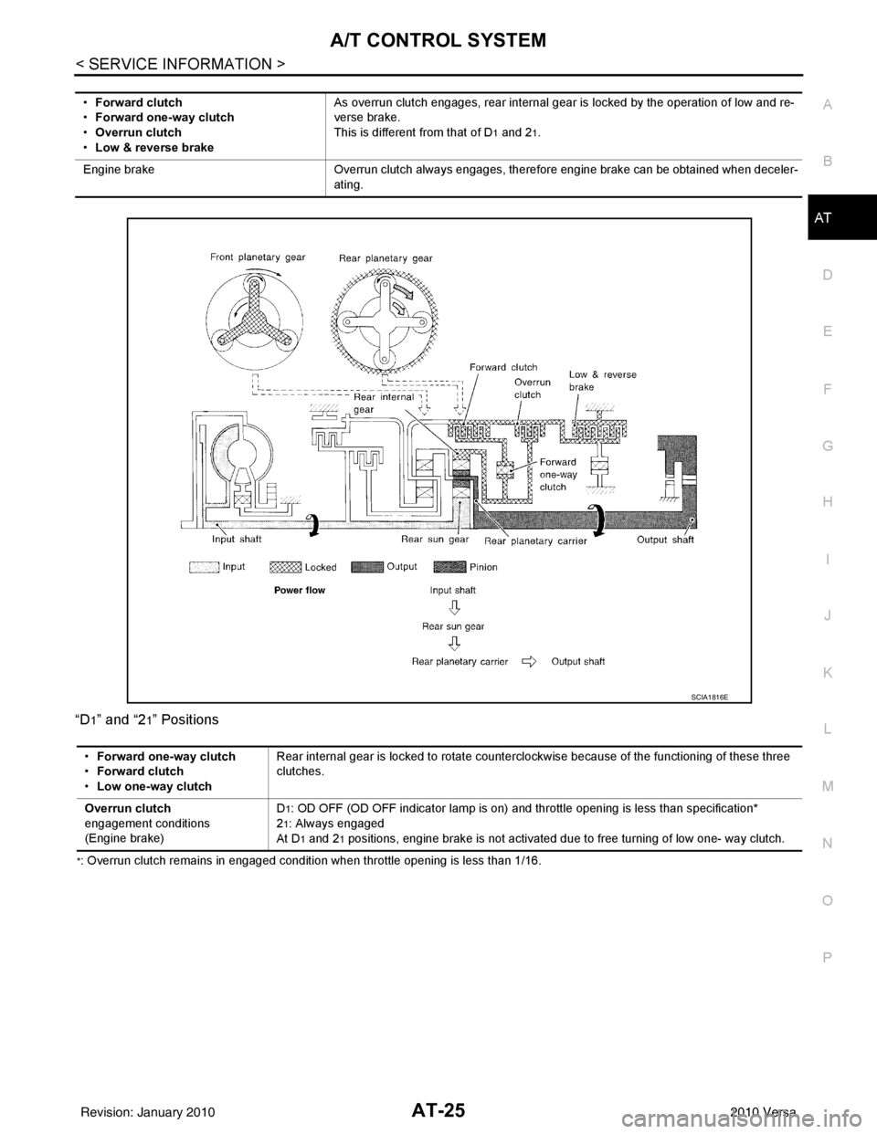
1” and “21” Positions
*: Overrun clutch remains in engaged condition when throttle opening is less than 1/16. •
Forward clutch
• Forward one-way clutch
• Overrun clutch
• Low & reverse brake As overrun clutch engages, rear internal gear is locked by the operation of low and re-
verse brake.
This is different from that of D
1 and 21.
Engine brake Overrun clutch always engages, therefore engine brake can be obtained when deceler-
ating.
SCIA1816E
• Forward one-way clutch
• Forward clutch
• Low one-way clutch Rear internal gear is locked to rotate counterclockwise because of the functioning of these three
clutches.
Overrun clutch
engagement conditions
(Engine brake) D
1: OD OFF (OD OFF indicator lamp is on) and th
rottle opening is less than specification*
2
1: Always engaged
At D
1 and 21 positions, engine brake is not activated due to free turning of low one- way clutch.
Revision: January 20102010 Versa
Page 43 of 3745
AT-26
< SERVICE INFORMATION >
A/T CONTROL SYSTEM
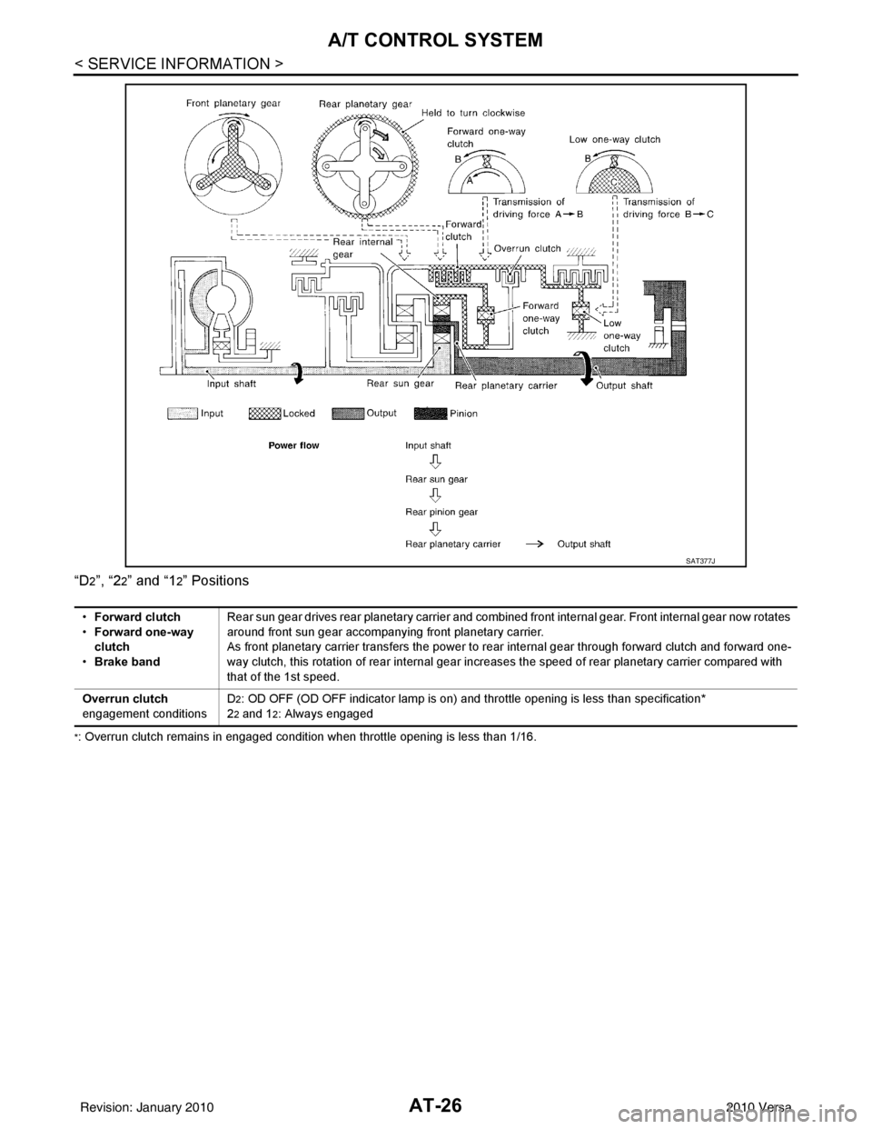
“D2”, “22” and “12” Positions
*: Overrun clutch remains in engaged condition when throttle opening is less than 1/16.
SAT377J
•Forward clutch
• Forward one-way
clutch
• Brake band Rear sun gear drives rear planetary carrier and combined front internal gear. Front internal gear now rotates
around front sun gear accompanying front planetary carrier.
As front planetary carrier transfers the power to rear internal gear through forward clutch and forward one-
way clutch, this rotation of rear internal gear increases the speed of rear planetary carrier compared with
that of the 1st speed.
Overrun clutch
engagement conditions D
2: OD OFF (OD OFF indicator lamp is on) and throttle opening is less than specification*
2
2 and 12: Always engaged
Revision: January 20102010 Versa
Page 44 of 3745
A/T CONTROL SYSTEMAT-27
< SERVICE INFORMATION >
DE
F
G H
I
J
K L
M A
B
AT
N
O P
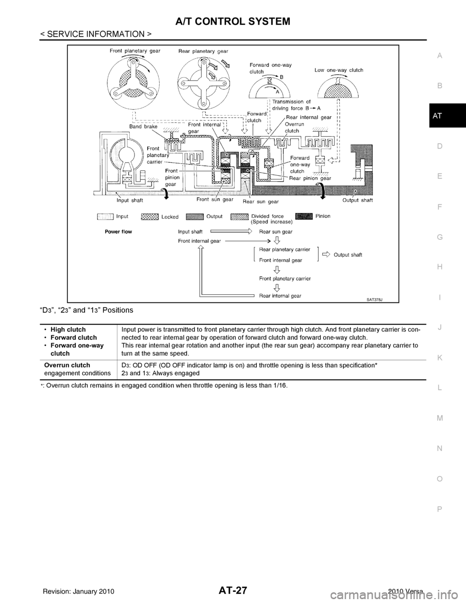
“D
3”, “23” and “13” Positions
*: Overrun clutch remains in engaged condition when throttle opening is less than 1/16.
SAT378J
•
High clutch
• Forward clutch
• Forward one-way
clutch Input power is transmitted to front planetary carrier through high clutch. And front planetary carrier is con-
nected to rear internal gear by operation of forward clutch and forward one-way clutch.
This rear internal gear rotation and another input (the rear sun gear) accompany rear planetary carrier to
turn at the same speed.
Overrun clutch
engagement conditions D
3: OD OFF (OD OFF indicator lamp is on) and throttle opening is less than specification*
2
3 and 13: Always engaged
Revision: January 20102010 Versa
Page 47 of 3745
AT-30
< SERVICE INFORMATION >
A/T CONTROL SYSTEM
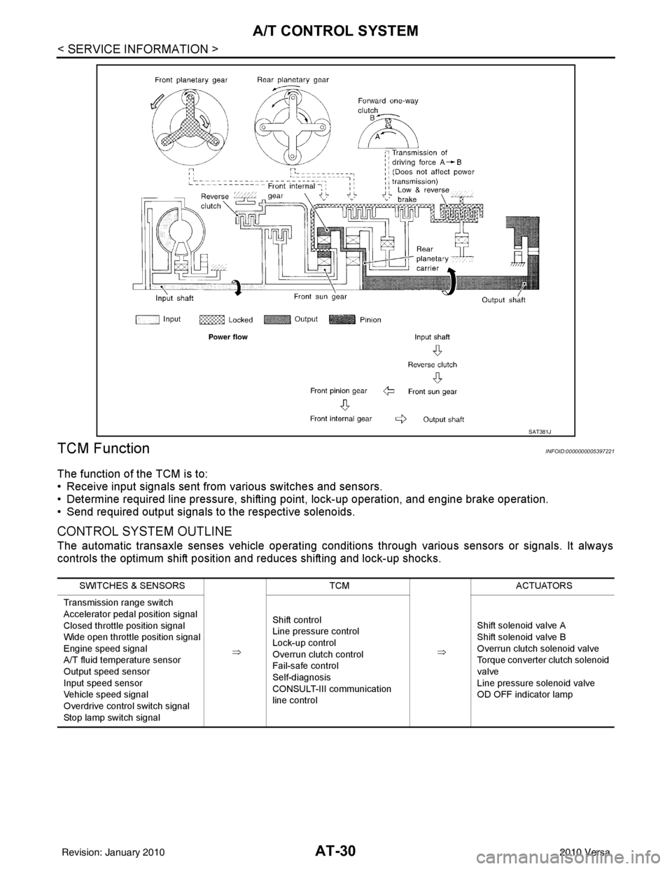
TCM Function
INFOID:0000000005397221
The function of the TCM is to:
• Receive input signals sent from various switches and sensors.
• Determine required line pressure, shifting poi nt, lock-up operation, and engine brake operation.
• Send required output signals to the respective solenoids.
CONTROL SYSTEM OUTLINE
The automatic transaxle senses vehicle operating conditions through various sensors or signals. It always
controls the optimum shift position and reduces shifting and lock-up shocks.
SAT381J
SWITCHES & SENSORS
⇒TCM
⇒ACTUATORS
Transmission range switch
Accelerator pedal position signal
Closed throttle position signal
Wide open throttle position signal
Engine speed signal
A/T fluid temperature sensor
Output speed sensor
Input speed sensor
Vehicle speed signal
Overdrive control switch signal
Stop lamp switch signal Shift control
Line pressure control
Lock-up control
Overrun clutch control
Fail-safe control
Self-diagnosis
CONSULT-III communication
line control
Shift solenoid valve A
Shift solenoid valve B
Overrun clutch solenoid valve
Torque converter clutch solenoid
valve
Line pressure solenoid valve
OD OFF indicator lamp
Revision: January 20102010 Versa
Page 48 of 3745
A/T CONTROL SYSTEMAT-31
< SERVICE INFORMATION >
DE
F
G H
I
J
K L
M A
B
AT
N
O P
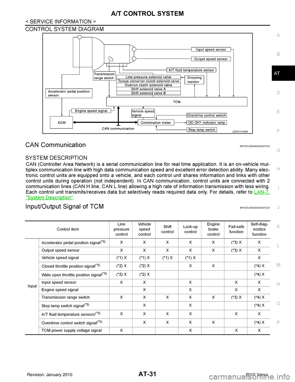
CONTROL SYSTEM DIAGRAM
CAN CommunicationINFOID:0000000005397222
SYSTEM DESCRIPTION
CAN (Controller Area Network) is a serial communication line for real time application. It is an on-vehicle mul-
tiplex communication line with high data communication speed and excellent error detection ability. Many elec-
tronic control units are equipped onto a vehicle, and each control unit shares information and links with other
control units during operation (not independent). In CAN communication, control units are connected with 2
communication lines (CAN H line, CAN L line) allowing a high rate of information transmission with less wiring.
Each control unit transmits/receives data but selectively reads required data only. For details, refer to LAN-7,
"System Description".
Input/Output Signal of TCMINFOID:0000000005397223
JSDIA1518GB
Control itemLine
pressure control Veh icl e
speed
control Shift
control Lock-up
control Engine
brake
control Fail-safe
function Self-diag-
nostics
function
Input Accelerator pedal position signal
(*5)XXXXX(*3) XX
Output speed sensor X X X X X (*3) X X
Vehicle speed signal (*1) X (*1) X (*1) X (*1) X X
Closed throttle position signal
(*5)(*2) X (*2) X X X(*4) X
Wide open throttle position signal
(*5)(*2) X (*2) X (*4) X
Input speed sensor X XXX X
Engine speed signal XXX X
Transmission range sw itch XXXXX(*3) X(*4) X
Stop lamp switch signal
(*5)XX ( *4 ) X
A/T fluid temperature sensors
(*5)XXXX XX
Overdrive control switch signal
(*5)XXXX (*4) X
TCM power supply voltage signal X XX X
Revision: January 20102010 Versa
Page 49 of 3745
AT-32
< SERVICE INFORMATION >
A/T CONTROL SYSTEM
*1: Output speed sensor
*2: Spare for accelerator pedal position signal
*3: If these input and output signals are different, the TCM triggers the fail-safe function.
*4: Used as a condition for starting self-diagnostics; if self-diagnosis are not started, it is judged that there is some kind of error.
*5: Input by CAN communications.
*6: Output by CAN communications.
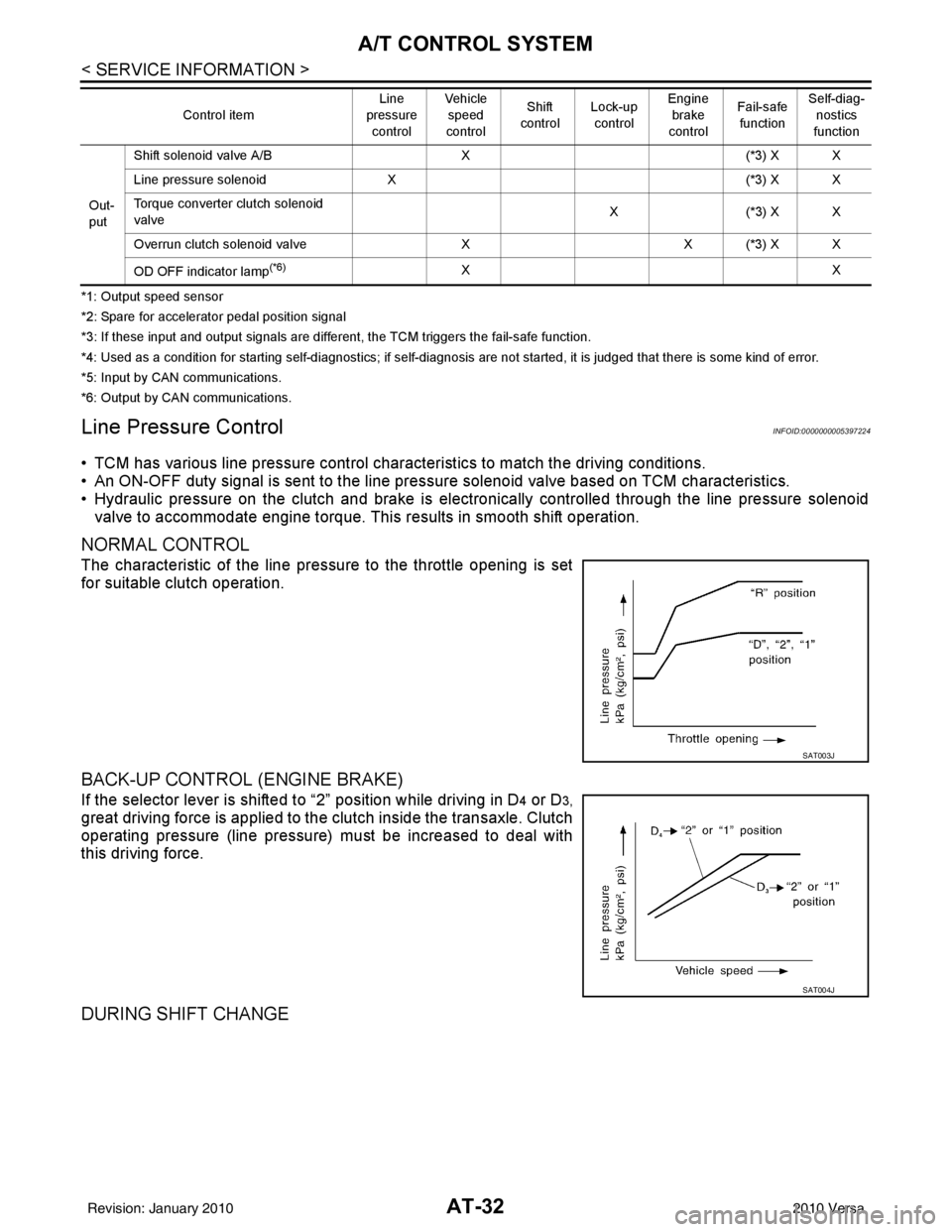
Line Pressure ControlINFOID:0000000005397224
• TCM has various line pressure control char acteristics to match the driving conditions.
• An ON-OFF duty signal is sent to the line pres sure solenoid valve based on TCM characteristics.
• Hydraulic pressure on the clutch and brake is electronically controlled through the line pressure solenoid valve to accommodate engine torque. This results in smooth shift operation.
NORMAL CONTROL
The characteristic of the line pressure to the throttle opening is set
for suitable clutch operation.
BACK-UP CONTROL (ENGINE BRAKE)
If the selector lever is shifted to “2” position while driving in D4 or D3,
great driving force is applied to the clutch inside the transaxle. Clutch
operating pressure (line pressure) must be increased to deal with
this driving force.
DURING SHIFT CHANGE
Out-
put Shift solenoid valve A/B
X(*3) X X
Line pressure solenoid X (*3) X X
Torque converter clutch solenoid
valve X(
*3 ) X X
Overrun clutch solenoid valve XX (*3) X X
OD OFF indicator lamp
(*6)XX
Control item
Line
pressure
control Vehicle
speed
control Shift
control Lock-up
control Engine
brake
control Fail-safe
function Self-diag-
nostics
function
SAT003J
SAT004J
Revision: January 20102010 Versa