2010 NISSAN TIIDA cvt transmission
[x] Cancel search: cvt transmissionPage 1 of 3745

-1
QUICK REFERENCE INDEX
AGENERAL INFORMATIONGIGeneral Information
BENGINEEMEngine Mechanical
LUEngine Lubrication System
COEngine Cooling System
ECEngine Control System
FLFuel System
EXExhaust System
ACCAccelerator Control System
CTRANSMISSION/
TRANSAXLECLClutch System
MTManual Transaxle
ATAutomatic Transaxle
CVTCVT
DDRIVELINE/AXLEFAXFront Axle
RAXRear Axle
ESUSPENSIONFSUFront Suspension
RSURear Suspension
WTRoad Wheels & Tires
FBRAKESBRBrake System
PBParking Brake System
BRCBrake Control System
GSTEERINGPSPower Steering System
STCSteering Control System
HRESTRAINTSSBSeat Belts
SRSSupplemental Restraint System (SRS)
IBODYBLBody, Lock & Security System
GWGlasses, Window System & Mirrors
RFRoof
EIExterior & Interior
IPInstrument Panel
SESeat
JAIR CONDITIONERMTCManual Air Conditioner
KELECTRICALSCStarting & Charging System
LTLighting System
DIDriver Information System
WWWiper, Washer & Horn
BCSBody Control System
LANLAN System
AVAudio Visual, Navigation & Telephone System
ACSAuto Cruise Control System
PGPower Supply, Ground & Circuit Elements
LMAINTENANCEMAMaintenance
Edition: September 2009
Revision: January 2010
Publication No. SM0E-1C11U1
B
D
© 2010 NISSAN NORTH AMERICA, INC.
All rights reserved. No part of this Service Manual may be reproduced or stored in a retrieval system, or transmitted in any
form, or by any means, electronic, mechanical, photo-copying, recording or otherwise, without the prior written permission
of Nissan North America Inc.
A
C
E
F
G
H
I
J
K
L
M
Page 597 of 3745
BL-88
< SERVICE INFORMATION >
INTELLIGENT KEY SYSTEM
System Description
INFOID:0000000005396599
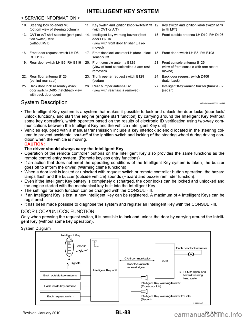
• The Intelligent Key system is a system that makes it possible to lock and unlock the door locks (door lock/
unlock function), and start the engine (engine start func tion) by carrying around the Intelligent Key (without
some key operation), which operates based on the results of electronic ID verification using two-way com-
munications between the Intelligent Key and the vehicle (Intelligent Key unit).
• Vehicles equipped with a manual transmission include a key interlock solenoid located in the steering col- umn to prevent accidental shut-off of the ignition sw itch and locking of the steering wheel during driving con-
dition when the vehicle is moving.
CAUTION:
The driver should always carry the Intelligent Key
• Operation of the remote controller buttons on the Inte lligent Key also provides the same functions as the
remote control entry system. (Remote keyless entry functions)
• If an action that does not meet the operating conditions of the Intelligent Key system is taken, the buzzer
goes off to inform the driver. (Warning chime functions)
• When a door lock is locked or unlocked with request switch or remote controller button operation, the hazard
lamps flash and the buzzer (outside vehicle) sounds (Hazard and buzzer reminder function).
• Even if the Intelligent Key battery is completely discharged, the door locks can be locked and unlocked and the engine started with the mechanical key built into the Intelligent Key.
• The settings for each function can be changed with the CONSULT-III.
• If an Intelligent Key is lost, a new Intelligent Key can be registered. A maximum of 4 Intelligent Keys can be registered.
• It has been made possible to diagnose the system and r egister an Intelligent Key with the CONSULT-III.
DOOR LOCK/UNLOCK FUNCTION
Only when pressing the request switch, it is possible to lock and unlock the door by carrying around the Intelli-
gent Key (without some key operation).
System Diagram
10. Steering lock solenoid M6
(bottom view of steering column) 11. Key switch and ignition knob switch M73
(with CVT or A/T) 12. Key switch and ignition knob switch M73
(with M/T)
13. CVT or A/T shift selector (park posi- tion switch) M38
(without M/T) 14. Intelligent key warning buzzer (front
door LH) D6
(view with front door finisher LH re-
moved) 15. Front outside antenna LH D10, RH D106
16. Front door request switch LH D5, RH D103 17. Front door lock actuator LH (door unlock
sensor) D3 18. Front door switch LH B8, RH B108
19. Rear door switch LH B6, RH B116 20. Front console antenna B125 (view of front console without arm rest
removed)21. Front console antenna B125
(view of front console with arm rest re-
moved)
22. Rear floor antenna B126 (behind rear seat) 23. Trunk opener request switch B129
(sedan) 24. Back door request switch D406
(hatchback)
25. Back door lock assembly (back door switch) D405 (hatchback view
with back door open) 26. Rear bumper antenna B2
(view with rear fascia removed) 27. Intelligent Key warn
ing buzzer (trunk) B32
(sedan)
LIIA2926E
Revision: January 20102010 Versa
Page 619 of 3745
BL-110
< SERVICE INFORMATION >
INTELLIGENT KEY SYSTEM
*1: With continuously variable transmission (CVT) or automatic transmission (A/T).
*2: With manual transmission (M/T).
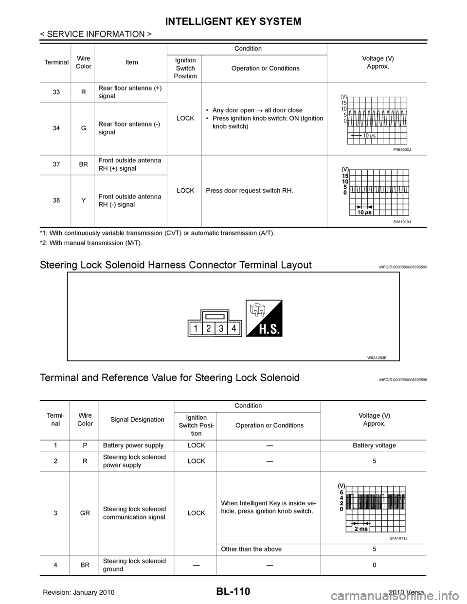
Steering Lock Solenoid Harn ess Connector Terminal LayoutINFOID:0000000005396605
Terminal and Reference Valu e for Steering Lock SolenoidINFOID:0000000005396606
33 RRear floor antenna (+)
signal
LOCK• Any door open
→ all door close
• Press ignition knob switch: ON (Ignition knob switch)
34 G Rear floor antenna (-)
signal
37 BR Front outside antenna
RH (+) signal
LOCK Press door request switch RH.
38 Y Front outside antenna
RH (-) signal
Te r m i n a l
Wire
Color Item Condition
Voltage (V)Approx.
Ignition
Switch
Position Operation or Conditions
PIIB5502J
SIIA1910J
WIIA1283E
Te r m i -
nal Wire
Color Signal Designation Condition
Voltage (V)Approx.
Ignition
Switch Posi- tion Operation or Conditions
1 P Battery power supply LOCK —Battery voltage
2R Steering lock solenoid
power supply LOCK
— 5
3GR Steering lock solenoid
communication signal
LOCKWhen Intelligent Key is inside ve-
hicle, press ignition knob switch.
Other than the above
5
4BR Steering lock solenoid
ground ——
0
SIIA1911J
Revision: January 20102010 Versa
Page 690 of 3745
BACK DOOR LOCKBL-181
< SERVICE INFORMATION >
C
DE
F
G H
J
K L
M A
B
BL
N
O P
*1: With continuously variable transmission (CVT) or automatic transmission (A/T).
*2: With manual transmission (M/T).
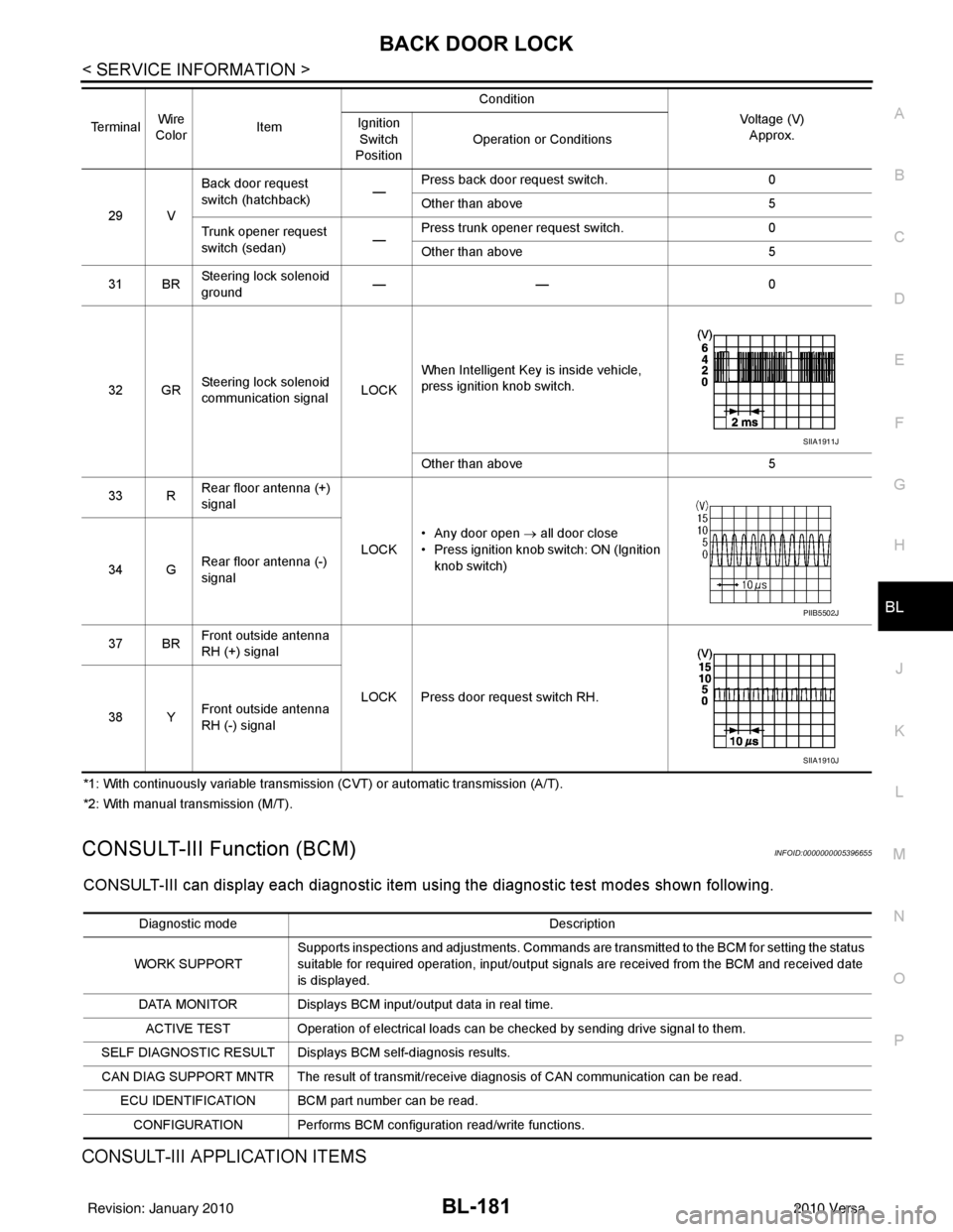
CONSULT-III Function (BCM)INFOID:0000000005396655
CONSULT-III can display each diagnostic item using the diagnostic test modes shown following.
CONSULT-III APPLICATION ITEMS
29 V Back door request
switch (hatchback)
—Press back door request switch.
0
Other than above 5
Trunk opener request
switch (sedan) —Press trunk opener request switch.
0
Other than above 5
31 BR Steering lock solenoid
ground ——
0
32 GR Steering lock solenoid
communication signal LOCKWhen Intelligent Key is inside vehicle,
press ignition knob switch.
Other than above
5
33 R Rear floor antenna (+)
signal
LOCK• Any door open
→ all door close
• Press ignition knob switch: ON (Ignition
knob switch)
34 G Rear floor antenna (-)
signal
37 BR Front outside antenna
RH (+) signal
LOCK Press door request switch RH.
38 Y Front outside antenna
RH (-) signal
Terminal
Wire
Color Item Condition
Voltage (V)Approx.
Ignition
Switch
Position Operation or Conditions
SIIA1911J
PIIB5502J
SIIA1910J
Diagnostic mode
Description
WORK SUPPORT Supports inspections and adjustments. Commands are transmitted to the BCM for setting the status
suitable for required operation, input/output signals are received from the BCM and received date
is displayed.
DATA MONITOR Displays BCM input/output data in real time. ACTIVE TEST Operation of electrical loads can be checked by sending drive signal to them.
SELF DIAGNOSTIC RESULT Displays BCM self-diagnosis results.
CAN DIAG SUPPORT MNTR The result of transmit/receive diagnosis of CAN communication can be read. ECU IDENTIFICATION BCM part number can be read.CONFIGURATION Performs BCM configuration read/write functions.
Revision: January 20102010 Versa
Page 714 of 3745
TRUNK LID OPENERBL-205
< SERVICE INFORMATION >
C
DE
F
G H
J
K L
M A
B
BL
N
O P
*1: With continuously variable transmission (CVT) or automatic transmission (A/T).
*2: With manual transmission (M/T).
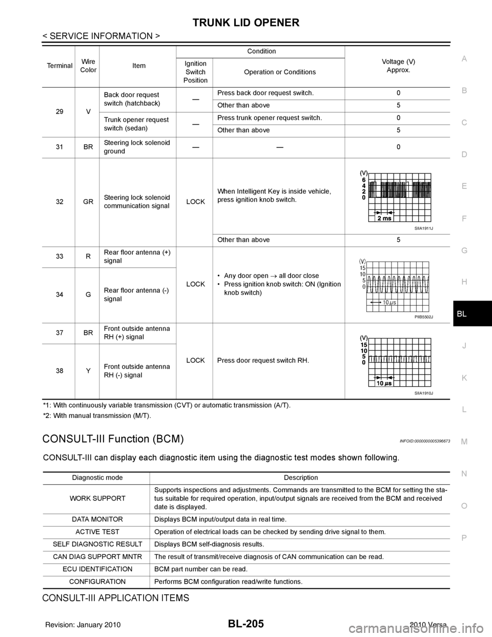
CONSULT-III Function (BCM)INFOID:0000000005396673
CONSULT-III can display each diagnostic item using the diagnostic test modes shown following.
CONSULT-III APPLICATION ITEMS
29 V Back door request
switch (hatchback)
—Press back door request switch.
0
Other than above 5
Trunk opener request
switch (sedan) —Press trunk opener request switch.
0
Other than above 5
31 BR Steering lock solenoid
ground ——
0
32 GR Steering lock solenoid
communication signal LOCKWhen Intelligent Key is inside vehicle,
press ignition knob switch.
Other than above
5
33 R Rear floor antenna (+)
signal
LOCK• Any door open
→ all door close
• Press ignition knob switch: ON (Ignition
knob switch)
34 G Rear floor antenna (-)
signal
37 BR Front outside antenna
RH (+) signal
LOCK Press door request switch RH.
38 Y Front outside antenna
RH (-) signal
Terminal
Wire
Color Item Condition
Voltage (V)Approx.
Ignition
Switch
Position Operation or Conditions
SIIA1911J
PIIB5502J
SIIA1910J
Diagnostic mode
Description
WORK SUPPORT Supports inspections and adjustments. Commands are transmitted to the BCM for setting the sta-
tus suitable for required operation, input/output signals are received from the BCM and received
date is displayed.
DATA MONITOR Displays BCM input/output data in real time. ACTIVE TEST Operation of electrical loads can be checked by sending drive signal to them.
SELF DIAGNOSTIC RESULT Displays BCM self-diagnosis results.
CAN DIAG SUPPORT MNTR The result of transmit/receive diagnosis of CAN communication can be read. ECU IDENTIFICATION BCM part number can be read.CONFIGURATION Performs BCM configuration read/write functions.
Revision: January 20102010 Versa
Page 742 of 3745
VEHICLE SECURITY (THEFT WARNING) SYSTEMBL-233
< SERVICE INFORMATION >
C
DE
F
G H
J
K L
M A
B
BL
N
O P
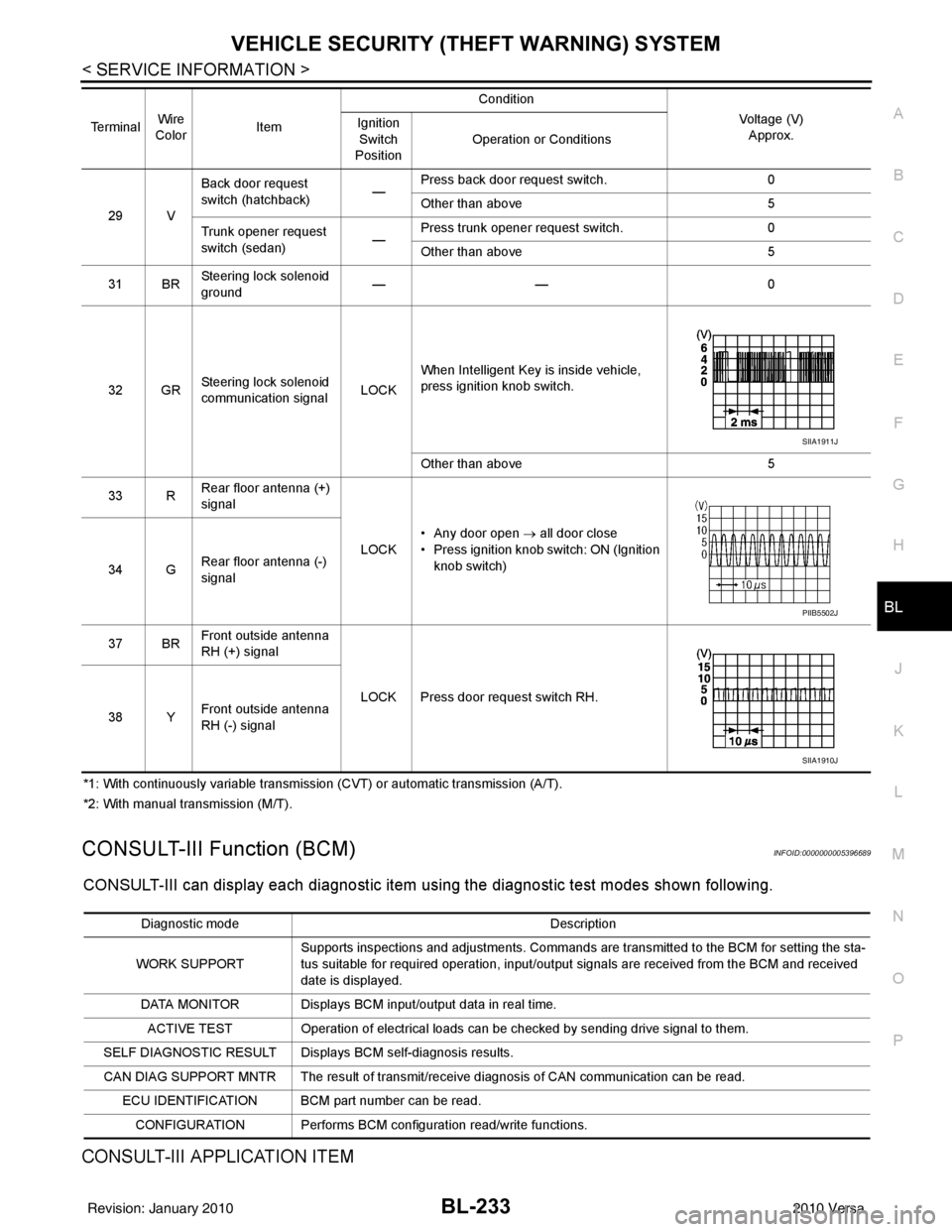
*1: With continuously variable transmission (CVT) or automatic transmission (A/T).
*2: With manual transmission (M/T).
CONSULT-III Function (BCM)INFOID:0000000005396689
CONSULT-III can display each diagnostic item using the diagnostic test modes shown following.
CONSULT-III APPLICATION ITEM
29 V Back door request
switch (hatchback)
—Press back door request switch.
0
Other than above 5
Trunk opener request
switch (sedan) —Press trunk opener request switch.
0
Other than above 5
31 BR Steering lock solenoid
ground ——
0
32 GR Steering lock solenoid
communication signal LOCKWhen Intelligent Key is inside vehicle,
press ignition knob switch.
Other than above
5
33 R Rear floor antenna (+)
signal
LOCK• Any door open
→ all door close
• Press ignition knob switch: ON (Ignition
knob switch)
34 G Rear floor antenna (-)
signal
37 BR Front outside antenna
RH (+) signal
LOCK Press door request switch RH.
38 Y Front outside antenna
RH (-) signal
Terminal
Wire
Color Item Condition
Voltage (V)Approx.
Ignition
Switch
Position Operation or Conditions
SIIA1911J
PIIB5502J
SIIA1910J
Diagnostic mode
Description
WORK SUPPORT Supports inspections and adjustments. Commands are transmitted to the BCM for setting the sta-
tus suitable for required operation, input/output signals are received from the BCM and received
date is displayed.
DATA MONITOR Displays BCM input/output data in real time. ACTIVE TEST Operation of electrical loads can be checked by sending drive signal to them.
SELF DIAGNOSTIC RESULT Displays BCM self-diagnosis results.
CAN DIAG SUPPORT MNTR The result of transmit/receive diagnosis of CAN communication can be read. ECU IDENTIFICATION BCM part number can be read.CONFIGURATION Performs BCM configuration read/write functions.
Revision: January 20102010 Versa
Page 969 of 3745
![NISSAN TIIDA 2010 Service Repair Manual TROUBLE DIAGNOSIS FOR SELF-DIAGNOSTIC ITEMS
BRC-79
< SERVICE INFORMATION > [VDC/TCS/ABS]
C
D
E
G H
I
J
K L
M A
B
BRC
N
O P
Check the self-diagnosis results.
Is the above displayed in the self-diagnosi NISSAN TIIDA 2010 Service Repair Manual TROUBLE DIAGNOSIS FOR SELF-DIAGNOSTIC ITEMS
BRC-79
< SERVICE INFORMATION > [VDC/TCS/ABS]
C
D
E
G H
I
J
K L
M A
B
BRC
N
O P
Check the self-diagnosis results.
Is the above displayed in the self-diagnosi](/manual-img/5/57397/w960_57397-968.png)
TROUBLE DIAGNOSIS FOR SELF-DIAGNOSTIC ITEMS
BRC-79
< SERVICE INFORMATION > [VDC/TCS/ABS]
C
D
E
G H
I
J
K L
M A
B
BRC
N
O P
Check the self-diagnosis results.
Is the above displayed in the self-diagnosis display items?
YES >> GO TO 2.
NO >> Inspection End.
2.CONNECTOR INSPECTION
1. Disconnect the ABS actuator and el ectric unit (control unit) and brake fluid level switch connectors.
2. Check the terminals for deformation, disconnection, looseness or damage.
OK or NG
OK >> GO TO 3.
NG >> Repair or replace as necessary.
3.CHECK TRANSMISSION RANGE SWITCH
Perform transmission range switch inspection. Refer to AT-94, "
Component Inspection" (with A/T) or CVT-65,
"Component Inspection" (with CVT).
Is the inspection result normal?
YES >> Replace ABS actuator and electr ic unit (control unit). Refer to BRC-89, "Removal and Installa-
tion".
NO >> Repair or replace malfunctioning components.
CAN Communication System InspectionINFOID:0000000005612171
INSPECTION PROCEDURE
1.SELF-DIAGNOSIS RESULT CHECK
Check the self-diagnosis results.
Is the above displayed in the self-diagnosis display items?
YES >> GO TO 2.
NO >> Inspection End.
2.CHECK CONNECTOR
1. Disconnect the ABS actuator and electric unit (control unit) connector, and check the terminals for defor- mation, disconnection, looseness, and so on. If there is a malfunction, repair or replace the terminals.
2. Reconnect connector to perform self-diagnosis. Refer to BRC-60, "
CONSULT-III Function (ABS)".
Is
“CAN COMM CIRCUIT” displayed in the self-diagnosis display items?
YES >> Refer to LAN-17, "Trouble Diagnosis Flow Chart".
NO >> Connector terminal connection is loose, damaged, open, or shorted.
Component InspectionINFOID:0000000005612172
VDC OFF SWITCH
Self-diagnosis results
PNP POS SIG
Self-diagnosis results
ST ANG SEN COM CIR CAN COMM CIRCUIT
Revision: January 20102010 Versa
Page 1034 of 3745

CVT-1
TRANSMISSION/TRANSAXLE
DE
F
G H
I
J
K L
M
SECTION CVT
A
B
CVT
N
O P
CONTENTS
CVT
RE0F08B
SERVICE INFORMATION .. ..........................
5
INDEX FOR DTC ............................................ .....5
Alphabetical Index ............................................... ......5
DTC No. Index ..........................................................5
PRECAUTIONS ...................................................7
Precaution for Supplemental Restraint System
(SRS) "AIR BAG" and "SEAT BELT PRE-TEN-
SIONER" ............................................................. ......
7
Precaution Necessary for Steering Wheel Rota-
tion After Battery Disconnect ............................... ......
7
Precaution for On Board Diagnosis (OBD) System
of CVT and Engine ....................................................
8
Service After Replacing TCM and Transaxle As-
sembly .......................................................................
8
Removal and Installation Procedure for CVT Unit
Connector ............................................................ ......
9
Precaution ...............................................................10
Service Notice or Precaution ...................................11
ATFTEMP COUNT Conversion Table ....................11
PREPARATION .............................................. ....13
Special Service Tool ........................................... ....13
Commercial Service Tool ........................................13
CVT FLUID .........................................................14
Checking CVT Fluid ............................................ ....14
Changing CVT Fluid ................................................15
CVT Fluid Cooler Cleaning .....................................15
CVT SYSTEM ................................................. ....19
Cross-Sectional View - RE0F08B ....................... ....19
Control System .................................................... ....20
Hydraulic Control System ........................................21
TCM Function ...................................................... ....21
CAN Communication ...............................................22
Input/Output Signal of TCM .....................................22
Line Pressure and Secondary Pressure Control .....23
Shift Control ............................................................23
Lock-up and Select Control .....................................25
Control Valve ....................................................... ....25
ON BOARD DIAGNOSTIC (OBD) SYSTEM ....27
Introduction ..............................................................27
OBD-II Function for CVT System ............................27
One or Two Trip Detection Logic of OBD-II .............27
OBD-II Diagnostic Trouble Code (DTC) ..................27
Malfunction Indicator Lamp (MIL) ............................28
TROUBLE DIAGNOSIS ....................................30
DTC Inspection Priority Chart ..................................30
Fail-Safe ..................................................................30
How to Perform Trouble Diagnosis for Quick and
Accurate Repair .......................................................
31
CVT Electrical Parts Location ..................................36
Circuit Diagram ........................................................37
Inspections before Trouble Diagnosis .....................37
Road Test ................................................................41
Check before Engine Is Started ...............................42
Check at Idle ............................................................42
Cruise Test ..............................................................43
Vehicle Speed When Shifting Gears .......................45
TCM Terminal and Reference Value .......................46
CONSULT-III Function (TRANSMISSION) .......... ....48
Diagnosis Procedure without CONSULT-III ............55
U1000 CAN COMM CIRCUIT ...........................56
Description ........................................................... ....56
On Board Diagnosis Logic .......................................56
Possible Cause ........................................................56
DTC Confirmation Procedure ..................................56
Wiring Diagram - CVT - CAN ...................................57
Diagnosis Procedure ...............................................58
U1010 CONTROL UNIT (CAN) .........................59
Description ...............................................................59
On Board Diagnosis Logic .......................................59
Possible Cause ........................................................59
DTC Confirmation Procedure ..................................59
Diagnosis Procedure ...............................................59
Revision: January 20102010 Versa