2010 NISSAN TIIDA cvt transmission
[x] Cancel search: cvt transmissionPage 3148 of 3745

PERIODIC MAINTENANCEMA-13
< SERVICE INFORMATION >
C
DE
F
G H
I
J
K
M A
B
MA
N
O P
(1) Using transmission fluid other than Genuine NISSAN CVT Flui d NS-2 will damage the CVT, which is not covered by the
NISSAN new vehicle limited warranty .
(2) Refer to “Tire rotation” under the “GENERAL MAINTENANCE” heading earlier in this section.
Exhaust system I I
EX-5
HR16DE,
EX-11
MR18DE
In-cabin microfilter RR RRMA-37
MAINTENANCE OPERATION MAINTENANCE INTERVAL
Reference Sec-
tion - Page or -
Content Title
Perform at number of miles, kilo-
meters or months, whichever
comes first. Miles x 1,000
(km x 1,000)
Months 7.5
(12)
6 15
(24)
12 22.5
(36)
18 30
(48)
24 37.5
(60)
30 45
(72)
36 52.5
(84)
42 60
(96)
48
Revision: January 20102010 Versa
Page 3149 of 3745

MA-14
< SERVICE INFORMATION >
RECOMMENDED FLUIDS AND LUBRICANTS
RECOMMENDED FLUIDS AND LUBRICANTS
Fluids and LubricantsINFOID:0000000005394798
*1: For further details, see “Engine Oil Recommendation”.
*2: If genuine NISSAN gear oil is not available, API GL-4, Viscosity SAE 75W-80 may be used as a temporary replacement. However
use Genuine NISSAN gear oil as soon as it is possible.
*3: Using transaxle fluid other than Genuine NISSAN CVT Fluid NS-2 will damage the CVT, which is not covered by the NISSAN
new vehicle limited warranty.
*4: Available in mainland U.S.A. through a NISSAN dealer.
*5: For further details, see “Air conditioner specification label”.
*6: If Genuine NISSAN Matic S ATF is not available, Genuine NISSIAN Matic D ATF may also be used. Using automatic transmission
other than Genuine NISSAN Matic S or Genuine NISSIAN Matic D ATF will cause deteri oration in driveability and automatic transmis-
sion durability, and may damage the automatic transmission, which is not covered by NISSAN new vehicle limited warranty.
SAE Viscosity NumberINFOID:0000000005394799
NISSAN recommends the use of an energy conservi ng oil in order to improve fuel economy.
DescriptionCapacity (Approximate)
Recommended Fluids/Lubricants
Liter US measure Imp measure
Fuel 50.0 13 1/4 gal 11 galUnleaded gasoline with an octane rat-
ing of at least 87 AKI (RON 91)
Engine oil
Drain and refill With oil filter
change
HR16DE 3.0 3 1/8 qt 2 5/8 qt
• Engine oil with API Certification Mark *1
• Viscosity SAE 5W-30
MR18DE 4.1 4 3/8 qt 3 5/8 qt
Without oil
filter change HR16DE 2.8
3 qt 2 1/2 qt
MR18DE 3.9 4 1/8 qt 3 3/8 qt
Dry engine (engine overhaul) HR16DE 3.5 3 3/4 qt 3 1/8 qt
MR18DE 4.9 5 1/8 qt 4 3/8 qt
Cooling system
(with reservoir at max level) HR16DE 6.3 6 5/8 qt 5 1/2 qt Genuine
NISSAN Long Life Anti-freeze
Coolant or equivalent
MR18DE 6.8 7 1/4 qt 6 qt
Manual transaxle fluid (MTF) 5MT
2.6 5 1/2 pt 4 5/8 pt Genuine NISSAN Manual Transmis-
sion Fluid (MTF) HQ Multi 75W-85 or
API GL-4, Viscosity SAE 75W-85
6MT 2.0 4 1/4 pt 3 1/2 pt Genuine NISSAN gear oil (XT4447
M+) 75W-80, Genuine NISSAN gear oil
(ETL8997B) 75W-80, or equivalent *2
Automatic transaxle fluid (ATF) HR16DE 7.7 8 1/8 qt 6 3/4 qt
Genuine NISSAN Matic S ATF recom-
mended *6
MR18DE 7.9 8 3/8 qt 7 qt
CVT fluid RE0F08B 7.4 7 7/8 qt 6 1/2 qt Genuine NISSAN CVT Fluid NS-2 *3
Brake and clutch fluid ———Genuine NISSAN Su
per Heavy Duty
Brake Fluid*4 or equivalent DOT 3 (US
FMVSS No. 116)
Multi-purpose grease ——— NLGI No. 2 (Lithium soap base)
Windshield washer fluid 4.5 4 3/4 qt 4 qtGenuine NISSAN Windshield Washer
Concentrate Cleaner & Anti-Freeze or
equivalent
Air conditioning system refrigerant 0.45 ± 0.05 kg 0.99 ± 0.11 lb 0.99 ± 0.11 lb HFC-134a (R-134a) *5
Air conditioning system oil MR18DE
Type 1 and
HR16DE
120 m
4.1 fl oz 4.2 fl oz NISSAN A/C System Lubricant Type R
or equivalent *5
MR18DE
Typ e 2 100 m
3.4 fl oz 3.5 fl oz NISSAN A/C System Lubricant Type S
or equivalent *5
Revision: January 20102010 Versa
Page 3174 of 3745
CHASSIS AND BODY MAINTENANCEMA-39
< SERVICE INFORMATION >
C
DE
F
G H
I
J
K
M A
B
MA
N
O P
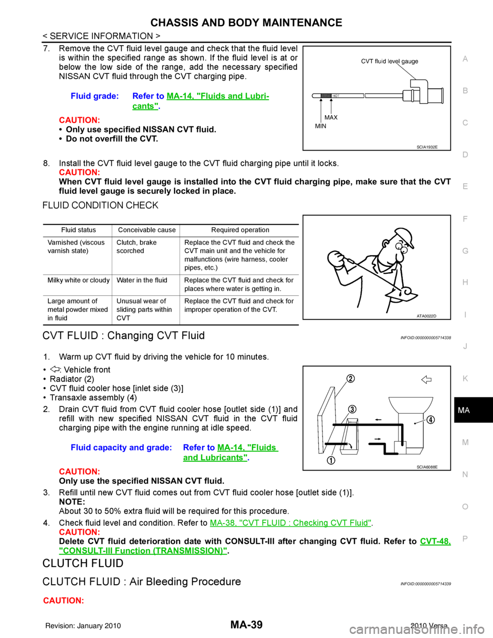
7. Remove the CVT fluid level gauge and check that the fluid level is within the specified range as shown. If the fluid level is at or
below the low side of the range, add the necessary specified
NISSAN CVT fluid through the CVT charging pipe.
CAUTION:
• Only use specified NISSAN CVT fluid.
• Do not overfill the CVT.
8. Install the CVT fluid level gauge to the CVT fluid charging pipe until it locks. CAUTION:
When CVT fluid level gauge is installed into the CVT fluid charging pipe, make sure that the CVT
fluid level gauge is securely locked in place.
FLUID CONDITION CHECK
CVT FLUID : Changing CVT FluidINFOID:0000000005714338
1. Warm up CVT fluid by driving the vehicle for 10 minutes.
• : Vehicle front
• Radiator (2)
• CVT fluid cooler hose [inlet side (3)]
• Transaxle assembly (4)
2. Drain CVT fluid from CVT fluid cooler hose [outlet side (1)] and refill with new specified NISSAN CVT fluid in the CVT fluid
charging pipe with the engine running at idle speed.
CAUTION:
Only use the specifi ed NISSAN CVT fluid.
3. Refill until new CVT fluid comes out from CVT fluid cooler hose [outlet side (1)]. NOTE:
About 30 to 50% extra fluid will be required for this procedure.
4. Check fluid level and condition. Refer to MA-38, "
CVT FLUID : Checking CVT Fluid".
CAUTION:
Delete CVT fluid deterioration date with CONSULT-III after changing CVT fluid. Refer to CVT-48,
"CONSULT-III Function (TRANSMISSION)".
CLUTCH FLUID
CLUTCH FLUID : Air Bleeding ProcedureINFOID:0000000005714339
CAUTION:Fluid grade: Refer to
MA-14, "
Fluids and Lubri-
cants".
SCIA1932E
Fluid status Conceivable cause Required operation
Varnished (viscous
varnish state) Clutch, brake
scorchedReplace the CVT fluid and check the
CVT main unit and the vehicle for
malfunctions (wire harness, cooler
pipes, etc.)
Milky white or cloudy Water in the fluid Replace the CVT fluid and check for places where water is getting in.
Large amount of
metal powder mixed
in fluid Unusual wear of
sliding parts within
CVTReplace the CVT fluid and check for
improper operation of the CVT.
ATA0022D
Fluid capacity and grade: Refer to
MA-14, "Fluids
and Lubricants".SCIA6088E
Revision: January 20102010 Versa
Page 3429 of 3745
PG-46
< SERVICE INFORMATION >
HARNESS
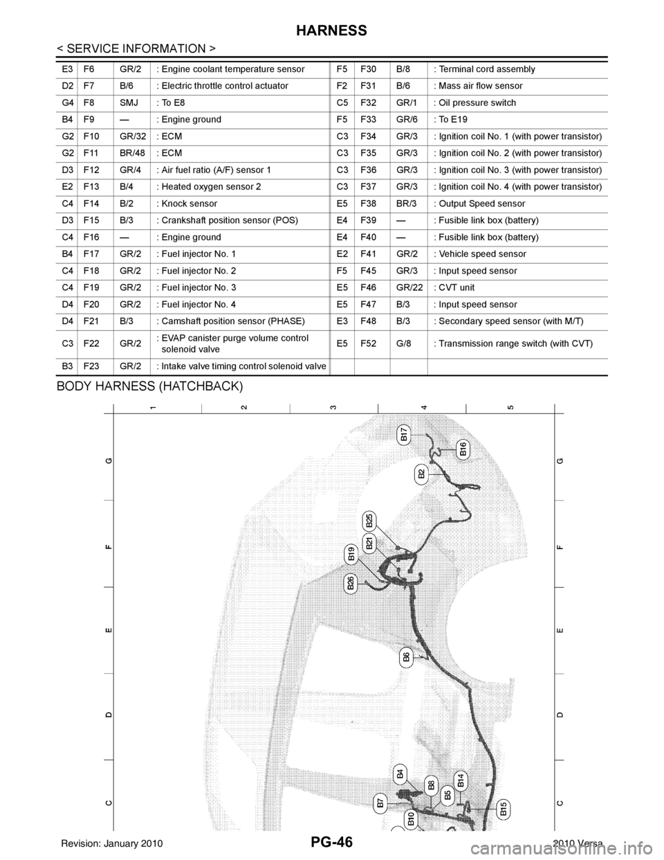
BODY HARNESS (HATCHBACK)
E3 F6 GR/2 : Engine coolant temperature sensor F5 F30 B/8 : Terminal cord assembly
D2 F7 B/6 : Electric throttle control actuatorF2 F31 B/6 : Mass air flow sensor
G4 F8 SMJ : To E8 C5 F32 GR/1 : Oil pressure switch
B4 F9 — : Engine ground F5 F33 GR/6 : To E19
G2 F10 GR/32 : ECM C3 F34 GR/3 : Ignition coil No. 1 (with power transistor)
G2 F11 BR/48 : ECM C3 F35 GR/3 : Ignition coil No. 2 (with power transistor)
D3 F12 GR/4 : Air fuel ratio (A/F) sensor 1 C3 F36 GR/3 : Ignition coil No. 3 (with power transistor)
E2 F13 B/4 : Heated oxygen sensor 2 C3 F37 GR/3 : Ignition coil No. 4 (with power transistor)
C4 F14 B/2 : Knock sensor E5 F38 BR/3 : Output Speed sensor
D3 F15 B/3 : Crankshaft position sensor (POS) E4 F39 — : Fusible link box (battery)
C4 F16 — : Engine ground E4 F40 — : Fusible link box (battery)
B4 F17 GR/2 : Fuel injector No. 1 E2 F41 GR/2 : Vehicle speed sensor
C4 F18 GR/2 : Fuel injector No. 2 F5 F45 GR/3 : Input speed sensor
C4 F19 GR/2 : Fuel injector No. 3E5 F46 GR/22 : CVT unit
D4 F20 GR/2 : Fuel injector No. 4 E5 F47 B/3 : Input speed sensor
D4 F21 B/3 : Camshaft position sensor (PHASE) E3 F48 B/3 : Secondary speed sensor (with M/T)
C3 F22 GR/2 : EVAP canister purge volume control
solenoid valve E5 F52 G/8 : Transmission range switch (with CVT)
B3 F23 GR/2 : Intake valve timing control solenoid valve
Revision: January 20102010 Versa
Page 3443 of 3745

PG-60
< SERVICE INFORMATION >
HARNESS
HEATERMTC Heater System
H/LAMP LT Headlamp
H/PHON AV Hands Free Telephone
HORN WW Horn
HO2S2 EC Heated Oxygen Sensor 2
HO2S2H EC Heated Oxygen Sensor 2 Heater
IATS EC Intake Air Temperature Sensor
IGNSYS EC Ignition System
I/KEY BL Intelligent Key System
ILL LT Illumination
INJECT EC Injector
INT/L LT Room/Map, Vanity and Luggage Lamps
IVC EC Intake Valve Timing Control Solenoid Valve
KEYLES BL Remote Keyless Entry System
KS EC Knock Sensor
LPSV AT Line Pressure Solenoid Valve
LPSV CVT Line Pressure Solenoid Valve
L/USSV CVT Lock-up Select Solenoid Valve
MAFS EC Mass Air Flow Sensor
MAIN AT Main Power Supply and Ground Circuit
MAIN EC Main Power Supply and Ground Circuit
METER DI Speedometer, Tachometer, Temp. and Fuel Gauges
MIL/DL EC Malfunction Indicator Lamp
MIRROR GW Door Mirror
NATS BL Nissan Anti-Theft System
NONDTC AT Non-detectable Item
NONDTC CVT Non-detectable Item
ODSW CVT Overdrive Control Switch
OVRCSV AT Over Run Clutch Solenoid Valve
P/SCKT WW Power Socket
PGC/V EC EVAP Canister Purge Volume Control Solenoid Valve
PHASE EC Camshaft Position Sensor (PHASE)
PNP/SW AT Park/Neutral Position Switch
PNP/SW EC Park/Neutral Position Switch
POS EC Crankshaft Position Sensor (POS)
POWER CVT Transmission Control Module (Power Supply)
PRE/SE EC EVAP Control System Pressure Sensor
PRIPS CVT Primary Pressure Sensor
PRSCVT CVT Primary Speed Sensor CVT (Input Speed Sensor)
PT/SEN AT Powertrain Revolution Sensor
RP/SEN EC Refrigerant Pressure Sensor
SECPS CVT Secondary Pressure Sensor
SECPSV CVT Secondary Speed Sensor CVT (Input Speed Sensor)
SEN/PW EC Sensor Power Supply
SESCVT CVT Secondary Pressu re Sensor Solenoid Valve
SHIFT AT A/T Shift Lock System
SHIFT CVT CVT Shift Lock System
SROOF RF Sunroof
SRS SRS Supplemental Restraint System
SSV/A AT Shift Solenoid Valve A
SSV/B AT Shift Solenoid Valve B
START SC Starting System
Revision: January 20102010 Versa
Page 3444 of 3745

HARNESSPG-61
< SERVICE INFORMATION >
C
DE
F
G H
I
J
L
M A
B
PG
N
O P
STM CVT Step Motor
STOP/L LT Stop Lamp
TCV AT Torque Converter Clutch Solenoid Valve
TCV CVT Torque Converter Clutch Solenoid Valve
T/LID BL Trunk Lid Opener
T/WARN WT Low Tire Pressure Warning System
TAIL/L LT Parking, License and Tail Lamps
TPS1 EC Throttle Position Sensor
TPS2 EC Throttle Position Sensor
TPS3 EC Throttle Position Sensor
TR/SW CVT Transmission Range Switch
TURN LT Turn Signal and Hazard Warning Lamps
VDC BRC Vehicle Dynamic Control System
VEHSEC BL Vehicle Security (Theft Warning) System
VENT/V EC EVAP Canister Vent Control Valve
VSSA/T AT Vehicle Speed Sensor A/T (Input Speed Sensor)
VSSMTR AT Vehicle Speed Sensor MTR
WARN DI Warning Lamps
WINDOW GW Power Window
WIP/R WW Rear Wiper and Washer
WIPER WW Front Wiper and Washer
Revision: January 20102010 Versa
Page 3548 of 3745

STARTING SYSTEMSC-9
< SERVICE INFORMATION >
C
DE
F
G H
I
J
L
M A
B
SC
N
O P
STARTING SYSTEM
System DescriptionINFOID:0000000005394861
M/T Models
Power is supplied at all times
• to starter motor terminal B, and
• through 40A fusible link (letter h, located in the fuse and fusible link box)
• to ignition switch terminal B.
With the ignition switch in the START position, power is supplied
• from ignition switch terminal ST
• to IPDM E/R terminal 21.
With the ignition switch in the ON or START position, power is supplied
• through 10A fuse (No. 49, located in the IPDM E/R)
• to the clutch interlock switch terminal 1.
With the clutch pedal depressed, power is supplied
• through the clutch interlock switch terminal 2
• to IPDM E/R terminal 35.
Ground is supplied at all times
• to IPDM E/R terminals 39 and 59
• through body grounds E15 and E24.
If the IPDM E/R receives a starter relay request ON signal from the BCM over the CAN communication lines,
the IPDM E/R grounds the starter relay and power is supplied
• through terminal 19 of the IPDM E/R
• to terminal S of the starter motor.
The starter motor magnetic switch energizes closing the circuit between the battery and the starter motor. The
starter motor is case ground through the cylinder block. With power and ground supplied, the starter motor
operates.
A/T Models
Power is supplied at all times
• to starter motor terminal B, and
• through 40A fusible link (letter h, located in the fuse and fusible link box)
• to ignition switch terminal B.
With the ignition switch in the START position, power is supplied
• from ignition switch terminal ST
• to IPDM E/R terminal 21.
With the ignition switch in the ON or START position, power is supplied
• through 10A fuse (No. 54, located in the IPDM E/R)
• to transmission range switch terminal 1.
With the selector lever in the P or N position, power is supplied
• through transmission range switch terminal 2
• to IPDM E/R terminal 35.
Ground is supplied at all times
• to IPDM E/R terminals 39 and 59
• through body grounds E15 and E24.
If the IPDM E/R receives a starter relay request ON signal from the BCM over the CAN communication lines,
the IPDM E/R grounds the starter relay and power is supplied
• through terminal 19 of the IPDM E/R
• to terminal S of the starter motor.
The starter motor magnetic switch energizes closing the circuit between the battery and the starter motor. The
starter motor is case ground through the cylinder block. With power and ground supplied, the starter motor
operates.
CVT Models
Power is supplied at all times
• to starter motor terminal B, and
• through 40A fusible link (letter h, located in the fuse and fusible link box)
• to ignition switch terminal B.
With the ignition switch in the START position, power is supplied
• from ignition switch terminal ST
Revision: January 20102010 Versa