2010 NISSAN TIIDA Output speed sensor
[x] Cancel search: Output speed sensorPage 19 of 3745

AT-2
Wiring Diagram - AT - TR/SW ................................91
Diagnosis Procedure ..............................................92
Component Inspection ............................................94
P0710 TRANSMISSION FLUID TEMPERA-
TURE SENSOR A ..............................................
95
Description ........................................................... ...95
CONSULT-III Reference Value in Data Monitor
Mode .................................................................... ...
95
On Board Diagnosis Logic ......................................95
Possible Cause .......................................................95
DTC Confirmation Procedure .................................95
Wiring Diagram - AT - FTS .....................................96
Diagnosis Procedure ..............................................96
Component Inspection ............................................99
P0720 OUTPUT SPEED SENSOR ..................100
Description ........................................................... ..100
CONSULT-III Reference Value in Data Monitor
Mode .................................................................... ..
100
On Board Diagnosis Logic .....................................100
Possible Cause ......................................................100
DTC Confirmation Procedure ................................100
Wiring Diagram - AT - VSSA/T ..............................101
Diagnosis Procedure ........................................... ..102
P0725 ENGINE SPEED ...................................105
Description ........................................................... ..105
CONSULT-III Reference Value in Data Monitor
Mode .................................................................... ..
105
On Board Diagnosis Logic .....................................105
Possible Cause ......................................................105
DTC Confirmation Procedure ................................105
Wiring Diagram - AT - ENGSS ..............................106
Diagnosis Procedure .............................................107
P0731 1GR INCORRECT RATIO ....................109
Description ........................................................... ..109
On Board Diagnosis Logic .....................................109
Possible Cause ......................................................109
DTC Confirmation Procedure ................................109
Diagnosis Procedure .............................................110
P0732 2GR INCORRECT RATIO ....................112
Description ........................................................... ..112
On Board Diagnosis Logic .....................................112
Possible Cause ......................................................112
DTC Confirmation Procedure ................................112
Diagnosis Procedure .............................................113
P0733 3GR INCORRECT RATIO ....................115
Description ........................................................... ..115
On Board Diagnosis Logic .....................................115
Possible Cause ......................................................115
DTC Confirmation Procedure ................................115
Diagnosis Procedure .............................................116
P0734 4GR INCORRECT RATIO ....................118
Description ........................................................... ..118
CONSULT-III Reference Value in Data Monitor
Mode .................................................................... .
118
On Board Diagnosis Logic ....................................118
Possible Cause .....................................................118
DTC Confirmation Procedure ................................118
Diagnosis Procedure .............................................119
P0740 TORQUE CONVERTER ........................123
Description ........................................................... .123
CONSULT-III Reference Value in Data Monitor
Mode .................................................................... .
123
On Board Diagnosis Logic ....................................123
Possible Cause .....................................................123
DTC Confirmation Procedure ................................123
Wiring Diagram - AT - TCV ...................................124
Diagnosis Procedure .............................................125
Component Inspection ..........................................126
P0744 TORQUE CONVERTER ........................128
Description ........................................................... .128
CONSULT-III Reference Value in Data Monitor
Mode .................................................................... .
128
On Board Diagnosis Logic ....................................128
Possible Cause .....................................................128
DTC Confirmation Procedure ................................128
Diagnosis Procedure .............................................129
P0745 PRESSURE CONTROL SOLENOID A ..133
Description ........................................................... .133
CONSULT-III Reference Value in Data Monitor
Mode .................................................................... .
133
On Board Diagnosis Logic ....................................133
Possible Cause .....................................................133
DTC Confirmation Procedure ................................133
Wiring Diagram - AT - LPSV .................................134
Diagnosis Procedure .............................................135
Component Inspection ..........................................137
P0750 SHIFT SOLENOID A .............................138
Description ............................................................138
CONSULT-III Reference Value in Data Monitor
Mode .................................................................... .
138
On Board Diagnosis Logic ....................................138
Possible Cause .....................................................138
DTC Confirmation Procedure ................................138
Wiring Diagram - AT - SSV/A ................................139
Diagnosis Procedure ............................................ .140
Component Inspection ..........................................141
P0755 SHIFT SOLENOID B .............................143
Description ............................................................143
CONSULT-III Reference Value in Data Monitor
Mode .................................................................... .
143
On Board Diagnosis Logic ....................................143
Possible Cause .....................................................143
DTC Confirmation Procedure ................................143
Wiring Diagram - AT - SSV/B ................................144
Diagnosis Procedure ............................................ .145
Component Inspection ..........................................146
Revision: January 20102010 Versa
Page 21 of 3745

AT-4
Transmission Range Switch ..................................225
Output Speed Sensor ............................................227
Input Speed Sensor ...............................................228
Differential Side Oil Seal ........................................229
AIR BREATHER HOSE ...................................232
Removal and Installation ..................................... ..232
TRANSAXLE ASSEMBLY ..............................233
Removal and Installation ..................................... ..233
OVERHAUL .................................................... .237
Component .......................................................... ..237
Oil Channel ............................................................250
Location of Adjusting Shims, Needle Bearings and
Thrust Washers .....................................................
253
Location of Snap Rings .........................................255
DISASSEMBLY .............................................. .257
Disassembly ........................................................ ..257
REPAIR FOR COMPONENT PARTS ..............275
Manual Shaft ....................................................... ..275
Oil Pump ................................................................278
Control Valve Assembly ........................................281
Control Valve Upper Body .....................................290
Control Valve Lower Body ................................... ..294
Reverse Clutch ......................................................297
High Clutch ............................................................302
Forward and Overrun Clutches .............................307
Low & Reverse Brake ............................................314
Rear Internal Gear and Forward Clutch Hub .........318
Output Shaft, Output Gear, Idler Gear, Reduction
Pinion Gear and Bearing Retainer .........................
322
Band Servo Piston Assembly ................................331
Final Drive .............................................................337
ASSEMBLY .....................................................344
Assembly (1) ........................................................ ..344
Adjustment (1) (For HR16DE Engine Models) ..... .345
Adjustment (1) (For MR18DE Engine Models) .....349
Assembly (2) .........................................................355
Adjustment (2) .......................................................360
Assembly (3) .........................................................363
SERVICE DATA AND SPECIFICATIONS
(SDS) ................................................................
373
General Specification ........................................... .373
Vehicle Speed at Which Gear Shifting Occurs .....373
Vehicle Speed at When Lock-up Occurs/Releases
.
373
Stall Speed ............................................................374
Line Pressure ........................................................374
Adjusting shims, Needle Bearings, Thrust Wash-
ers and Snap Rings ..............................................
374
Control Valves .......................................................375
Accumulator ..........................................................376
Clutches and Brakes .............................................376
Final Drive .............................................................378
Planetary Carrier ...................................................378
Oil Pump ...............................................................378
Input Shaft .............................................................378
Reduction Pinion Gear ..........................................378
Band Servo ...........................................................378
Output Shaft ..........................................................379
Bearing Retainer ...................................................379
Total End Play ...................................................... .379
Reverse Clutch End Play ......................................379
Removal and Installation .......................................379
Shift Solenoid Valves ........................................... .379
Solenoid Valves ....................................................380
A/T Fluid Temperature Sensor ..............................380
Output Speed Sensor ...........................................380
Dropping Resistor .................................................380
Input Speed Sensor ..............................................380
Revision: January 20102010 Versa
Page 22 of 3745

INDEX FOR DTCAT-5
< SERVICE INFORMATION >
DE
F
G H
I
J
K L
M A
B
AT
N
O P
SERVICE INFORMATION
INDEX FOR DTC
Alphabetical IndexINFOID:0000000005397207
NOTE:
If DTC “CAN COMM CIRCUIT” is di splayed with other DTCs, first perform the trouble diagnosis for
DTC “CAN COMM CIRCUIT”. Refer to AT- 8 7
.
*1: These numbers is prescribed by SAE J2012.
*2: When the fail-safe operation occurs, the MIL illuminates.
*3: The MIL illuminates when both the “Output speed sensor signal” and the “Vehicle speed signal” meet the fail-safe condition at the
same time.
DTC No. IndexINFOID:0000000005397208
NOTE:
If DTC “CAN COMM CIRCUIT” is di splayed with other DTCs, first perform the trouble diagnosis for
DTC “CAN COMM CIRCUIT”. Refer to AT- 8 7
.
Items
(CONSULT-III screen terms) DTC*1Reference page
CONSULT-III or GST
BATT/FLUID TEMP SEN —AT-156
CAN COMM CIRCUIT U1000AT- 8 7
CONTROL UNIT (RAM) —AT-167
CONTROL UNIT (ROM) —AT-167
ENGINE SPEED P0725AT-105
FLUID TEMP SENSOR A P0710AT- 9 5
INPUT SPEED SENSOR A —AT-162
OUTPUT SPEED SENSOR*3P0720 AT-100
OVER CLUTCH SOLENOID P1760AT-148
PC SOLENOID A P0745AT-133
SHIFT SOLENOID A*2P0750 AT-138
SHIFT SOLENOID B*2P0755AT-143
TORQUE CONVERTER P0740AT-123
TORQUE CONVERTER P0744AT-128
T/M RANGE SENSOR A P0705AT- 9 0
VHCL SPEED SEN-MTR —AT-153
1GR INCORRECT RATIO P0731AT-109
2GR INCORRECT RATIO P0732AT- 11 2
3GR INCORRECT RATIO P0733AT- 11 5
4GR INCORRECT RATIO P0734AT- 11 8
DTC*1Items
(CONSULT-III screen terms) Reference page
CONSULT-III or GST
P0705 T/M RANGE SENSOR A AT- 9 0
P0710FLUID TEMP SENSOR A AT- 9 5
P0720
OUTPUT SPEED SENSOR*3AT- 1 0 0
P0725ENGINE SPEED AT- 1 0 5
P07311GR INCORRECT RATIO AT- 1 0 9
Revision: January 20102010 Versa
Page 47 of 3745
AT-30
< SERVICE INFORMATION >
A/T CONTROL SYSTEM
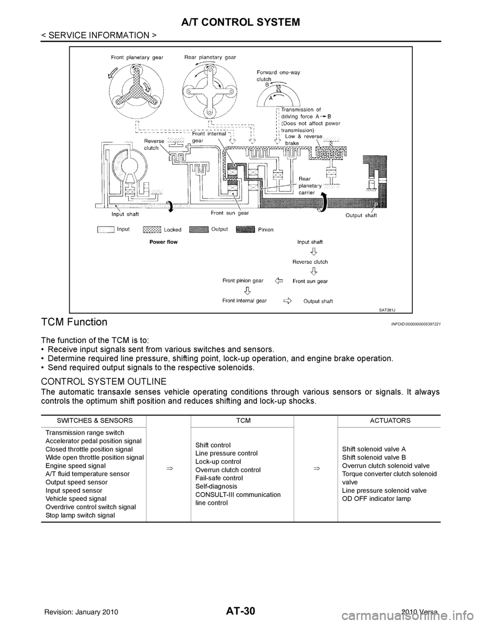
TCM Function
INFOID:0000000005397221
The function of the TCM is to:
• Receive input signals sent from various switches and sensors.
• Determine required line pressure, shifting poi nt, lock-up operation, and engine brake operation.
• Send required output signals to the respective solenoids.
CONTROL SYSTEM OUTLINE
The automatic transaxle senses vehicle operating conditions through various sensors or signals. It always
controls the optimum shift position and reduces shifting and lock-up shocks.
SAT381J
SWITCHES & SENSORS
⇒TCM
⇒ACTUATORS
Transmission range switch
Accelerator pedal position signal
Closed throttle position signal
Wide open throttle position signal
Engine speed signal
A/T fluid temperature sensor
Output speed sensor
Input speed sensor
Vehicle speed signal
Overdrive control switch signal
Stop lamp switch signal Shift control
Line pressure control
Lock-up control
Overrun clutch control
Fail-safe control
Self-diagnosis
CONSULT-III communication
line control
Shift solenoid valve A
Shift solenoid valve B
Overrun clutch solenoid valve
Torque converter clutch solenoid
valve
Line pressure solenoid valve
OD OFF indicator lamp
Revision: January 20102010 Versa
Page 48 of 3745
A/T CONTROL SYSTEMAT-31
< SERVICE INFORMATION >
DE
F
G H
I
J
K L
M A
B
AT
N
O P
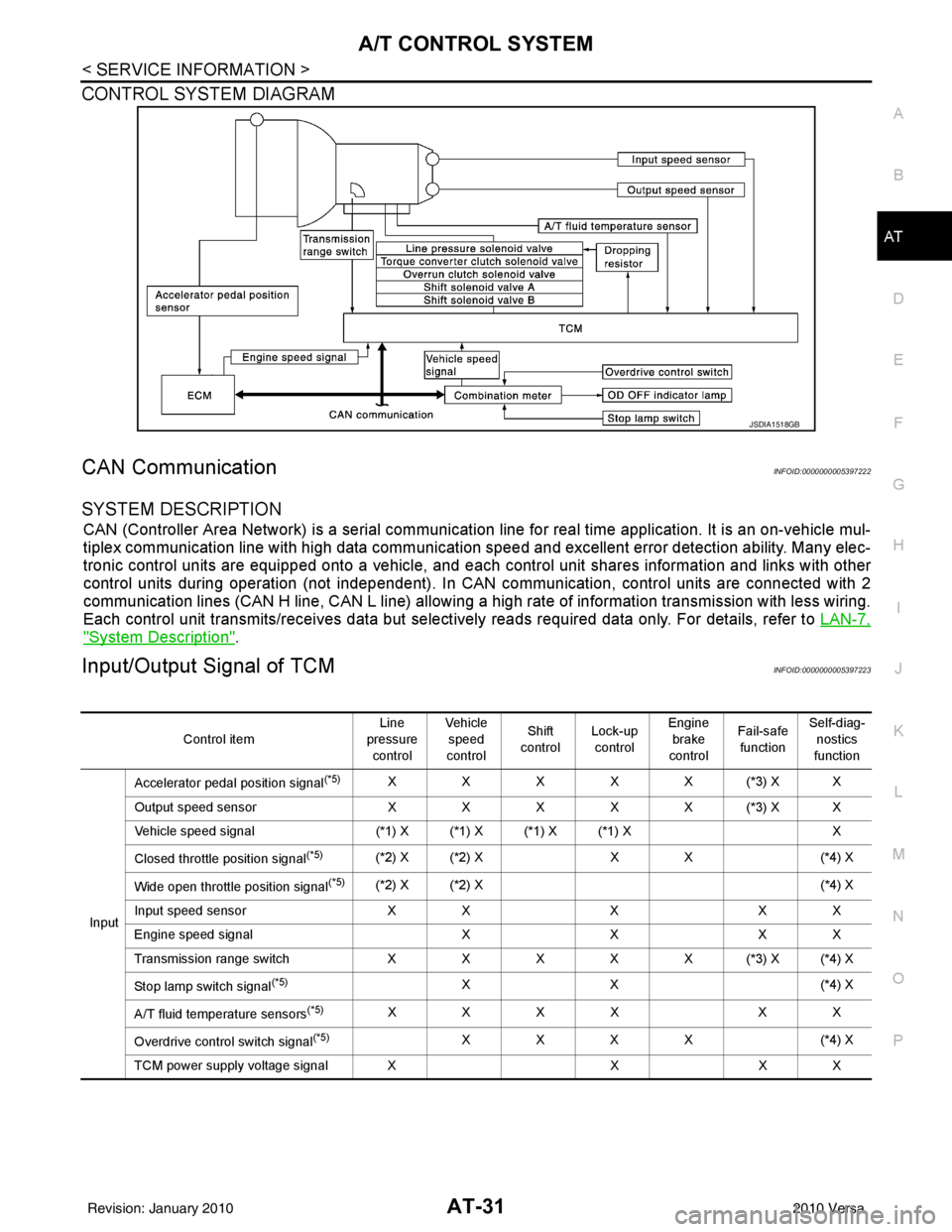
CONTROL SYSTEM DIAGRAM
CAN CommunicationINFOID:0000000005397222
SYSTEM DESCRIPTION
CAN (Controller Area Network) is a serial communication line for real time application. It is an on-vehicle mul-
tiplex communication line with high data communication speed and excellent error detection ability. Many elec-
tronic control units are equipped onto a vehicle, and each control unit shares information and links with other
control units during operation (not independent). In CAN communication, control units are connected with 2
communication lines (CAN H line, CAN L line) allowing a high rate of information transmission with less wiring.
Each control unit transmits/receives data but selectively reads required data only. For details, refer to LAN-7,
"System Description".
Input/Output Signal of TCMINFOID:0000000005397223
JSDIA1518GB
Control itemLine
pressure control Veh icl e
speed
control Shift
control Lock-up
control Engine
brake
control Fail-safe
function Self-diag-
nostics
function
Input Accelerator pedal position signal
(*5)XXXXX(*3) XX
Output speed sensor X X X X X (*3) X X
Vehicle speed signal (*1) X (*1) X (*1) X (*1) X X
Closed throttle position signal
(*5)(*2) X (*2) X X X(*4) X
Wide open throttle position signal
(*5)(*2) X (*2) X (*4) X
Input speed sensor X XXX X
Engine speed signal XXX X
Transmission range sw itch XXXXX(*3) X(*4) X
Stop lamp switch signal
(*5)XX ( *4 ) X
A/T fluid temperature sensors
(*5)XXXX XX
Overdrive control switch signal
(*5)XXXX (*4) X
TCM power supply voltage signal X XX X
Revision: January 20102010 Versa
Page 49 of 3745
AT-32
< SERVICE INFORMATION >
A/T CONTROL SYSTEM
*1: Output speed sensor
*2: Spare for accelerator pedal position signal
*3: If these input and output signals are different, the TCM triggers the fail-safe function.
*4: Used as a condition for starting self-diagnostics; if self-diagnosis are not started, it is judged that there is some kind of error.
*5: Input by CAN communications.
*6: Output by CAN communications.
Line Pressure ControlINFOID:0000000005397224
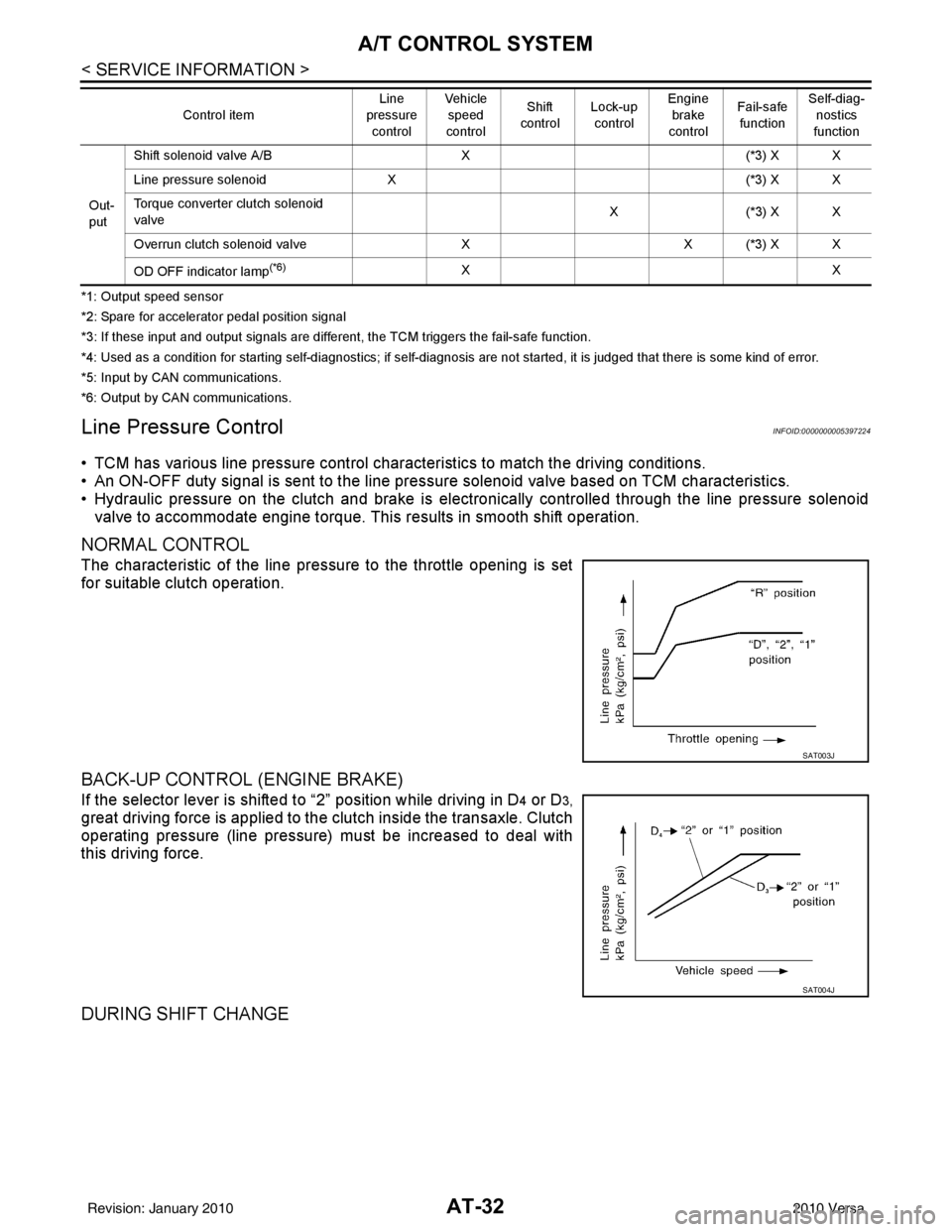
• TCM has various line pressure control char acteristics to match the driving conditions.
• An ON-OFF duty signal is sent to the line pres sure solenoid valve based on TCM characteristics.
• Hydraulic pressure on the clutch and brake is electronically controlled through the line pressure solenoid valve to accommodate engine torque. This results in smooth shift operation.
NORMAL CONTROL
The characteristic of the line pressure to the throttle opening is set
for suitable clutch operation.
BACK-UP CONTROL (ENGINE BRAKE)
If the selector lever is shifted to “2” position while driving in D4 or D3,
great driving force is applied to the clutch inside the transaxle. Clutch
operating pressure (line pressure) must be increased to deal with
this driving force.
DURING SHIFT CHANGE
Out-
put Shift solenoid valve A/B
X(*3) X X
Line pressure solenoid X (*3) X X
Torque converter clutch solenoid
valve X(
*3 ) X X
Overrun clutch solenoid valve XX (*3) X X
OD OFF indicator lamp
(*6)XX
Control item
Line
pressure
control Vehicle
speed
control Shift
control Lock-up
control Engine
brake
control Fail-safe
function Self-diag-
nostics
function
SAT003J
SAT004J
Revision: January 20102010 Versa
Page 50 of 3745
A/T CONTROL SYSTEMAT-33
< SERVICE INFORMATION >
DE
F
G H
I
J
K L
M A
B
AT
N
O P
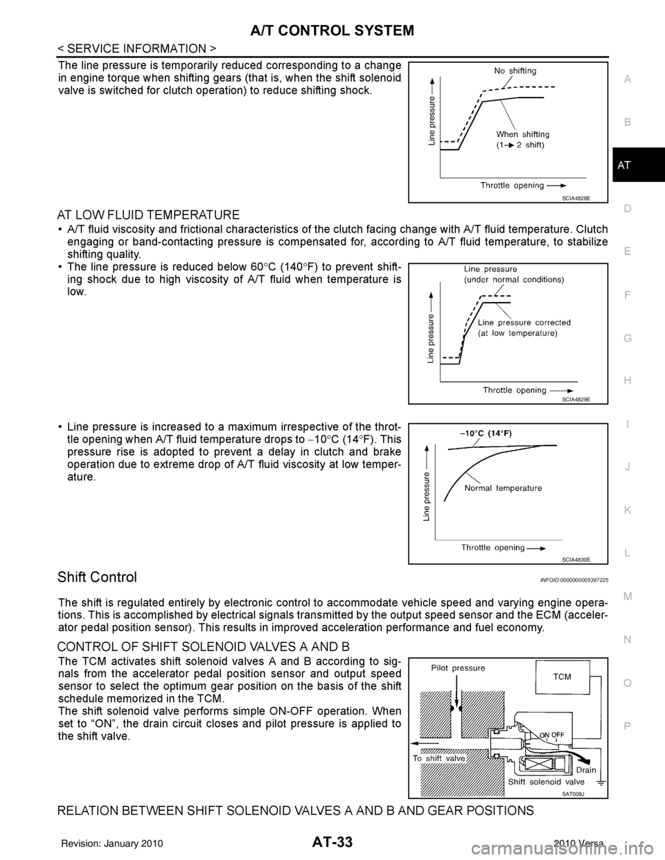
The line pressure is temporarily reduced corresponding to a change
in engine torque when shifting gears (that is, when the shift solenoid
valve is switched for clutch operation) to reduce shifting shock.
AT LOW FLUID TEMPERATURE
• A/T fluid viscosity and frictional characteristics of t he clutch facing change with A/T fluid temperature. Clutch
engaging or band-contacting pressure is compensated for, according to A/T fluid temperature, to stabilize
shifting quality.
• The line pressure is reduced below 60 °C (140° F) to prevent shift-
ing shock due to high viscosity of A/T fluid when temperature is
low.
• Line pressure is increased to a maximum irrespective of the throt- tle opening when A/T fluid temperature drops to −10° C (14° F). This
pressure rise is adopted to prevent a delay in clutch and brake
operation due to extreme drop of A/T fluid viscosity at low temper-
ature.
Shift ControlINFOID:0000000005397225
The shift is regulated entirely by electronic cont rol to accommodate vehicle speed and varying engine opera-
tions. This is accomplished by electrical signals trans mitted by the output speed sensor and the ECM (acceler-
ator pedal position sensor). This results in improved acceleration performance and fuel economy.
CONTROL OF SHIFT SOLENOID VALVES A AND B
The TCM activates shift solenoid valves A and B according to sig-
nals from the accelerator pedal position sensor and output speed
sensor to select the optimum gear position on the basis of the shift
schedule memorized in the TCM.
The shift solenoid valve performs simple ON-OFF operation. When
set to “ON”, the drain circuit closes and pilot pressure is applied to
the shift valve.
RELATION BETWEEN SHIFT SOLENOID VALVES A AND B AND GEAR POSITIONS
SCIA4828E
SCIA4829E
SCIA4830E
SAT008J
Revision: January 20102010 Versa
Page 56 of 3745
ON BOARD DIAGNOSTIC (OBD) SYSTEMAT-39
< SERVICE INFORMATION >
DE
F
G H
I
J
K L
M A
B
AT
N
O P
ON BOARD DIAGNOSTIC (OBD) SYSTEM
IntroductionINFOID:0000000005397230
A/T system has two self-diagnostic systems.
The first is emission-related on board diagnostic system (OBD-II) performed by the TCM in combination with
the ECM. The malfunction is indicated by the MIL (malf unction indicator lamp) and is stored as a DTC in the
ECM memory but not the TCM memory.
The second is the TCM original self-diagnosis indicated by the OD OFF indicator lamp. The malfunction is
stored in the TCM memory. The detected items are ov erlapped with OBD-II self-diagnostic items. For detail,
refer to AT-77, "
CONSULT-III Function (TRANSMISSION)" .
OBD-II Function for A/T SystemINFOID:0000000005397231
The ECM provides emission-related on board diagnostic (O BD-II) functions for the A/T system. One function
is to receive a signal from the TCM used with OBD-rela ted parts of the A/T system. The signal is sent to the
ECM when a malfunction occurs in the corresponding OBD-re lated part. The other function is to indicate a
diagnostic result by means of the MIL (malfunction indica tor lamp) on the instrument panel. Sensors, switches
and solenoid valves are used as sensing elements.
The MIL automatically illuminates in One or Two Trip Detection Logic when a malfunction is sensed in relation
to A/T system parts.
One or Two Trip Detection Logic of OBD-IIINFOID:0000000005397232
ONE TRIP DETECTION LOGIC
If a malfunction is sensed during the first test drive, the MIL will illuminate and the malfunction will be stored in
the ECM memory as a DTC. The TCM is not provided with such a memory function.
TWO TRIP DETECTION LOGIC
When a malfunction is sensed during the first test drive, it is stored in the ECM memory as a 1st trip DTC
(diagnostic trouble code) or 1st trip freeze frame data. At this point, the MIL will not illuminate. — 1st trip
If the same malfunction as that experienced during the fi rst test drive is sensed during the second test drive,
the MIL will illuminate. — 2nd trip
The “trip” in the “One or Two Trip Detection Logic” m eans a driving mode in which self-diagnosis is performed
during vehicle operation.
OBD-II Diagnostic Trouble Code (DTC)INFOID:0000000005397233
HOW TO READ DTC AND 1ST TRIP DTC
DTC and 1st trip DTC can be read by the following methods.
( with CONSULT-III or GST) CONSULT-III or GST (Generic Scan Tool) Examples: P0705, P0720 etc.
These DTC are prescribed by SAE J2012.
(CONSULT-III also displays the malfunctioning component or system.)
• 1st trip DTC No. is the same as DTC No.
• Output of the diagnostic trouble code indicates that the indicated circuit has a malfunction. How-
ever, in case of the Mode II and GST, they do not indicate whether the malfunction is still occurring or
occurred in the past and returned to normal.
CONSULT-III can identify them as shown below, therefore, CONS ULT-III (if available) is recom-
mended.
DTC or 1st trip DTC of a malfunction is displayed in SELF-DIAGNOSTIC RESULTS mode for “ENGINE” with
CONSULT-III. Time data indicates how many times the vehicle was driven after the last detection of a DTC.
If the DTC is being detected curr ently, the time data will be “0”.
If a 1st trip DTC is stored in the ECM, the time data will be “1t”.
Freeze Frame Data and 1st Trip Freeze Frame Data
The ECM has a memory function, which stores the driv ing condition such as fuel system status, calculated
load value, engine coolant temperature, short term f uel trim, long term fuel trim, engine speed and vehicle
speed at the moment the ECM detects a malfunction.
Revision: January 20102010 Versa