2010 NISSAN TIIDA low beam
[x] Cancel search: low beamPage 1223 of 3745

COMBINATION METERSDI-13
< SERVICE INFORMATION >
C
DE
F
G H
I
J
L
M A
B
DI
N
O P
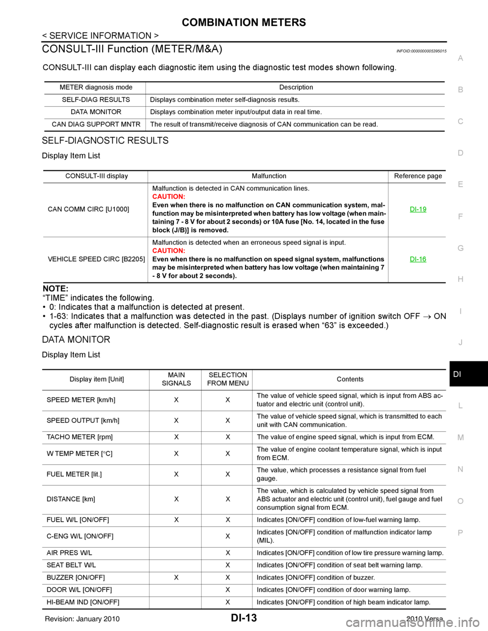
CONSULT-III Function (METER/M&A)INFOID:0000000005395015
CONSULT-III can display each diagnostic item us ing the diagnostic test modes shown following.
SELF-DIAGNOSTIC RESULTS
Display Item List
NOTE:
“TIME” indicates the following.
• 0: Indicates that a malfunction is detected at present.
• 1-63: Indicates that a malfunction was detected in the past. (Displays number of ignition switch OFF → ON
cycles after malfunction is detected. Self-di agnostic result is erased when “63” is exceeded.)
DATA MONITOR
Display Item List
METER diagnosis mode Description
SELF-DIAG RESULTS Displays combination meter self-diagnosis results. DATA MONITOR Displays combination meter input/output data in real time.
CAN DIAG SUPPORT MNTR The result of transmit/receive diagnosis of CAN communication can be read.
CONSULT-III display MalfunctionReference page
CAN COMM CIRC [U1000] Malfunction is detected in CAN communication lines.
CAUTION:
Even when there is no malfuncti
on on CAN communication system, mal-
function may be misinterpreted when battery has low voltage (when main-
taining 7 - 8 V for about 2 seconds) or 10A fuse [No. 14, located in the fuse
block (J/B)] is removed. DI-19
VEHICLE SPEED CIRC [B2205]
Malfunction is detected when an erroneous speed signal is input.
CAUTION:
Even when there is no malfunction
on speed signal system, malfunctions
may be misinterpreted when battery has low voltage (when maintaining 7
- 8 V for about 2 seconds). DI-16
Display item [Unit]
MAIN
SIGNALS SELECTION
FROM MENU Contents
SPEED METER [km/h] XXThe value of vehicle speed signa
l, which is input from ABS ac-
tuator and electric unit (control unit).
SPEED OUTPUT [km/h] XXThe value of vehicle speed signal, which is transmitted to each
unit with CAN communication.
TACHO METER [rpm] XX The value of engine speed signal, which is input from ECM.
W TEMP METER [ °C] X XThe value of engine coolant temperature signal, which is input
from ECM.
FUEL METER [lit.] XXThe value, which processes a resistance signal from fuel
gauge.
DISTANCE [km] XXThe value, which is calculated by vehicle speed signal from
ABS actuator and electric unit (control unit), fuel gauge and fuel
consumption signal from ECM.
FUEL W/L [ON/OFF] XX Indicates [ON/OFF] condition of low-fuel warning lamp.
C-ENG W/L [ON/OFF] XIndicates [ON/OFF] condition of malfunction indicator lamp
(MIL).
AIR PRES W/L X Indicates [ON/OFF] condition of low tire pressure warning lamp.
SEAT BELT W/L X Indicates [ON/OFF] condition of seat belt warning lamp.
BUZZER [ON/OFF] XX Indicates [ON/OFF] condition of buzzer.
DOOR W/L [ON/OFF] X Indicates [ON/OFF] condition of door warning lamp.
HI-BEAM IND [ON/OFF] X Indicates [ON/OFF] condition of high beam indicator lamp.
Revision: January 20102010 Versa
Page 2836 of 3745
![NISSAN TIIDA 2010 Service Repair Manual CAN COMMUNICATION SYSTEMLAN-27
< SERVICE INFORMATION > [CAN]
C
D
E
F
G H
I
J
L
M A
B
LAN
N
O P
CAN Communication Signal ChartINFOID:0000000005395135
Refer to LAN-16, "How to Use CAN Communication Sig NISSAN TIIDA 2010 Service Repair Manual CAN COMMUNICATION SYSTEMLAN-27
< SERVICE INFORMATION > [CAN]
C
D
E
F
G H
I
J
L
M A
B
LAN
N
O P
CAN Communication Signal ChartINFOID:0000000005395135
Refer to LAN-16, "How to Use CAN Communication Sig](/manual-img/5/57397/w960_57397-2835.png)
CAN COMMUNICATION SYSTEMLAN-27
< SERVICE INFORMATION > [CAN]
C
D
E
F
G H
I
J
L
M A
B
LAN
N
O P
CAN Communication Signal ChartINFOID:0000000005395135
Refer to LAN-16, "How to Use CAN Communication Signal Chart" for how to use CAN communication signal
chart.
NOTE:
Refer to LAN-22, "
Abbreviation List" for the abbreviations of the connecting units.
T: Transmit R: Receive
Signal name/Connecting unitECM
BCM
EPS
I-KEY M&A
STRG ABS
TCM
*1
TCM
*2
IPDM-E
A/C compressor request signal T R
Accelerator pedal position signal T
R
*3RR
ASCD CRUISE lamp signal T R
ASCD SET lamp signal T R
Closed throttle position signal T R R
Cooling fan motor operation signal T R
Engine coolant temperature signal TR
Engine speed signal TR
R
*3R
Engine status signal T R R R
Fuel consumption monitor signal T R
Malfunction indicator lamp signal TR
Wide open throttle position signal T R R
A/C switch signal R T
Blower fan motor switch signal R T
Buzzer output signal TR
TR
Day time running light request signal
*4TR
Door lock/unlock status signal TR
Door switch signal TR R R
Front wiper request signal T R
High beam request signal TR R
Horn chirp signal T R
Ignition switch signal T R
Low beam request signal T R
Position lights request signal TR R
Rear window defogger switch signal T R
Sleep/wake up signal TRR
R
RT
Theft warning horn request signal T R
Tire pressure signal
*5TR
Trunk open/close status signal TR
Turn indicator signal TR
EPS operation signal TR
EPS warning lamp signal TR
Door lock/unlock/trunk open request signal RT
Hazard request signal RT
Ignition knob switch signal RT
Revision: January 20102010 Versa
Page 2837 of 3745
![NISSAN TIIDA 2010 Service Repair Manual LAN-28
< SERVICE INFORMATION >[CAN]
CAN COMMUNICATION SYSTEM
*1: A/T models
*2: CVT models
*3: Models with VDC
*4: Models for Canada
*5: Models for USA
*6: Models without ABS
NOTE:
CAN data of the air NISSAN TIIDA 2010 Service Repair Manual LAN-28
< SERVICE INFORMATION >[CAN]
CAN COMMUNICATION SYSTEM
*1: A/T models
*2: CVT models
*3: Models with VDC
*4: Models for Canada
*5: Models for USA
*6: Models without ABS
NOTE:
CAN data of the air](/manual-img/5/57397/w960_57397-2836.png)
LAN-28
< SERVICE INFORMATION >[CAN]
CAN COMMUNICATION SYSTEM
*1: A/T models
*2: CVT models
*3: Models with VDC
*4: Models for Canada
*5: Models for USA
*6: Models without ABS
NOTE:
CAN data of the air bag diagnosis sensor unit is not used by usual service work, thus it is omitted.
KEY warning lamp signal
T R
LOCK warning lamp signal T R
Panic alarm request signal RT
Fuel level sensor signal RT
Overdrive control switch signal TR R
Parking brake switch signal
*3TR
Stop lamp switch signal T R R
Vehicle speed signal RRRR T
RRR T R
R
*6T*6
Steering angle sensor signal*3TR
ABS warning lamp signal RT
Brake warning lamp signal RT
SLIP indicator lamp signal
*3RT
VDC OFF indicator lamp signal
*3RT
VDC warning lamp signal
*3RT
A/T check indicator signal RT
A/T self-diagnosis signal R T
Input speed signal R T
OD OFF indicator signal RT
Output shaft revolution signal R T T
Shift position indicator signal R
R
*3TT
CVT self-diagnosis signal R T
Input shaft revolution signal R T
OD OFF indicator signal RT
Front wiper stop position signal R T
High beam status signal R T
Low beam status signal R T
Oil pressure switch signal R RR T
Rear window defogger control signal R T
Signal name/Connecting unit
ECM
BCM
EPS
I-KEY M&A
STRG ABS
TCM
*1
TCM
*2
IPDM-E
Revision: January 20102010 Versa
Page 2996 of 3745

LT-1
ELECTRICAL
C
DE
F
G H
I
J
L
M
SECTION LT
A
B
LT
N
O P
CONTENTS
LIGHTING SYSTEM
SERVICE INFORMATION .. ..........................3
PRECAUTIONS .............................................. .....3
Precaution for Supplemental Restraint System
(SRS) "AIR BAG" and "SEAT BELT PRE-TEN-
SIONER" ............................................................. ......
3
Precaution Necessary for Steering Wheel Rota-
tion After Battery Disconnect ............................... ......
3
PREPARATION ...................................................5
Special Service Tool ........................................... ......5
HEADLAMP (FOR USA) .....................................6
Component Parts and Harness Connector Loca-
tion ...................................................................... ......
6
System Description ...................................................6
CAN COMMUNICATION SYSTEM DESCRIP-
TION .................................................................... ......
7
Schematic .................................................................8
Wiring Diagram .........................................................9
Terminal and Reference Value for BCM .................12
Terminal and Reference Value for IPDM E/R .........12
How to Perform Trouble Diagnosis .........................13
Preliminary Check ...................................................13
CONSULT-III Function (BCM) .................................13
CONSULT-III Function (IPDM E/R) .........................14
Headlamp High Beam Does Not Illuminate (Both
Sides) .................................................................. ....
16
Headlamp High Beam Does Not Illuminate (One
Side) .................................................................... ....
18
High Beam Indicator Lamp Does Not Illuminate .....19
Headlamp Low Beam Does Not Illuminate (Both
Sides) .................................................................. ....
20
Headlamp Low Beam Does Not Illuminate (One
Side) .................................................................... ....
22
Headlamps Do Not Turn OFF .................................23
Aiming Adjustment ..................................................24
Bulb Replacement ...................................................25
Removal and Installation .........................................26
Disassembly and Assembly ................................ ....26
HEADLAMP (FOR CANADA) - DAYTIME
LIGHT SYSTEM - ..............................................
28
Component Parts and Harness Connector Loca-
tion ....................................................................... ....
28
System Description ..................................................28
CAN Communication System Description ...............30
Schematic ................................................................31
Wiring Diagram - DTRL - .........................................32
Terminal and Reference Value for BCM ..................35
Terminal and Reference Value for IPDM E/R ...... ....35
How to Perform Trouble Diagnosis ..........................36
Preliminary Check ...................................................36
CONSULT-III Function (BCM) .................................36
CONSULT-III Function (IPDM E/R) ..................... ....36
Daytime Light Control Does Not Operate Properly
(High Beam Headlamps Operate Properly) .............
36
Aiming Adjustment ...................................................38
Bulb Replacement ...................................................39
Removal and Installation .........................................40
Disassembly and Assembly .....................................40
FRONT FOG LAMP ..........................................42
Component Parts and Harness Connector Loca-
tion ...........................................................................
42
System Description ..................................................42
CAN Communication System Description ...............43
Wiring Diagram - F/FOG - .......................................44
Terminal and Reference Value for BCM ..................45
Terminal and Reference Value for IPDM E/R ...... ....45
How to Proceed with Trouble Diagnosis ..................46
Preliminary Check ............................................... ....46
CONSULT-III Function (BCM) .................................46
CONSULT-III Function (IPDM E/R) ..................... ....46
Front Fog lamps Do Not Illuminate (Both Sides) .....46
Front Fog Lamp Does Not Illuminate (One Side) ....48
Aiming Adjustment ...................................................49
Bulb Replacement ...................................................50
Removal and Installation .........................................50
TURN SIGNAL AND HAZARD WARNING
LAMPS ..............................................................
51
Revision: January 20102010 Versa
Page 3002 of 3745

HEADLAMP (FOR USA)LT-7
< SERVICE INFORMATION >
C
DE
F
G H
I
J
L
M A
B
LT
N
O P
• to BCM terminal 67
• to combination meter terminals 21, 22 and 23
• through grounds M57 and M61, and
• to IPDM E/R terminals 39 and 59
• through grounds E15 and E24.
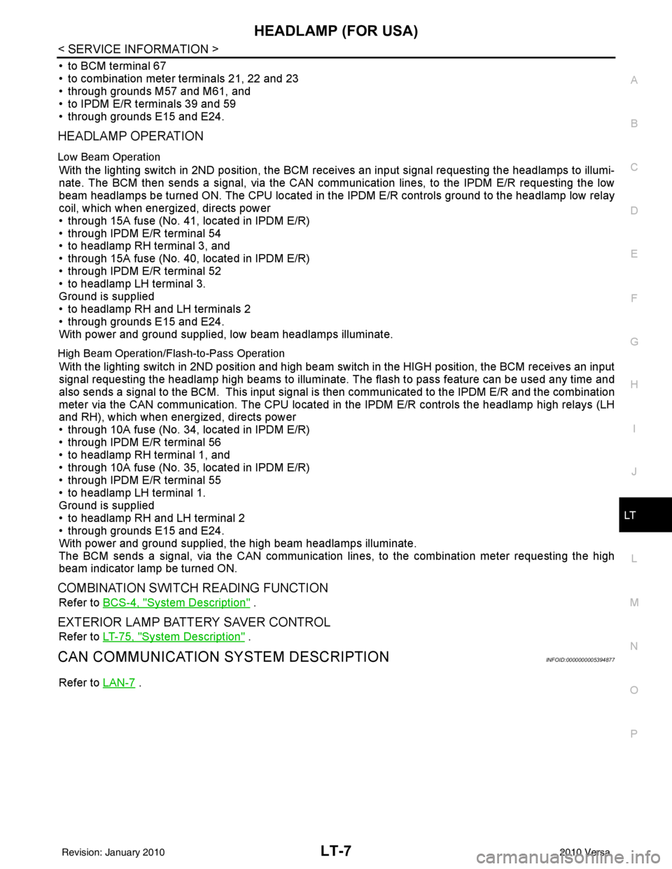
HEADLAMP OPERATION
Low Beam Operation
With the lighting switch in 2ND position, the BCM re ceives an input signal requesting the headlamps to illumi-
nate. The BCM then sends a signal, via the CAN comm unication lines, to the IPDM E/R requesting the low
beam headlamps be turned ON. The CPU located in the IPDM E/R controls ground to the headlamp low relay
coil, which when energized, directs power
• through 15A fuse (No. 41, located in IPDM E/R)
• through IPDM E/R terminal 54
• to headlamp RH terminal 3, and
• through 15A fuse (No. 40, located in IPDM E/R)
• through IPDM E/R terminal 52
• to headlamp LH terminal 3.
Ground is supplied
• to headlamp RH and LH terminals 2
• through grounds E15 and E24.
With power and ground supplied, low beam headlamps illuminate.
High Beam Operation/Flash-to-Pass Operation
With the lighting switch in 2ND position and high beam switch in the HIGH position, the BCM receives an input
signal requesting the headlamp high beams to illuminate. The flash to pass feature can be used any time and
also sends a signal to the BCM. This input signal is then communicated to the IPDM E/R and the combination
meter via the CAN communication. The CPU located in the IPDM E/R controls the headlamp high relays (LH
and RH), which when energized, directs power
• through 10A fuse (No. 34, located in IPDM E/R)
• through IPDM E/R terminal 56
• to headlamp RH terminal 1, and
• through 10A fuse (No. 35, located in IPDM E/R)
• through IPDM E/R terminal 55
• to headlamp LH terminal 1.
Ground is supplied
• to headlamp RH and LH terminal 2
• through grounds E15 and E24.
With power and ground supplied, the high beam headlamps illuminate.
The BCM sends a signal, via the CAN communication lines, to the combination meter requesting the high
beam indicator lamp be turned ON.
COMBINATION SWITCH READING FUNCTION
Refer to BCS-4, "System Description" .
EXTERIOR LAMP BATTERY SAVER CONTROL
Refer to LT-75, "System Description" .
CAN COMMUNICATION SYSTEM DESCRIPTIONINFOID:0000000005394877
Refer to LAN-7 .
Revision: January 20102010 Versa
Page 3010 of 3745

HEADLAMP (FOR USA)LT-15
< SERVICE INFORMATION >
C
DE
F
G H
I
J
L
M A
B
LT
N
O P
x: Applicable
NOTE:
The details for display of the period are as follows:
• CRNT: Error currently detected with IPDM E/R.
• PAST: Error detected in the past and placed in IPDM E/R memory.
DATA MONITOR
All Signals, Main Signals, Selection From Menu
Display items CONSULT-
III display code Malfunction detection TIME
Possible causes
CRNT PAST
NO DTC IS DETECTED.
FURTHER TESTING
MAY BE REQUIRED. ———
——
CAN COMM CIRC U1000 • If CAN communication reception/transmission
data has a malfunction, or if any of the control
units fail, data reception/transmission cannot be
confirmed.
• When the data in CAN communication is not re-
ceived before the specified time. XX
Any of items listed
below have
errors:
• TRANSMIT DIAG
•ECM
• BCM/SEC
IGN RELAY ON —When the ignition switch is not in the ON position,
the ignition relay in the IPDM E/R is ON. XX
Ignition relay (inte-
grated in IPDM E/R)
IGN RELAY OFF —When the ignition switch is not in the ON position,
the ignition relay in the IPDM E/R is OFF. XXIgnition relay (inte-
grated in IPDM E/R)
EEPROM —Malfunction is detected with the integrated EEPROM
memory diagnosis.
X X IPDM E/R
Item nameCONSULT-III
screen display Display or unit Monitor item selection
Description
ALL
SIGNALS MAIN
SIGNALS SELECTION
FROM MENU
Motor fan request MOTOR FAN
REQ1/2/3/4
X X X Signal status input from ECM
Compressor re-
quest AC COMP REQ ON/OFF
X XX Signal status input from ECM
Parking, license,
and tail lamp re-
quest TAIL & CLR REQ ON/OFF
X XX Signal status input from BCM
Headlamp low
beam request HL LO REQ ON/OFF
X XX Signal status input from BCM
Headlamp high
beam request HL HI REQ ON/OFF
X XX Signal status input from BCM
Front fog request FR FOG REQ ON/OFF X XX Signal status input from BCM
FR wiper request FR WIP REQ STOP/1LO/LO/HI X X X Signal status input from BCM
Wiper auto stop WIP AUTO
STOPACT P/STOP P X X
X Output status of IPDM E/R
Wiper protection WIP PROT OFF/LS/HS/Block X X X Control status of IPDM E/R
Starter request ST RLY REQ ON/OFF XX Status of input signal (*1)
Ignition relay
status IGN RLY ON/OFF
X XXIgnition relay status monitored
with IPDM E/R
Rear defogger re-
quest RR DEF REQ ON/OFF
X XX Signal status input from BCM
Oil pressure
switch OIL P SW OPEN/CLOSE X
XSignal status input from IPDM
E/R
Hood switch HOOD SW (*2) OFF XXSignal status input from IPDM
E/R
Revision: January 20102010 Versa
Page 3011 of 3745

LT-16
< SERVICE INFORMATION >
HEADLAMP (FOR USA)
*1 Perform monitoring of IPDM E/R data with the ignition switch ON. When the ignition switch is in ACC position, display may not be cor-
rect.
*2 This item is displayed, but does not function.
CAN DIAG SUPPORT MNTR
Refer to LAN-9, "Description" .
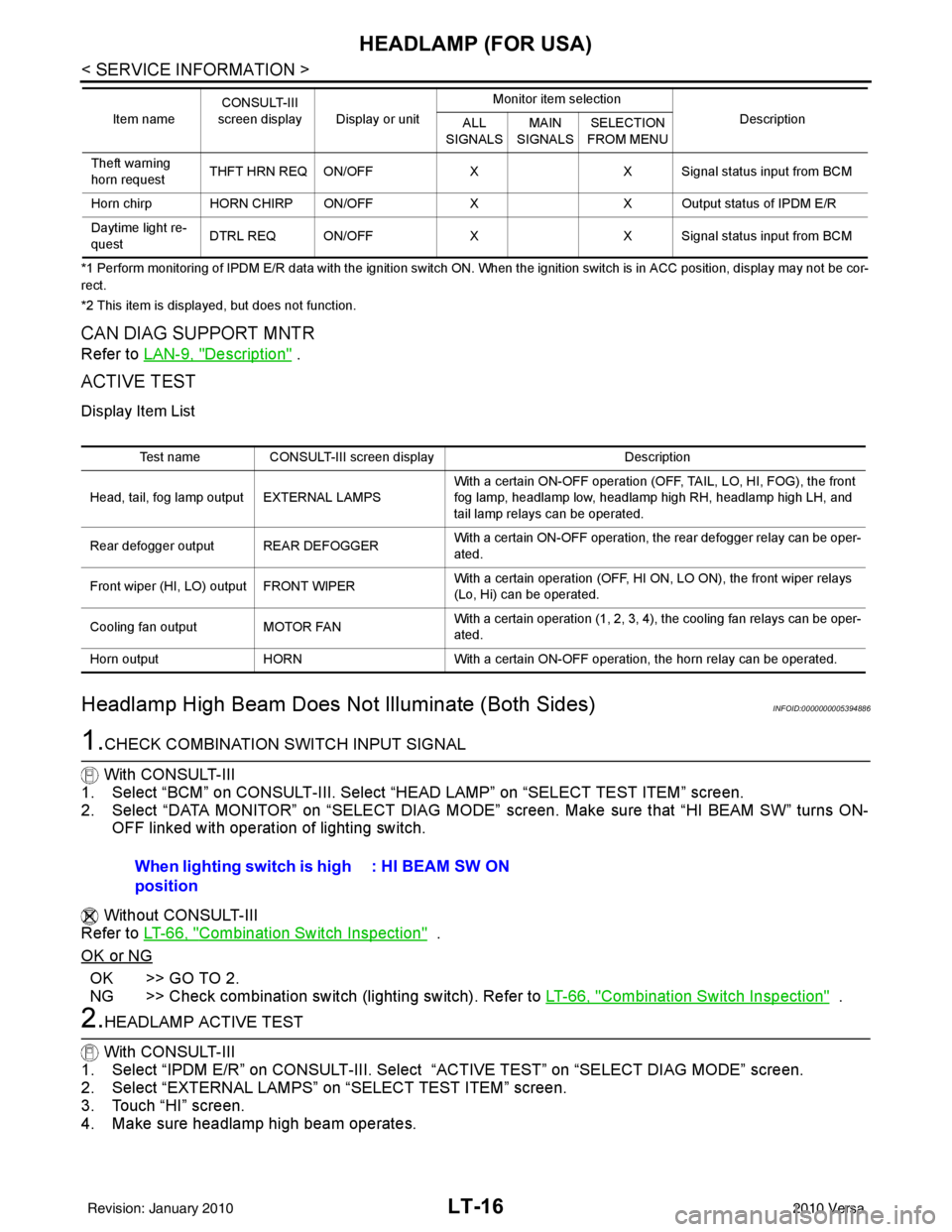
ACTIVE TEST
Display Item List
Headlamp High Beam Does No t Illuminate (Both Sides)INFOID:0000000005394886
1.CHECK COMBINATION SWITCH INPUT SIGNAL
With CONSULT-III
1. Select “BCM” on CONSULT-III. Select “HEAD LAMP” on “SELECT TEST ITEM” screen.
2. Select “DATA MONITOR” on “SELECT DIAG MODE” screen. Make sure that “HI BEAM SW” turns ON-
OFF linked with operation of lighting switch.
Without CONSULT-III
Refer to LT-66, "
Combination Switch Inspection" .
OK or NG
OK >> GO TO 2.
NG >> Check combination switch (lighting switch). Refer to LT-66, "
Combination Switch Inspection" .
2.HEADLAMP ACTIVE TEST
With CONSULT-III
1. Select “IPDM E/R” on CONSULT-III. Select “ACTIVE TEST” on “SELECT DIAG MODE” screen.
2. Select “EXTERNAL LAMPS” on “SELECT TEST ITEM” screen.
3. Touch “HI” screen.
4. Make sure headlamp high beam operates.
Theft warning
horn request THFT HRN REQ ON/OFF
XX Signal status input from BCM
Horn chirp HORN CHIRP ON/OFF XX Output status of IPDM E/R
Daytime light re-
quest DTRL REQ ON/OFF
XX Signal status input from BCM
Item name
CONSULT-III
screen display Display or unit Monitor item selection
Description
ALL
SIGNALS MAIN
SIGNALS SELECTION
FROM MENU
Test name CONSULT-III screen display Description
Head, tail, fog lamp output EXTERNAL LAMPS With a certain ON-OFF operation (OFF, TAIL, LO, HI, FOG), the front
fog lamp, headlamp low, headlamp high RH, headlamp high LH, and
tail lamp relays can be operated.
Rear defogger output REAR DEFOGGER With a certain ON-OFF operation, the rear defogger relay can be oper-
ated.
Front wiper (HI, LO) output FRONT WIPER With a certain operation (OFF, HI ON, LO ON), the front wiper relays
(Lo, Hi) can be operated.
Cooling fan output MOTOR FAN With a certain operation (1, 2, 3, 4), the cooling fan relays can be oper-
ated.
Horn output HORN With a certain ON-OFF operation, the horn relay can be operated.
When lighting switch is high
position : HI BEAM SW ON
Revision: January 20102010 Versa
Page 3015 of 3745

LT-20
< SERVICE INFORMATION >
HEADLAMP (FOR USA)
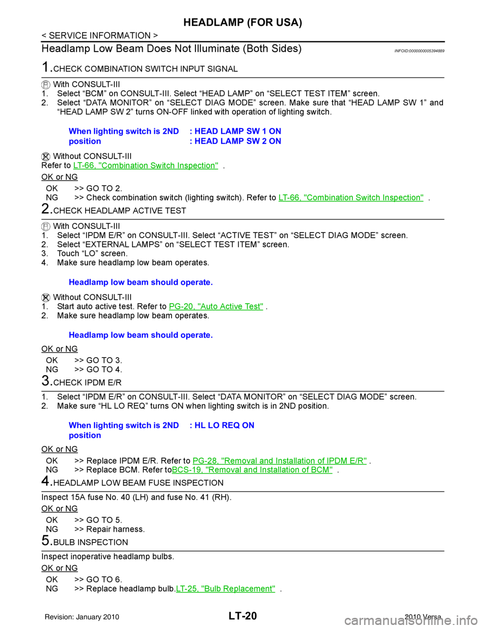
Headlamp Low Beam Does Not Illuminate (Both Sides)
INFOID:0000000005394889
1.CHECK COMBINATION SWITCH INPUT SIGNAL
With CONSULT-III
1. Select “BCM” on CONSULT-III. Select “HEAD LAMP” on “SELECT TEST ITEM” screen.
2. Select “DATA MONITOR” on “SELECT DIAG MODE” screen. Make sure that “HEAD LAMP SW 1” and
“HEAD LAMP SW 2” turns ON-OFF linked with operation of lighting switch.
Without CONSULT-III
Refer to LT-66, "
Combination Switch Inspection" .
OK or NG
OK >> GO TO 2.
NG >> Check combination switch (lighting switch). Refer to LT-66, "
Combination Switch Inspection" .
2.CHECK HEADLAMP ACTIVE TEST
With CONSULT-III
1. Select “IPDM E/R” on CONSULT-III. Select “ACTIVE TEST” on “SELECT DIAG MODE” screen.
2. Select “EXTERNAL LAMPS” on “SELECT TEST ITEM” screen.
3. Touch “LO” screen.
4. Make sure headlamp low beam operates.
Without CONSULT-III
1. Start auto active test. Refer to PG-20, "
Auto Active Test" .
2. Make sure headlamp low beam operates.
OK or NG
OK >> GO TO 3.
NG >> GO TO 4.
3.CHECK IPDM E/R
1. Select “IPDM E/R” on CONSULT-III. Select “DATA MONITOR” on “SELECT DIAG MODE” screen.
2. Make sure “HL LO REQ” turns ON when lighting switch is in 2ND position.
OK or NG
OK >> Replace IPDM E/R. Refer to PG-28, "Removal and Installation of IPDM E/R" .
NG >> Replace BCM. Refer to BCS-19, "
Removal and Installation of BCM" .
4.HEADLAMP LOW BEAM FUSE INSPECTION
Inspect 15A fuse No. 40 (LH) and fuse No. 41 (RH).
OK or NG
OK >> GO TO 5.
NG >> Repair harness.
5.BULB INSPECTION
Inspect inoperative headlamp bulbs.
OK or NG
OK >> GO TO 6.
NG >> Replace headlamp bulb. LT-25, "
Bulb Replacement" .
When lighting switch is 2ND
position
: HEAD LAMP SW 1 ON
: HEAD LAMP SW 2 ON
Headlamp low beam should operate.
Headlamp low beam should operate.
When lighting switch is 2ND
position: HL LO REQ ON
Revision: January 20102010 Versa