2010 NISSAN TIIDA low beam
[x] Cancel search: low beamPage 3061 of 3745
LT-66
< SERVICE INFORMATION >
COMBINATION SWITCH
Terminal and Reference Value for BCM
INFOID:0000000005394949
Refer to BCS-12, "Terminal and Reference Value for BCM" .
CONSULT-III Function (BCM)INFOID:0000000005394950
Refer to LT-13, "CONSULT-III Function (BCM)" .
Combination Switch InspectionINFOID:0000000005394951
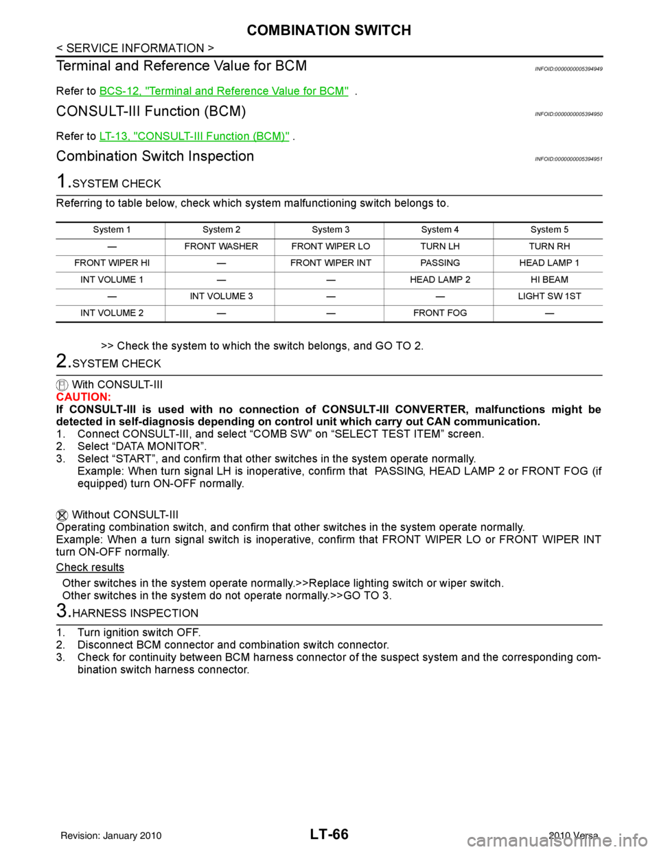
1.SYSTEM CHECK
Referring to table below, check which sy stem malfunctioning switch belongs to.
>> Check the system to which the switch belongs, and GO TO 2.
2.SYSTEM CHECK
With CONSULT-III
CAUTION:
If CONSULT-III is used with no connection of CONSULT-III CONVERTER, malfunctions might be
detected in self-diagnosis depending on cont rol unit which carry out CAN communication.
1. Connect CONSULT-III, and select “COM B SW” on “SELECT TEST ITEM” screen.
2. Select “DATA MONITOR”.
3. Select “START”, and confirm that other switches in the system operate normally.
Example: When turn signal LH is inoperative, confirm that PASSING, HEAD LAMP 2 or FRONT FOG (if
equipped) turn ON-OFF normally.
Without CONSULT-III
Operating combination switch, and confirm that other switches in the system operate normally.
Example: When a turn signal switch is inoperative, confirm that FRONT WIPER LO or FRONT WIPER INT
turn ON-OFF normally.
Check results
Other switches in the system operate normall y.>>Replace lighting switch or wiper switch.
Other switches in the system do not operate normally.>>GO TO 3.
3.HARNESS INSPECTION
1. Turn ignition switch OFF.
2. Disconnect BCM connector and combination switch connector.
3. Check for continuity between BCM harness connecto r of the suspect system and the corresponding com-
bination switch harness connector.
System 1 System 2System 3System 4 System 5
— FRONT WASHER FRONT WIPER LO TURN LHTURN RH
FRONT WIPER HI —FRONT WIPER INT PASSINGHEAD LAMP 1
INT VOLUME 1 ——HEAD LAMP 2 HI BEAM
— INT VOLUME 3 ——LIGHT SW 1ST
INT VOLUME 2 ——FRONT FOG —
Revision: January 20102010 Versa
Page 3402 of 3745
IPDM E/R (INTELLIGENT POWER DISTRIBUTION MODULE ENGINE ROOM)
PG-19
< SERVICE INFORMATION >
C
D E
F
G H
I
J
L
M A
B
PG
N
O P
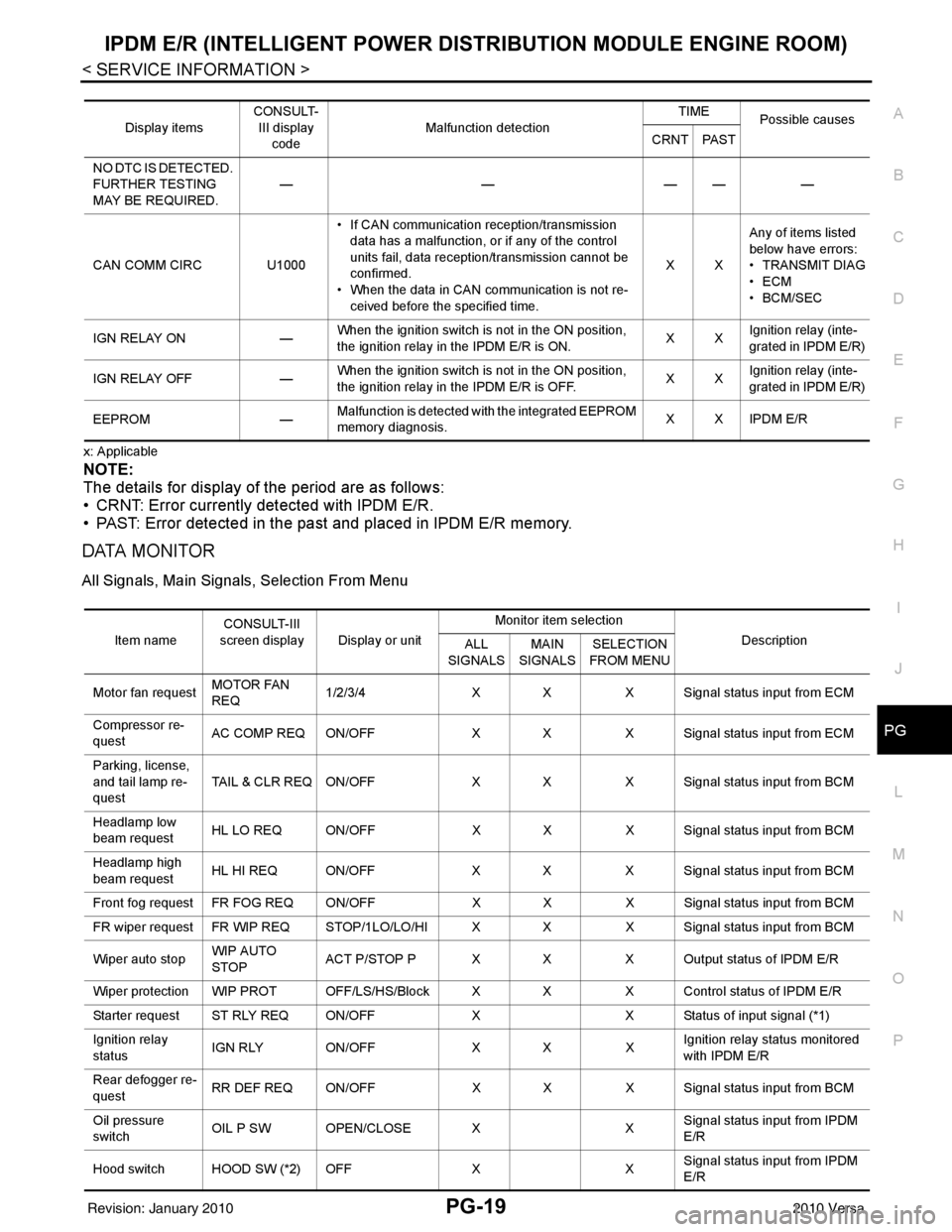
x: Applicable
NOTE:
The details for display of the period are as follows:
• CRNT: Error currently detected with IPDM E/R.
• PAST: Error detected in the past and placed in IPDM E/R memory.
DATA MONITOR
All Signals, Main Signals, Selection From Menu
Display items CONSULT-
III display code Malfunction detection TIME
Possible causes
CRNT PAST
NO DTC IS DETECTED.
FURTHER TESTING
MAY BE REQUIRED. ———
——
CAN COMM CIRC U1000 • If CAN communication reception/transmission
data has a malfunction, or if any of the control
units fail, data reception/transmission cannot be
confirmed.
• When the data in CAN communication is not re-
ceived before the specified time. XX
Any of items listed
below have
errors:
• TRANSMIT DIAG
•ECM
• BCM/SEC
IGN RELAY ON —When the ignition switch is not in the ON position,
the ignition relay in the IPDM E/R is ON. XX
Ignition relay (inte-
grated in IPDM E/R)
IGN RELAY OFF —When the ignition switch is not in the ON position,
the ignition relay in the IPDM E/R is OFF. XXIgnition relay (inte-
grated in IPDM E/R)
EEPROM —Malfunction is detected with the integrated EEPROM
memory diagnosis.
X X IPDM E/R
Item nameCONSULT-III
screen display Display or unit Monitor item selection
Description
ALL
SIGNALS MAIN
SIGNALS SELECTION
FROM MENU
Motor fan request MOTOR FAN
REQ1/2/3/4
X X X Signal status input from ECM
Compressor re-
quest AC COMP REQ ON/OFF
X XX Signal status input from ECM
Parking, license,
and tail lamp re-
quest TAIL & CLR REQ ON/OFF
X XX Signal status input from BCM
Headlamp low
beam request HL LO REQ ON/OFF
X XX Signal status input from BCM
Headlamp high
beam request HL HI REQ ON/OFF
X XX Signal status input from BCM
Front fog request FR FOG REQ ON/OFF X XX Signal status input from BCM
FR wiper request FR WIP REQ STOP/1LO/LO/HI X X X Signal status input from BCM
Wiper auto stop WIP AUTO
STOPACT P/STOP P X X
X Output status of IPDM E/R
Wiper protection WIP PROT OFF/LS/HS/Block X X X Control status of IPDM E/R
Starter request ST RLY REQ ON/OFF XX Status of input signal (*1)
Ignition relay
status IGN RLY ON/OFF
X XXIgnition relay status monitored
with IPDM E/R
Rear defogger re-
quest RR DEF REQ ON/OFF
X XX Signal status input from BCM
Oil pressure
switch OIL P SW OPEN/CLOSE X
XSignal status input from IPDM
E/R
Hood switch HOOD SW (*2) OFF XXSignal status input from IPDM
E/R
Revision: January 20102010 Versa
Page 3410 of 3745
IPDM E/R (INTELLIGENT POWER DISTRIBUTION MODULE ENGINE ROOM)
PG-27
< SERVICE INFORMATION >
C
D E
F
G H
I
J
L
M A
B
PG
N
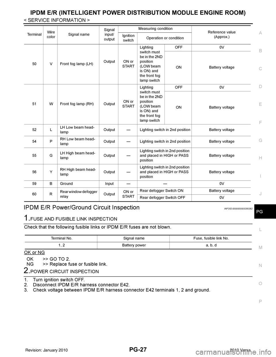
O PIPDM E/R Power/Ground Circuit InspectionINFOID:0000000005395362
1.FUSE AND FUSIBLE LINK INSPECTION
Check that the following fusible links or IPDM E/R fuses are not blown.
OK or NG
OK >> GO TO 2.
NG >> Replace fuse or fusible link.
2.POWER CIRCUIT INSPECTION
1. Turn ignition switch OFF.
2. Disconnect IPDM E/R harness connector E42.
3. Check voltage between IPDM E/R harness connector E42 terminals 1, 2 and ground.
50 V Front fog lamp (LH) Output ON or
STARTLighting
switch must
be in the 2ND
position
(LOW beam
is ON) and
the front fog
lamp switch OFF
0V
ON Battery voltage
51 W Front fog lamp (RH) Output ON or
START Lighting
switch must
be in the 2ND
position
(LOW beam
is ON) and
the front fog
lamp switch OFF
0V
ON Battery voltage
52 L LH Low beam head-
lamp Output — Lighting switch in 2nd position Battery voltage
54 P RH Low beam head-
lamp
Output — Lighting switch in 2nd position Battery voltage
55 G LH High beam head-
lamp
Output —Lighting switch in 2nd position
and placed in HIGH or PASS
position
Battery voltage
56 Y RH High beam head-
lamp Output —Lighting switch in 2nd position
and placed in HIGH or PASS
position Battery voltage
59 B Ground Input ——0V
60 R Rear window defogger
relay
OutputON or
START Rear defogger Switch ON
Battery voltage
Rear defogger Switch OFF 0V
Te r m i n a l
Wire
color Signal name Signal
input/
output Measuring condition
Reference value
(Approx.)
Ignition
switch Operation or condition
Terminal No.
Signal nameFuse, fusible link No.
1, 2 Battery power a, b, d
Revision: January 20102010 Versa
Page 3482 of 3745
RAX-6
< SERVICE INFORMATION >
WHEEL HUB
WHEEL HUB
On-Vehicle Inspection and ServiceINFOID:0000000005397139
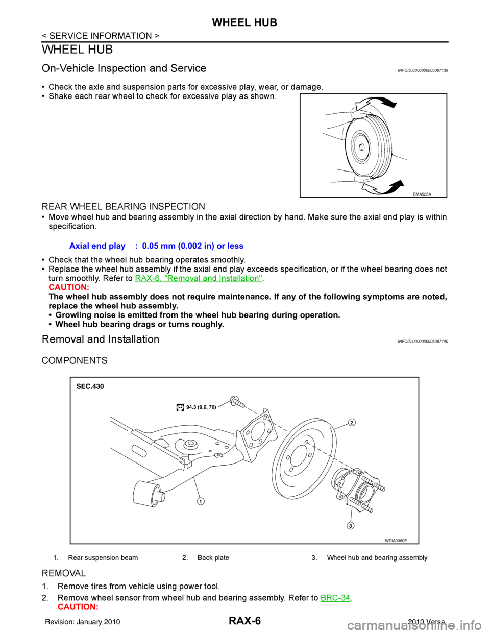
• Check the axle and suspension parts for excessive play, wear, or damage.
• Shake each rear wheel to check for excessive play as shown.
REAR WHEEL BEARING INSPECTION
• Move wheel hub and bearing assembly in the axial direction by hand. Make sure the axial end play is within
specification.
• Check that the wheel hub bearing operates smoothly.
• Replace the wheel hub assembly if the axial end play exceeds specification, or if the wheel bearing does not turn smoothly. Refer to RAX-6, "
Removal and Installation".
CAUTION:
The wheel hub assembly does not requ ire maintenance. If any of the following symptoms are noted,
replace the wheel hub assembly.
• Growling noise is emitted from the wheel hub bearing during operation.
• Wheel hub bearing drags or turns roughly.
Removal and InstallationINFOID:0000000005397140
COMPONENTS
REMOVAL
1. Remove tires from vehicle using power tool.
2. Remove wheel sensor from wheel hub and bearing assembly. Refer to BRC-34
.
CAUTION:
SMA525A
Axial end play : 0.05 mm (0.002 in) or less
1. Rear suspension beam 2. Back plate 3. Wheel hub and bearing assembly
WDIA0360E
Revision: January 20102010 Versa
Page 3520 of 3745
RSU-6
< SERVICE INFORMATION >
REAR SUSPENSION ASSEMBLY
REAR SUSPENSION ASSEMBLY
On-Vehicle Inspection and ServiceINFOID:0000000005397077
Make sure the mounting conditions (looseness, backlash) of each component and component conditions
(wear, damage) are within specifications.
SHOCK ABSORBER INSPECTION
Check shock absorber for oil leakage, damage and replace it if necessary.
Wheel AlignmentInspectionINFOID:0000000005397078
DESCRIPTION
Measure wheel alignment under unladen conditions.
NOTE:
“Unladen conditions” means that fuel, engine coolant, and lubricant are full. Spare tire, jack, hand tools and
mats are in designated positions.
PRELIMINARY
Check the following:
1. Tires for improper air pressure and wear.
2. Road wheels for runout. Refer to WT-6
.
3. Wheel bearing axial end play. Refer to RAX-6, "
On-Vehicle Inspection and Service" .
4. Shock absorber operation.
5. Each mounting part of suspension for looseness and deformation.
6. Rear suspension beam for cracks, deformation, and other damage.
7. Vehicle height (posture).
GENERAL INFORMATION AND RECOMMENDATIONS
1. A Four-Wheel Thrust Alignment should be performed. • This type of alignment is recommended for any NISSAN vehicle.
• The four-wheel “thrust” process helps ensure that the vehicle is properly aligned and the steering wheel
is centered.
• The alignment machine itself should be ca pable of accepting any NISSAN vehicle.
• The alignment machine should be checked to ensure that it is level.
2. Make sure the alignment machine is properly calibrated. • Your alignment machine should be regularly calibrated in order to give correct information.
• Check with the manufacturer of your specific al ignment machine for their recommended Service/Cali-
bration Schedule.
THE ALIGNMENT PROCESS
IMPORTANT: Use only the alignment specifications listed in this Service Manual. Refer to RSU-13, "Wheel
Alignment (Unladen*)" .
1. When displaying the alignment settings, many alignment machines use “indicators”: (Green/red, plus or minus, Go/No Go). Do NOT use these indicators.
• The alignment specifications programmed into your alignment machine that operate these indicators may not be correct.
• This may result in an ERROR.
2. Some newer alignment machines are equipped with an optional “Rolling Compensation” method to “com- pensate” the sensors (alignment targets or head units). Do NOT use this “Rolling Compensation”
method.
• Use the “Jacking Compensation” method. After inst alling the alignment targets or head units, raise the
vehicle and rotate the wheels 1/2 turn both ways.
• See Instructions in the alignment machine you are using for more information.
CAMBER INSPECTION
Revision: January 20102010 Versa
Page 3522 of 3745
RSU-8
< SERVICE INFORMATION >
REAR SUSPENSION ASSEMBLY
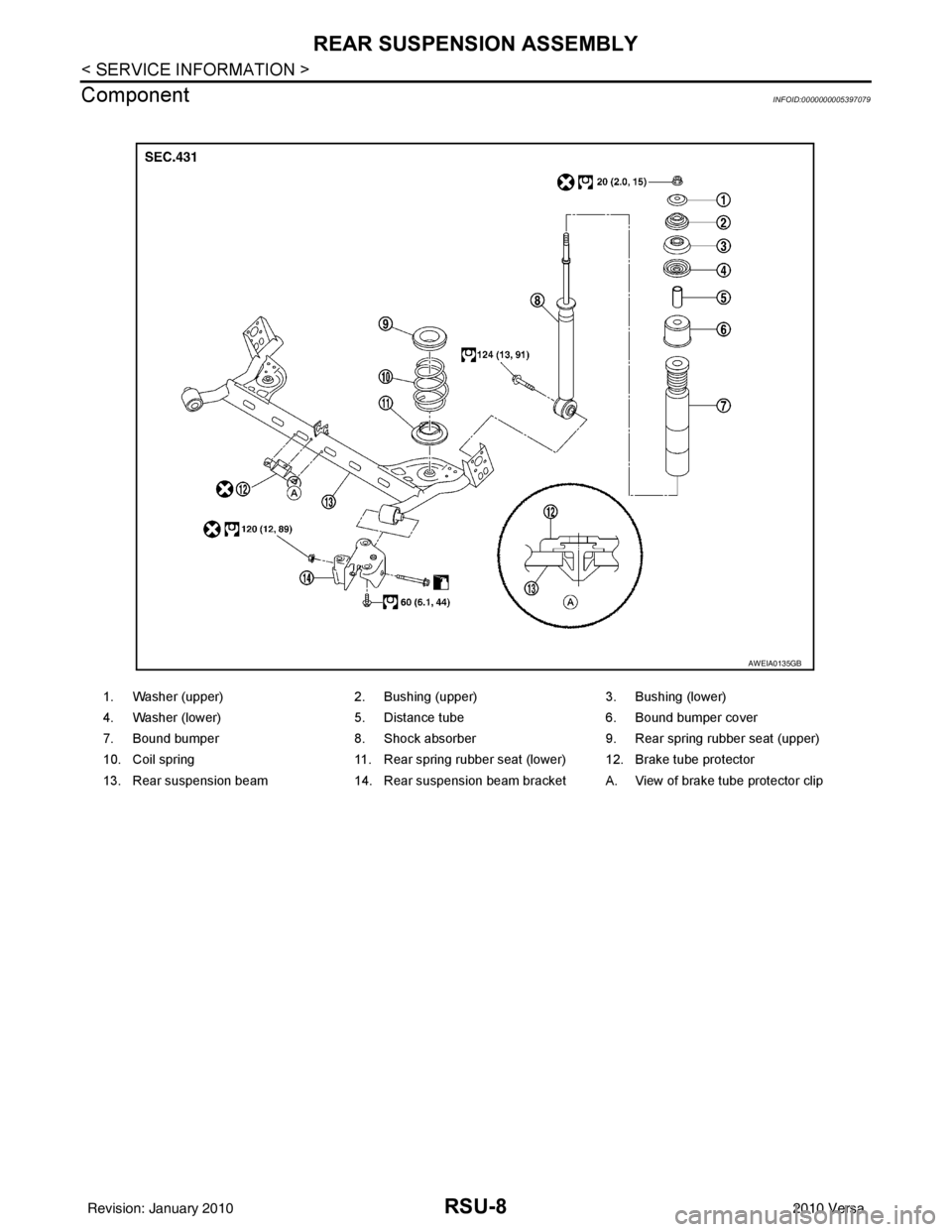
Component
INFOID:0000000005397079
1. Washer (upper) 2. Bushing (upper)3. Bushing (lower)
4. Washer (lower) 5. Distance tube6. Bound bumper cover
7. Bound bumper 8. Shock absorber 9. Rear spring rubber seat (upper)
10. Coil spring 11. Rear spring rubber seat (lower) 12. Brake tube protector
13. Rear suspension beam 14. Rear suspension beam bracket A. View of brake tube protector clip
AWEIA0135GB
Revision: January 20102010 Versa
Page 3523 of 3745
SHOCK ABSORBERRSU-9
< SERVICE INFORMATION >
C
DF
G H
I
J
K L
M A
B
RSU
N
O P
SHOCK ABSORBER
Removal and InstallationINFOID:0000000005397080
REMOVAL
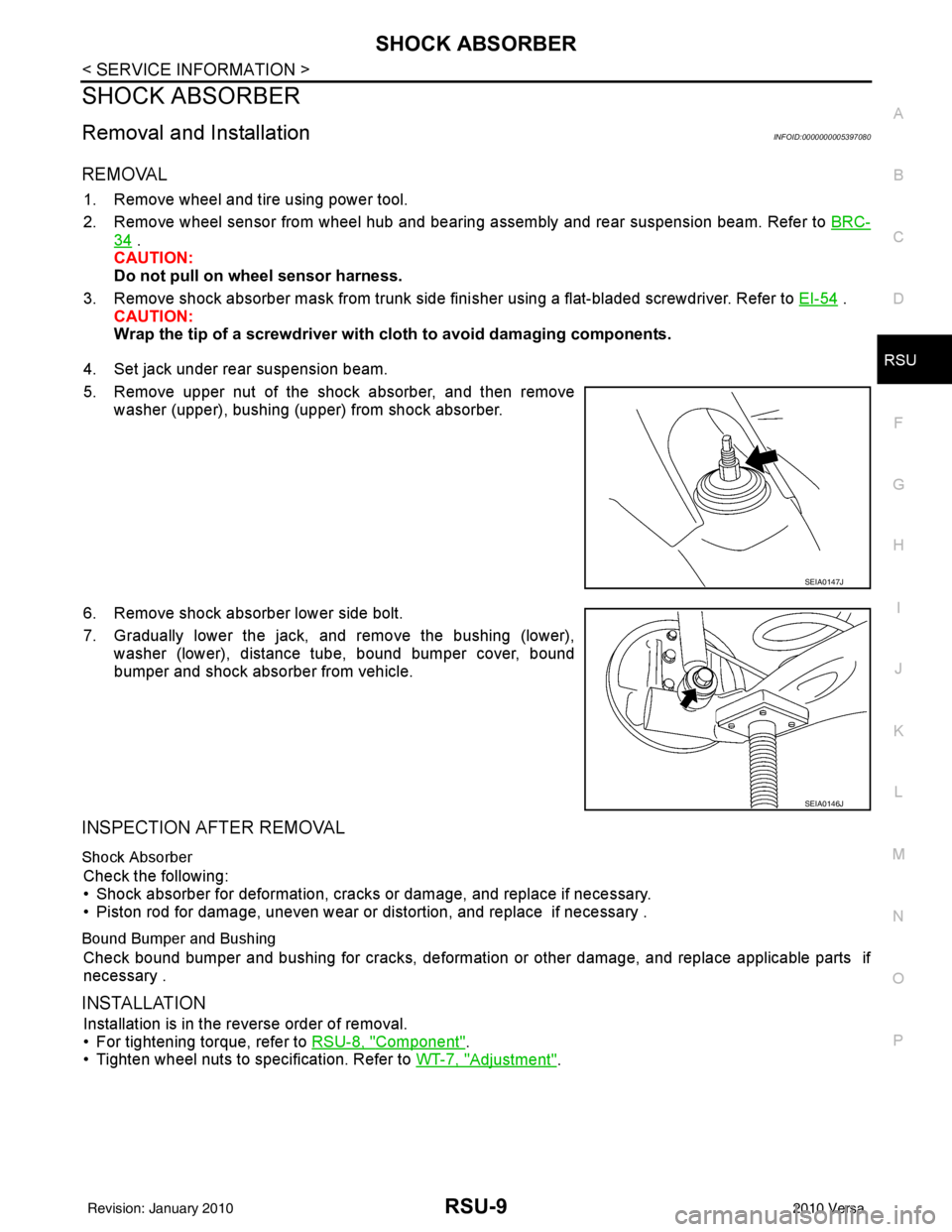
1. Remove wheel and tire using power tool.
2. Remove wheel sensor from wheel hub and bearing assembly and rear suspension beam. Refer to BRC-
34 .
CAUTION:
Do not pull on wheel sensor harness.
3. Remove shock absorber mask from trunk side fini sher using a flat-bladed screwdriver. Refer to EI-54
.
CAUTION:
Wrap the tip of a screwdriver with cl oth to avoid damaging components.
4. Set jack under rear suspension beam.
5. Remove upper nut of the shock absorber, and then remove washer (upper), bushing (upper) from shock absorber.
6. Remove shock absorber lower side bolt.
7. Gradually lower the jack, and remove the bushing (lower), washer (lower), distance tube, bound bumper cover, bound
bumper and shock absorber from vehicle.
INSPECTION AFTER REMOVAL
Shock Absorber
Check the following:
• Shock absorber for deformation, cracks or damage, and replace if necessary.
• Piston rod for damage, uneven wear or distortion, and replace if necessary .
Bound Bumper and Bushing
Check bound bumper and bushing for cracks, deformation or other damage, and replace applicable parts if
necessary .
INSTALLATION
Installation is in the reverse order of removal.
• For tightening torque, refer to RSU-8, "
Component".
• Tighten wheel nuts to specification. Refer to WT-7, "
Adjustment".
SEIA0147J
SEIA0146J
Revision: January 20102010 Versa
Page 3525 of 3745
COIL SPRINGRSU-11
< SERVICE INFORMATION >
C
DF
G H
I
J
K L
M A
B
RSU
N
O P
COIL SPRING
Removal and InstallationINFOID:0000000005397081
REMOVAL
1. Remove wheel and tire using power tool.
2. Remove wheel sensor from wheel hub and bearing assembly. Refer to BRC-34, "
Removal and Installa-
tion".
CAUTION:
Do not pull on wheel sensor harness.
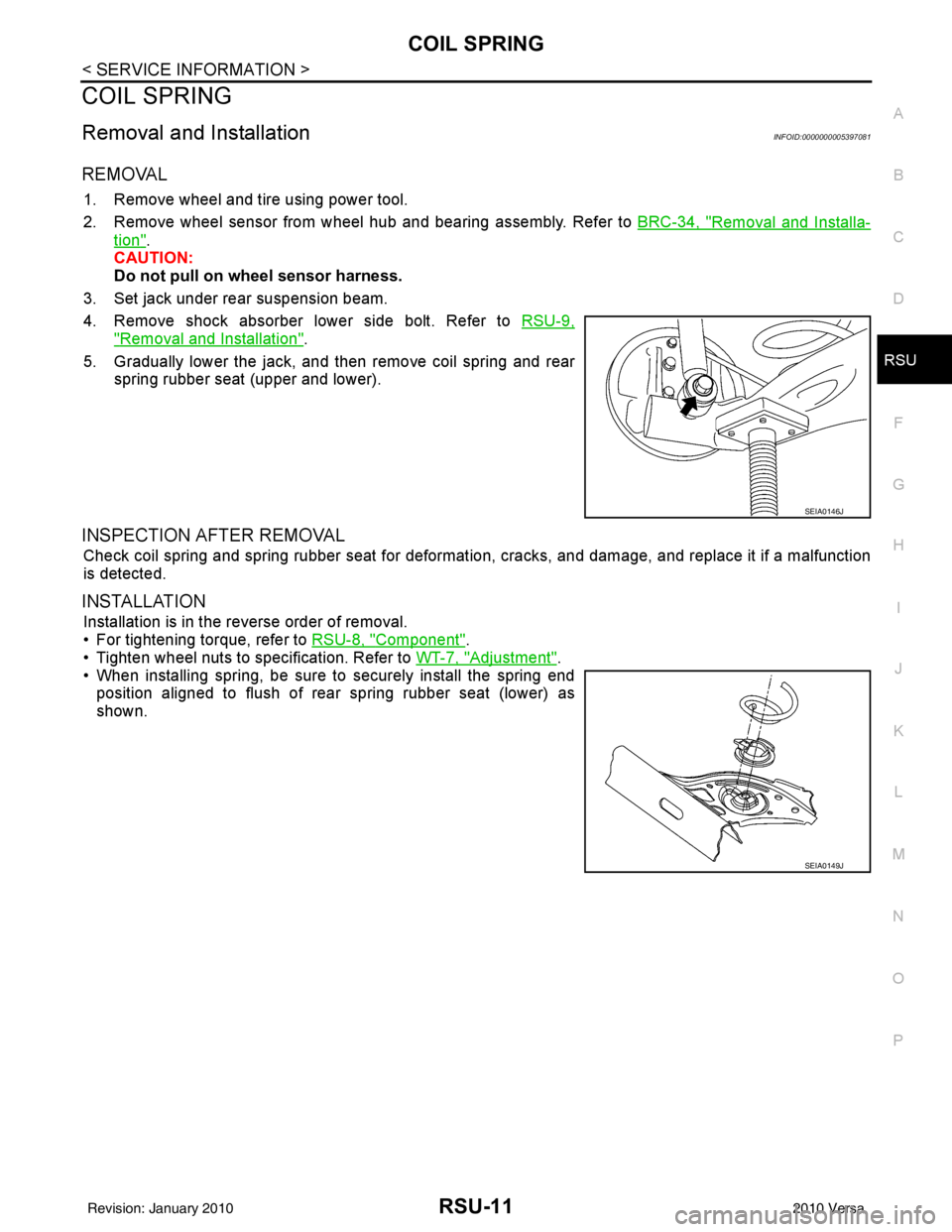
3. Set jack under rear suspension beam.
4. Remove shock absorber lower side bolt. Refer to RSU-9,
"Removal and Installation".
5. Gradually lower the jack, and then remove coil spring and rear spring rubber seat (upper and lower).
INSPECTION AFTER REMOVAL
Check coil spring and spring rubber seat for deformation, cracks, and damage, and replace it if a malfunction
is detected.
INSTALLATION
Installation is in the reverse order of removal.
• For tightening torque, refer to RSU-8, "
Component".
• Tighten wheel nuts to specification. Refer to WT-7, "
Adjustment".
• When installing spring, be sure to securely install the spring end position aligned to flush of rear spring rubber seat (lower) as
shown.
SEIA0146J
SEIA0149J
Revision: January 20102010 Versa