2010 MERCEDES-BENZ C350S ESP
[x] Cancel search: ESPPage 217 of 364
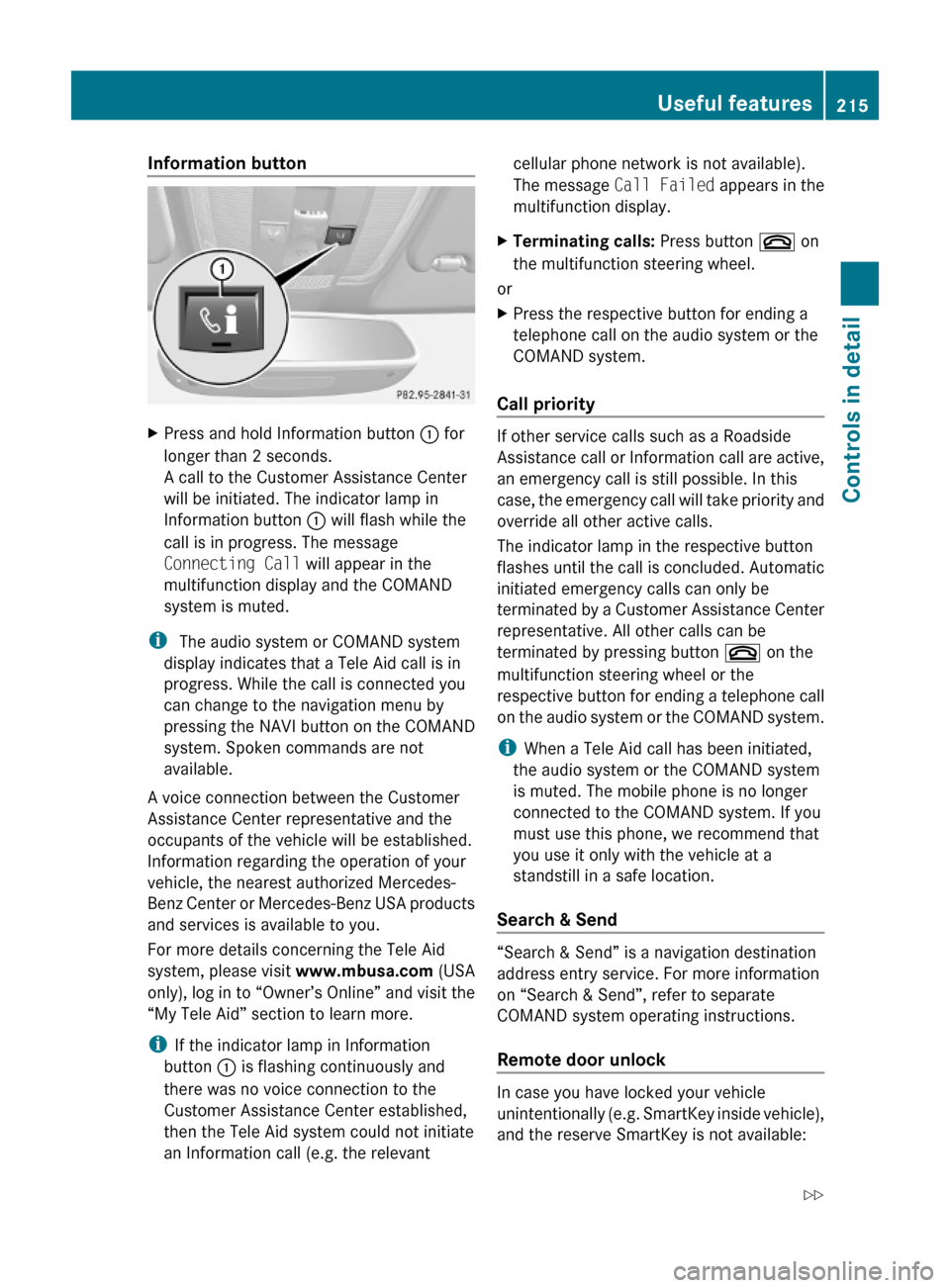
Information button XPress and hold Information button : for
longer than 2 seconds.
A call to the Customer Assistance Center
will be initiated. The indicator lamp in
Information button : will flash while the
call is in progress. The message
Connecting Call will appear in the
multifunction display and the COMAND
system is muted.
i The audio system or COMAND system
display indicates that a Tele Aid call is in
progress. While the call is connected you
can change to the navigation menu by
pressing the NAVI button on the COMAND
system. Spoken commands are not
available.
A voice connection between the Customer
Assistance Center representative and the
occupants of the vehicle will be established.
Information regarding the operation of your
vehicle, the nearest authorized Mercedes-
Benz Center or Mercedes-Benz USA products
and services is available to you.
For more details concerning the Tele Aid
system, please visit www.mbusa.com (USA
only), log in to “Owner’s Online” and visit the
“My Tele Aid” section to learn more.
iIf the indicator lamp in Information
button : is flashing continuously and
there was no voice connection to the
Customer Assistance Center established,
then the Tele Aid system could not initiate
an Information call (e.g. the relevant
cellular phone network is not available).
The message Call Failed appears in the
multifunction display.
XTerminating calls: Press button ~ on
the multifunction steering wheel.
or
XPress the respective button for ending a
telephone call on the audio system or the
COMAND system.
Call priority
If other service calls such as a Roadside
Assistance call or Information call are active,
an emergency call is still possible. In this
case, the emergency call will take priority and
override all other active calls.
The indicator lamp in the respective button
flashes until the call is concluded. Automatic
initiated emergency calls can only be
terminated by a Customer Assistance Center
representative. All other calls can be
terminated by pressing button ~ on the
multifunction steering wheel or the
respective button for ending a telephone call
on the audio system or the COMAND system.
iWhen a Tele Aid call has been initiated,
the audio system or the COMAND system
is muted. The mobile phone is no longer
connected to the COMAND system. If you
must use this phone, we recommend that
you use it only with the vehicle at a
standstill in a safe location.
Search & Send
“Search & Send” is a navigation destination
address entry service. For more information
on “Search & Send”, refer to separate
COMAND system operating instructions.
Remote door unlock
In case you have locked your vehicle
unintentionally (e.g. SmartKey inside vehicle),
and the reserve SmartKey is not available:
Useful features215Controls in detail204_AKB; 5; 23, en-USd2ureepe,Version: 2.11.8.12009-07-16T17:54:06+02:00 - Seite 215Z
Page 219 of 364
and reverse features as required by U.S.
federal safety standards (this includes any
garage door opener model manufactured
before April 1, 1982). A garage door that
cannot detect an object - signaling the door
to stop and reverse - does not meet current
U.S. federal safety standards.
When programming a garage door opener,
park vehicle outside the garage.
Do not run the engine while programming the
integrated remote control. Inhalation of
exhaust gas is hazardous to your health. All
exhaust gas contains carbon monoxide (CO),
and inhaling it can cause unconsciousness
and possible death.
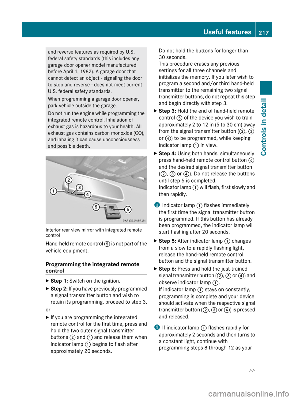
Interior rear view mirror with integrated remotecontrol
Hand-held remote control A is not part of the
vehicle equipment.
Programming the integrated remote
control
XStep 1: Switch on the ignition.XStep 2: If you have previously programmed
a signal transmitter button and wish to
retain its programming, proceed to step 3.
or
XIf you are programming the integrated
remote control for the first time, press and
hold the two outer signal transmitter
buttons ; and ? and release them when
indicator lamp : begins to flash after
approximately 20 seconds.
Do not hold the buttons for longer than
30 seconds.
This procedure erases any previous
settings for all three channels and
initializes the memory. If you later wish to
program a second and/or third hand-held
transmitter to the remaining two signal
transmitter buttons, do not repeat this step
and begin directly with step 3.
XStep 3: Hold the end of hand-held remote
control A of the device you wish to train
approximately 2 to 12 in (5 to 30 cm) away
from the signal transmitter button (;, =
or ?) to be programmed, while keeping
indicator lamp : in view.
XStep 4: Using both hands, simultaneously
press hand-held remote control button B
and the desired signal transmitter button
(;, = or ?). Do not release the buttons
until step 5 is completed.
Indicator lamp : will flash, first slowly and
then rapidly.
iIndicator lamp : flashes immediately
the first time the signal transmitter button
is programmed. If this button has already
been programmed, the indicator lamp will
start flashing after 20 seconds.
XStep 5: After indicator lamp : changes
from a slow to a rapidly flashing light,
release the hand-held remote control
button and the signal transmitter button.
XStep 6: Press and hold the just-trained
signal transmitter button (;, = or ?) and
observe indicator lamp :.
If indicator lamp : stays on constantly,
programming is complete and your device
should activate when the respective signal
transmitter button (;, = or ?) is pressed
and released.
iIf indicator lamp : flashes rapidly for
approximately 2 seconds and then turns to
a constant light, continue with
programming steps 8 through 12 as your
Useful features217Controls in detail204_AKB; 5; 23, en-USd2ureepe,Version: 2.11.8.12009-07-16T17:54:06+02:00 - Seite 217Z
Page 221 of 364
control, or simply for continued use as a
hand-held remote control to operate the
respective device in other situations.
Reprogramming a single signal
transmitter button
To program a device using a signal
transmitter button previously trained, follow
these steps:
XSwitch on the ignition.XPress and hold the desired signal
transmitter button ( ;, = or ?). Do not
release the button.
Indicator lamp : will begin to flash after
20 seconds.XWithout releasing the signal transmitter
button, proceed with programming starting
with step 3.
Operation of integrated remote control
XSwitch on the ignition.XSelect and press the appropriate
integrated signal transmitter button ( ;,
= or ?) to activate the remote controlled
device.
The integrated remote control transmitter
continues to send the signal as long as the
button is pressed – up to 20 seconds.
Erasing the integrated remote control
memory
i If you sell your vehicle, erase the codes of
all three channels.
XSwitch on the ignition.XSimultaneously press and hold outer signal
transmitter buttons ; and ?, for
approximately 20 seconds, until indicator
lamp : flashes rapidly. Do not hold for
longer than 30 seconds.
The codes of all three channels are erased.Programming tips
If you are having difficulty programming the
integrated remote control, here are some
helpful tips:
R Check the frequency of hand-held remote
control A (typically located on the reverse
side of the remote). The integrated remote
control is compatible with radio-frequency
devices operating between 280-390 MHz.
R Put a new battery in hand-held remote
control A. This will increase the likelihood
of the hand-held remote control sending a
stronger and more accurate signal to the
integrated remote control.
R While performing step 3, hold hand-held
remote control A at different lengths and
angles from the signal transmitter button
( ; , = or ?) you are programming.
Attempt varying angles at the distance of 2
to 12 inches (5 to 30 cm) away or the same
angle at varying distances.
R If another hand-held remote control is
available for the same device, try the
programming steps again using that other
hand-held remote control. Make sure new
batteries are in the hand-held remote
control before beginning the procedure.
R Straighten the antenna wire from the
garage door opener assembly. This may
help improve transmitting and/or receiving
signals.
i Certain types of garage door openers are
incompatible with the integrated remote
control. If you should experience further
difficulties with programming the
integrated remote control, contact an
authorized Mercedes-Benz Center, or call
the Mercedes-Benz Customer Assistance
Center (USA only) at
1-800-FOR-MERCedes (1-800-367-6372),
or the HomeLink ®
Hotline (USA only) at
1-800-355-3515, or the Customer Service
(Canada only) at 1-800-387-0100.
Useful features219Controls in detail204_AKB; 5; 23, en-USd2ureepe,Version: 2.11.8.12009-07-16T17:54:06+02:00 - Seite 219Z
Page 235 of 364
Tire and Loading Information placard on the
driver’s door B-pillar ( Y page 238). If
necessary, add air to achieve the
recommended tire inflation pressure.XIf you have overfilled the tire, release tire
inflation pressure by pushing the metal
stem of the valve with e.g. a tip of a pen.
Then recheck the tire inflation pressure
with the tire gauge.XInstall the valve cap.XRepeat this procedure for each tire.
Tire pressure loss warning system
(Canada only)
While the vehicle is being driven, the tire
pressure loss warning system monitors the
set tire inflation pressures by evaluating each
wheel’s rotational speed. This allows the
system to detect a significant loss of pressure
in a tire. If a wheel’s rotational speed changes
due to falling tire inflation pressure, you will
see a corresponding warning message in the
multifunction display.
The tire pressure loss warning system may
function in a restricted manner or with a delay
R when snow chains are mounted to the
vehicle
R in the presence of ice and snow
R when you are driving on a loose surface
(e.g. sand or gravel)
R when you are driving in a very sporty
manner (involving rapid acceleration or
high speeds in curves)
R when you are driving with a loaded roof
rack or heavily laden vehicle
GWarning!
When the multifunction display shows the
message Check Tire Pressure Soon , one
or more of your tires are significantly
underinflated. You should stop and check
your tires as soon as possible, and inflate
them to the proper tire inflation pressure as
indicated on the vehicle’s Tire and Loading
Information placard or, if available, on the tire
inflation pressure label.
Driving on a significantly underinflated tire
causes the tire to overheat and can lead to
tire failure. Underinflation also reduces fuel
efficiency and tire tread life, and may affect
the vehicle’s handling and stopping ability.
Each tire, including the spare, should be
checked at least once a month when cold.
Inflate the tires to the recommended tire
inflation pressure as specified on
R the Tire and Loading Information placard on
the driver’s door B-pillar
or
R the tire inflation pressure label located on
the inside of the fuel filler flap
i The recommended tire inflation pressures
for your vehicle can be found on
R the Tire and Loading Information placard
located on the driver’s door B-pillar
( Y page 238)
R the tire inflation pressure label on the
inside of the fuel filler flap
The tire inflation pressures are not listed in
the Operator’s Manual.GWarning!
The tire pressure loss warning system does
not provide a warning for wrongly selected tire
inflation pressures. Always adjust tire
inflation pressure according to the Tire and
Loading Information placard on the driver’s
door B-pillar or on the tire inflation pressure
label located on the inside of the fuel filler flap.
The tire pressure loss warning system does
not replace regular checks of the tire inflation
pressures since a gradual pressure loss in
more than one tire cannot be detected by the
tire pressure loss warning system.
The tire pressure loss warning system is not
able to issue a warning due to a sudden
dramatic loss of tire inflation pressure (e.g.
Tires and wheels233Operation204_AKB; 5; 23, en-USd2ureepe,Version: 2.11.8.12009-07-16T17:54:06+02:00 - Seite 233Z
Page 237 of 364

The TPMS only functions on wheels that are
equipped with the proper electronic sensors.GWarning!
The TPMS does not indicate a warning for
wrongly selected inflation pressures. Always
adjust tire inflation pressure according to the
Tire and Loading Information placard or the
supplemental tire inflation pressure
information on the inside of the fuel filler flap.
The TPMS is not able to issue a warning due
to a sudden dramatic loss of pressure (e.g. tire
blowout caused by a foreign object). In this
case bring the vehicle to a halt by carefully
applying the brakes and avoiding abrupt
steering maneuvers.
GWarning!
Each tire, including the spare (if provided),
should be checked at least once a month
when cold and inflated to the inflation
pressure recommended by the vehicle
manufacturer on the Tire and Loading
Information placard on the driver’s door B-
pillar or the tire inflation pressure label on the
inside of the fuel filler flap. If your vehicle has
tires of a different size than the size indicated
on the Tire and Loading Information placard
or the tire inflation pressure label, you should
determine the proper tire inflation pressure
for those tires.
As an added safety feature, your vehicle has
been equipped with a tire pressure monitoring
system (TPMS) that illuminates a low tire
pressure telltale when one or more of your
tires are significantly underinflated.
Accordingly, when the low tire pressure
telltale illuminates, you should stop and check
your tires as soon as possible, and inflate
them to the proper pressure. Driving on a
significantly underinflated tire causes the tire
to overheat and can lead to tire failure.
Underinflation also reduces fuel efficiency
and tire tread life, and may affect the vehicle’s
handling and stopping ability. Please note that
the TPMS is not a substitute for proper tire
maintenance, and it is the driver’s
responsibility to maintain correct tire
pressure, even if underinflation has not
reached the level to trigger illumination of the
TPMS low tire pressure telltale.
Your vehicle has also been equipped with a
TPMS malfunction indicator to indicate when
the system is not operating properly. The
TPMS malfunction indicator is combined with
the low tire pressure telltale. When the
system detects a malfunction, the telltale will
flash for approximately 1 minute and then
remain continuously illuminated. This
sequence will continue upon subsequent
vehicle start-ups as long as the malfunction
exists. When the malfunction indicator is
illuminated, the system may not be able to
detect or signal low tire pressure as intended.
TPMS malfunctions may occur for a variety of
reasons, including the installation of
incompatible replacement or alternate tires
or wheels on the vehicle that prevent the
TPMS from functioning properly. Always
check the TPMS malfunction telltale after
replacing one or more tires or wheels on your
vehicle to ensure that the replacement or
alternate tires and wheels allow the TPMS to
continue to function properly.
i If a condition causing the TPMS to
malfunction develops, it may take up to
10 minutes for the system to signal a
malfunction using the TPMS telltale
flashing and illumination sequence.
The telltale extinguishes after a few
minutes driving if the malfunction has been
corrected.
Tire pressure inquiries are made using the
multifunction display. The current tire
inflation pressure for each tire appears in the
multifunction display after a few minutes of
driving.
i Possible differences between the
readings of a tire pressure gauge of an air
hose, e.g. gas station equipment, and the
vehicle’s control system can occur. The tireTires and wheels235Operation204_AKB; 5; 23, en-USd2ureepe,Version: 2.11.8.12009-07-16T17:54:06+02:00 - Seite 235Z
Page 238 of 364
pressure displayed by the control system
apply to sea level. In high-altitude
locations, the reading on a tire pressure
gauge will be higher than the reading issued
by the vehicle’s control system. Do not
reduce the tire inflation pressure under
such circumstances.
XSwitch on the ignition.XPress button = or ; on the
multifunction steering wheel to select the
Service menu (Y page 129).
XPress button 9 or : to select Tire
Pressure.
XPress button a.
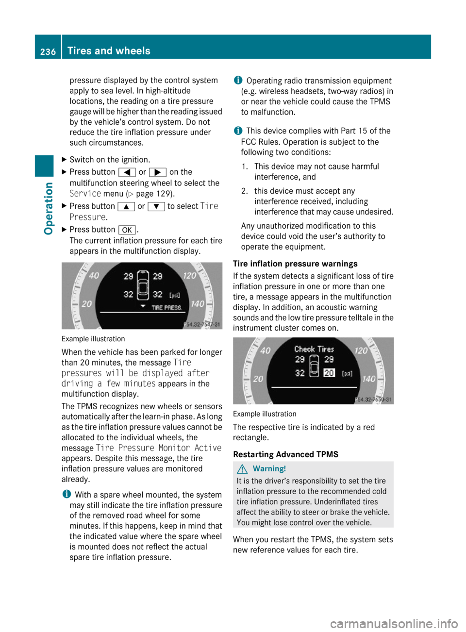
The current inflation pressure for each tire
appears in the multifunction display.
Example illustration
When the vehicle has been parked for longer
than 20 minutes, the message Tire
pressures will be displayed after
driving a few minutes appears in the
multifunction display.
The TPMS recognizes new wheels or sensors
automatically after the learn-in phase. As long
as the tire inflation pressure values cannot be
allocated to the individual wheels, the
message Tire Pressure Monitor Active
appears. Despite this message, the tire
inflation pressure values are monitored
already.
iWith a spare wheel mounted, the system
may still indicate the tire inflation pressure
of the removed road wheel for some
minutes. If this happens, keep in mind that
the indicated value where the spare wheel
is mounted does not reflect the actual
spare tire inflation pressure.
iOperating radio transmission equipment
(e.g. wireless headsets, two-way radios) in
or near the vehicle could cause the TPMS
to malfunction.
iThis device complies with Part 15 of the
FCC Rules. Operation is subject to the
following two conditions:
1. This device may not cause harmful
interference, and
2. this device must accept any
interference received, including
interference that may cause undesired.
Any unauthorized modification to this
device could void the user’s authority to
operate the equipment.
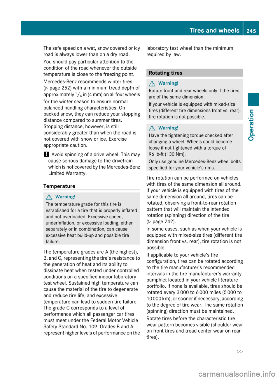
Tire inflation pressure warnings
If the system detects a significant loss of tire
inflation pressure in one or more than one
tire, a message appears in the multifunction
display. In addition, an acoustic warning
sounds and the low tire pressure telltale in the
instrument cluster comes on.
Example illustration
The respective tire is indicated by a red
rectangle.
Restarting Advanced TPMS
GWarning!
It is the driver’s responsibility to set the tire
inflation pressure to the recommended cold
tire inflation pressure. Underinflated tires
affect the ability to steer or brake the vehicle.
You might lose control over the vehicle.
When you restart the TPMS, the system sets
new reference values for each tire.
236Tires and wheelsOperation
204_AKB; 5; 23, en-USd2ureepe,Version: 2.11.8.12009-07-16T17:54:06+02:00 - Seite 236
Page 247 of 364
The safe speed on a wet, snow covered or icy
road is always lower than on a dry road.
You should pay particular attention to the
condition of the road whenever the outside
temperature is close to the freezing point.
Mercedes-Benz recommends winter tires
( Y page 252) with a minimum tread depth of
approximately 1
/ 6 in (4 mm) on all four wheels
for the winter season to ensure normal
balanced handling characteristics. On
packed snow, they can reduce your stopping
distance compared to summer tires.
Stopping distance, however, is still
considerably greater than when the road is
not covered with snow or ice. Exercise
appropriate caution.
! Avoid spinning of a drive wheel. This may
cause serious damage to the drivetrain
which is not covered by the Mercedes-Benz
Limited Warranty.
Temperature GWarning!
The temperature grade for this tire is
established for a tire that is properly inflated
and not overloaded. Excessive speed,
underinflation, or excessive loading, either
separately or in combination, can cause
excessive heat build-up and possible tire
failure.
The temperature grades are A (the highest),
B, and C, representing the tire’s resistance to
the generation of heat and its ability to
dissipate heat when tested under controlled
conditions on a specified indoor laboratory
test wheel. Sustained high temperature can
cause the material of the tire to degenerate
and reduce tire life, and excessive
temperature can lead to sudden tire failure.
The grade C corresponds to a level of
performance which all passenger car tires
must meet under the Federal Motor Vehicle
Safety Standard No. 109. Grades B and A
represent higher levels of performance on the
laboratory test wheel than the minimum
required by law.
Rotating tires
GWarning!
Rotate front and rear wheels only if the tires
are of the same dimension.
If your vehicle is equipped with mixed-size
tires (different tire dimensions front vs. rear),
tire rotation is not possible.
GWarning!
Have the tightening torque checked after
changing a wheel. Wheels could become
loose if not tightened with a torque of
96 lb-ft (130 Nm).
Only use genuine Mercedes-Benz wheel bolts
specified for your vehicle’s rims.
Tire rotation can be performed on vehicles
with tires of the same dimension all around.
If your vehicle is equipped with tires of the
same dimension all around, tires can be
rotated, observing a front-to-rear rotation
pattern that will maintain the intended
rotation (spinning) direction of the tire
( Y page 242).
In some cases, such as when your vehicle is
equipped with mixed-size tires (different tire
dimension front vs. rear), tire rotation is not
possible.
If applicable to your vehicle’s tire
configuration, tires can be rotated according
to the tire manufacturer’s recommended
intervals in the tire manufacturer’s warranty
pamphlet located in your vehicle literature
portfolio. If none is available, tires should be
rotated every 3 000 to 6 000 miles (5 000 to
10 000 km), or sooner if necessary, according
to the degree of tire wear. The same rotation
(spinning) direction must be maintained.
Rotate tires before the characteristic tire
wear pattern becomes visible (shoulder wear
on front tires and tread center wear on rear
tires).
Tires and wheels245Operation204_AKB; 5; 23, en-USd2ureepe,Version: 2.11.8.12009-07-16T17:54:06+02:00 - Seite 245Z
Page 249 of 364
Letter “T” preceding the size designation:
Temporary spare tires which are high
pressure compact spares designed for
temporary emergency use only.
Tire width
Tire width : indicates the nominal tire width
in millimeters.
Aspect ratio
Aspect ratio ; is the dimensional
relationship between tire section height and
section width and is expressed in percentage.
The aspect ratio is arrived at by dividing
section height by section width.
Tire code
Tire code = indicates the tire construction
type. The “R” stands for radial tire type. Letter
“D” means diagonal or bias ply construction;
letter “B” means belted-bias ply construction.
At the tire manufacturer’s option, any tire
with a speed capability above 149 mph
(240 km/h) can include a “ZR” in the size
designation (for example: 245/40 ZR 18). For
additional information, see “Tire speed
rating” ( Y page 247).
Rim diameter
Rim diameter ? is the diameter of the bead
seat, not the diameter of the rim edge. The
rim diameter is indicated in inches (in).
Load indexGWarning!
The tire load rating must always be at least
half of the GAWR of your vehicle. Otherwise,
tire failure may be the result which may cause
an accident and/or serious injury to you or
others.
Always replace rims and tires with the same
designation, manufacturer and type as shown
on the original part.
GWarning!
Do not overload the tires by exceeding the
specified load limit as indicated on the Tire
and Loading Information placard on the
driver’s door B-pillar. Overloading the tires
can overheat them, possibly causing a
blowout. Overloading the tires can also result
in handling or steering problems, or brake
failure.
Load index A is a numerical code associated
with the maximum load a tire can support.
For example, a load rating of 91 corresponds
to a maximum load of 1356 lb (615 kg) the
tire is designed to support. See also
“Maximum tire load” (Y page 242) where the
maximum load associated with the load index
is indicated in kilograms and lbs.
For additional information on the load index,
see “Load identification” ( Y page 249).
Speed symbol GWarning!
Even when permitted by law, never operate a
vehicle at speeds greater than the maximum
speed rating of the tires.
Exceeding the maximum speed for which tires
are rated can lead to sudden tire failure,
causing loss of vehicle control and possibly
resulting in an accident and/or serious
personal injury and possible death, for you
and for others.
Regardless of the tire speed rating, local
speed limits should be obeyed. Use prudent
driving speeds appropriate to prevailing
conditions.
Speed symbol B indicates the approved
maximum speed (tire speed rating) for the
tire.
Summer tires
IndexSpeed ratingQup to 100 mph (160 km/h)Rup to 106 mph (170 km/h)Sup to 112 mph (180 km/h)Tup to 118 mph (190 km/h)Tires and wheels247Operation204_AKB; 5; 23, en-USd2ureepe,Version: 2.11.8.12009-07-16T17:54:06+02:00 - Seite 247Z