2010 JAGUAR XFR list
[x] Cancel search: listPage 35 of 3039
Trustmark Authoring Standards (TAS) Repair Procedur
NOTE: TAS style procedures can be identified by steps that have no accompanying step text and the magenta color of the
electrical connectors and fasteners such as nuts, bolts, clamps or clips.
A TAS removal and installation procedure uses a sequence of color illustrations to indicate the order to be followed when
removing/disassembling or installing/assembling a component.
Many of the TAS procedures will have the installation information within the removal steps. These procedures will have the
following note at the beginning of the procedure:
NOTE: Removal steps in this procedure may contain installation details.
Reuse of fasteners and seals and gaskets
The following list details the general policy for the reuse of fasteners and seals and gaskets.
Types of self-locking nuts and bolts
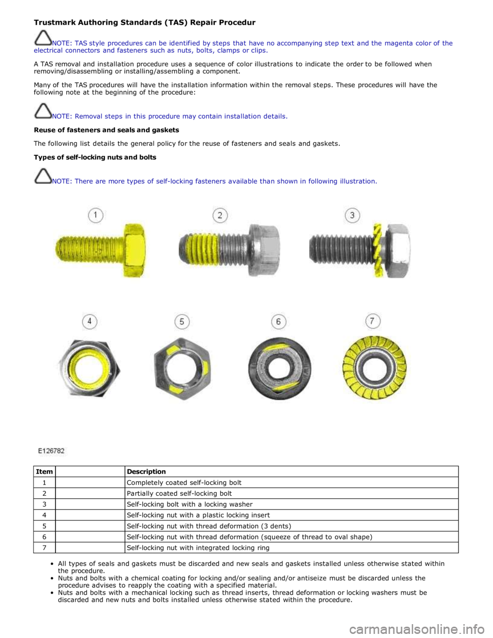
NOTE: There are more types of self-locking fasteners available than shown in following illustration.
Item
Description 1
Completely coated self-locking bolt 2
Partially coated self-locking bolt 3
Self-locking bolt with a locking washer 4
Self-locking nut with a plastic locking insert 5
Self-locking nut with thread deformation (3 dents) 6
Self-locking nut with thread deformation (squeeze of thread to oval shape) 7
Self-locking nut with integrated locking ring
All types of seals and gaskets must be discarded and new seals and gaskets installed unless otherwise stated within
the procedure.
Nuts and bolts with a chemical coating for locking and/or sealing and/or antiseize must be discarded unless the
procedure advises to reapply the coating with a specified material.
Nuts and bolts with a mechanical locking such as thread inserts, thread deformation or locking washers must be
discarded and new nuts and bolts installed unless otherwise stated within the procedure.
Page 56 of 3039
General Information - Health and Safety Precautions
Description and Operation Published: 11-May-2011
The Health and Safety Precautions subsection refers to some commonly used chemicals and materials, hazards associated with
their use, and safety measures to be taken. Some of these chemicals may be included in the following list either in their own
right or as an ingredient in a sealer or adhesive.
Acids and Alkalis
See also Battery Acids.
e.g. caustic soda, sulphuric acid.
Used in batteries and cleaning materials.
Irritant and corrosive to the skin, eyes, nose and throat. Cause burns. Can destroy ordinary protective clothing.
Avoid splashes to the skin, eyes and clothing. Wear suitable protective impervious apron, gloves and goggles. Do not breath
mists.
Ensure access to eye wash bottles, shower and soap are readily available for splashing accidents.
Display Eye Hazard sign.
Air Bags
See also Fire, Chemical Materials - General
Highly flammable, explosive – observe No Smoking policy.
Used as a part of the Supplemental Restraint System (SRS), mounted in various positions around the vehicle.
The inflator contains a high-energetic propellant which, when ignited, produces a VERY HOT GAS (2500° C).
The gas generant used in air bags is Sodium Azide. This material is hermetically sealed in the module and is completely
consumed during deployment. No attempt should be made to open an air bag inflator as this will lead to the risk of exposure
to Sodium Azide. If a gas generator is ruptured, full protective clothing should be worn when dealing with the spillage.
After normal deployment, gloves and safety goggles should be worn during the handling process.
Deployed air bags should be disposed of in a plastic bag in accordance with local regulations at an approved chemical waste
site.
Following any direct contact with gas generant.
Wash affected areas thoroughly with water
Seek medical assistance if necessary
WARNING: To avoid accidental deployment and possible personal injury, the backup power supply must be depleted
before repairing or replacing any SRS components. To deplete the backup power supply energy, disconnect the battery negative
cable and wait for one minute. Failure to follow this instruction may result in personal injury.
NOTE: The storage, transportation, disposal and/or recycling of air bag modules must be carried out in accordance with all
applicable federal, state and local regulations including, but not limited to, those governing building and fire codes,
environmental protection, occupational health and safety and transportation.
Air Bags - Do's
Do store in an air bag safe when not installed to the vehicle.
Do store modules in an upright position
Do keep modules dry
Do carry modules with the cover side pointing away from the body
Do place modules with their cover side upwards
Do carefully inspect modules for damage
Do stand to one side when connecting modules
Do make sure all test equipment is properly calibrated and maintained
Do wash you hands after handling deployed air bags
Do wear safety glasses when carrying out repairs to the SRS or when handling an air bag module
Only carry out a system test with the air bag modules fully installed
Do inspect the condition of the impact sensor mounting bracket and sensor flylead if the vehicle has been involved in
an impact. Replace if damaged, even if there has been no deployment.
Air Bags - Do Nots
Do not store highly flammable material together with modules or gas generators
Do not store gas generators at temperatures exceeding 80° C
Page 75 of 3039
WARNINGS:
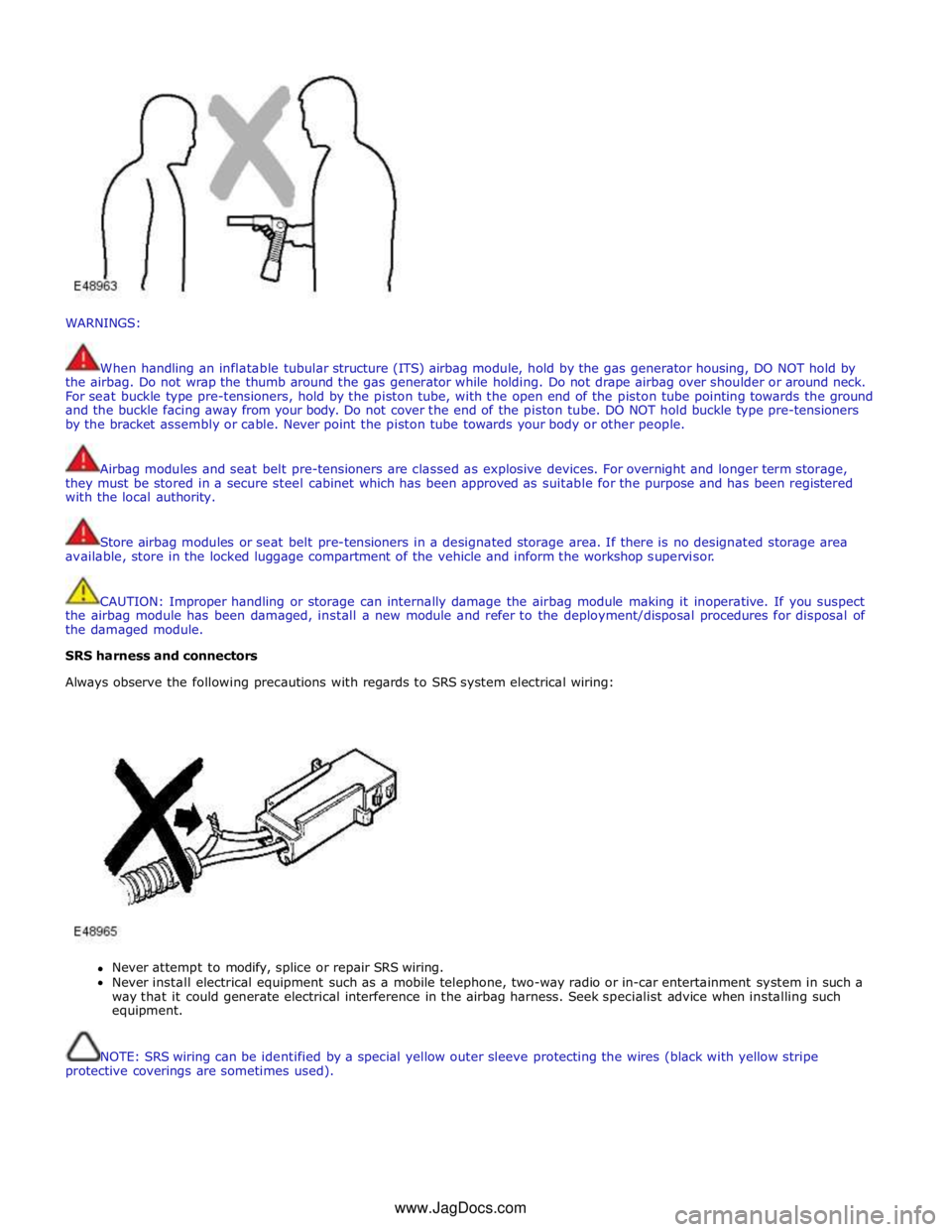
When handling an inflatable tubular structure (ITS) airbag module, hold by the gas generator housing, DO NOT hold by
the airbag. Do not wrap the thumb around the gas generator while holding. Do not drape airbag over shoulder or around neck.
For seat buckle type pre-tensioners, hold by the piston tube, with the open end of the piston tube pointing towards the ground
and the buckle facing away from your body. Do not cover the end of the piston tube. DO NOT hold buckle type pre-tensioners
by the bracket assembly or cable. Never point the piston tube towards your body or other people.
Airbag modules and seat belt pre-tensioners are classed as explosive devices. For overnight and longer term storage,
they must be stored in a secure steel cabinet which has been approved as suitable for the purpose and has been registered
with the local authority.
Store airbag modules or seat belt pre-tensioners in a designated storage area. If there is no designated storage area
available, store in the locked luggage compartment of the vehicle and inform the workshop supervisor.
CAUTION: Improper handling or storage can internally damage the airbag module making it inoperative. If you suspect
the airbag module has been damaged, install a new module and refer to the deployment/disposal procedures for disposal of
the damaged module.
SRS harness and connectors
Always observe the following precautions with regards to SRS system electrical wiring:
Never attempt to modify, splice or repair SRS wiring.
Never install electrical equipment such as a mobile telephone, two-way radio or in-car entertainment system in such a
way that it could generate electrical interference in the airbag harness. Seek specialist advice when installing such
equipment.
NOTE: SRS wiring can be identified by a special yellow outer sleeve protecting the wires (black with yellow stripe
protective coverings are sometimes used). www.JagDocs.com
Page 106 of 3039
Published: 17-Apr-2014
General Information - Diagnostic Trouble Code (DTC) Index DTC: Adaptive
Damping Module (SUMB)
Description and Operation
Adaptive Damping Module (SUMB)
CAUTION: Diagnosis by substitution from a donor vehicle is NOT acceptable. Substitution of control modules does not
guarantee confirmation of a fault, and may also cause additional faults in the vehicle being tested and/or the donor vehicle
NOTES:
If the control module or a component is suspect and the vehicle remains under manufacturer warranty, refer to the
warranty policy and procedures manual, or determine if any prior approval programme is in operation, prior to the installation
of a new module/component
Generic scan tools may not read the codes listed, or may read only 5-digit codes. Match the 5 digits from the scan tool to
the first 5 digits of the 7-digit code listed to identify the fault (the last 2 digits give extra information read by the
manufacturer-approved diagnostic system)
When performing voltage or resistance tests, always use a digital multimeter accurate to three decimal places and with a
current calibration certificate. When testing resistance, always take the resistance of the digital multimeter leads into account
Check and rectify basic faults before beginning diagnostic routines involving pinpoint tests
Inspect connectors for signs of water ingress, and pins for damage and/or corrosion
If diagnostic trouble codes are recorded and, after performing the pinpoint tests, a fault is not present, an intermittent
concern may be the cause. Always check for loose connections and corroded terminals
Where an 'on demand self-test' is referred to, this can be accessed via the 'diagnostic trouble code monitor' tab on the
manufacturers approved diagnostic system
Check DDW for open campaigns. Refer to the corresponding bulletins and SSMs which may be valid for the specific
customer complaint and carry out the recommendations as required
he table below lists all diagnostic trouble codes (DTCs) that could be logged in the adaptive damping module, for additional
diagnosis and testing information refer to the relevant diagnosis and testing section
For additional information, refer to: Vehicle Dynamic Suspension (204-05 Vehicle Dynamic Suspension, Diagnosis and Testing).
DTC Description Possible Causes Action C101D-12
Left Front
vertical
acceleration
sensor - Short
to power
Left Front vertical
acceleration sensor
circuit short to power
Refer to the electrical circuit diagrams and check left front
vertical acceleration sensor circuit for short to power or
another circuit. Repair circuit, clear the DTC and retest the
system C101D-14
Left Front
vertical
acceleration
sensor - Short
to ground, open
circuit
Left Front vertical
acceleration sensor
circuit short to
ground, open circuit
Vertical acceleration
sensor fault
Refer to the electrical circuit diagrams and check front vertical
acceleration sensor circuit for short to ground, open circuit. If
no fault found on wiring suspect sensor. Replace sensor, clear
DTC and retest the system C101D-22
Left Front
vertical
acceleration
sensor - Signal
amplitude >
maximum
Left front vertical
acceleration sensor
insecurely mounted
Left front vertical
acceleration sensor
signal circuit short to
another circuit
Left front vertical
acceleration sensor
With vehicle parked on a level surface, read Left Front Vertical
Accelerometer voltage and check it lies in range 1.9 to 2.1
volts. If not OK then check electrical wiring for shorts, loose
connections and repair as required. If wiring OK then suspect
faulty sensor/incorrectly fitted sensor. Check the sensor is
correctly mounted, secure or replace sensor as required. Refer
to the new module/component installation note at the top of
the DTC Index, clear DTC and retest system
Page 120 of 3039
Published: 17-Apr-2014
General Information - Diagnostic Trouble Code (DTC) Index DTC: Anti-Lock Braking System (ABS)
Description and Operation
Anti-Lock Braking System (ABS)
CAUTION: Diagnosis by substitution from a donor vehicle is NOT acceptable. Substitution of control modules does not
guarantee confirmation of a fault, and may also cause additional faults in the vehicle being tested and/or the donor vehicle
NOTES:
If the control module or a component is suspect and the vehicle remains under manufacturer warranty, refer to the
warranty policy and procedures manual, or determine if any prior approval programme is in operation, prior to the installation
of a new module/component
Generic scan tools may not read the codes listed, or may read only 5-digit codes. Match the 5 digits from the scan tool to
the first 5 digits of the 7-digit code listed to identify the fault (the last 2 digits give extra information read by the
manufacturer-approved diagnostic system)
When performing voltage or resistance tests, always use a digital multimeter accurate to three decimal places and with a
current calibration certificate. When testing resistance, always take the resistance of the digital multimeter leads into account
Check and rectify basic faults before beginning diagnostic routines involving pinpoint tests
Inspect connectors for signs of water ingress, and pins for damage and/or corrosion
If diagnostic trouble codes are recorded and, after performing the pinpoint tests, a fault is not present, an intermittent
concern may be the cause. Always check for loose connections and corroded terminals
Where an 'on demand self-test' is referred to, this can be accessed via the 'diagnostic trouble code monitor' tab on the
manufacturers approved diagnostic system
Check DDW for open campaigns. Refer to the corresponding bulletins and SSMs which may be valid for the specific
customer complaint and carry out the recommendations as required
The table below lists all Diagnostic Trouble Codes (DTCs) that could be logged in the anti-lock braking system module, for
additional diagnosis and testing information refer to the relevant Diagnosis and Testing Section.
For additional information, refer to: Anti-Lock Control - Stability Assist (206-09 Anti-Lock Control - Stability Assist, Diagnosis
and Testing).
DTC Description Possible Causes Action C0021-09
Brake Booster
Performance -
Component Failures
No vacuum available from
engine due to split/leaking
hose etc
Brake booster servo has
failed due to lack of vacuum
Check integrity of brake booster vacuum hose.
Check and install a new brake booster as required C0030-38
Left Front Tone
Wheel - Signal
frequency incorrect
Left front magnetic pulse
ring damaged/contaminated
Incorrect component
installed
Sensor internal fault
Check the left front magnetic pulse ring for damage
or contamination. Clean or replace as required. If no
damage/contamination found, suspect wheel speed
sensor. Refer to the Warranty Policy and Procedures
manual if a module/component is suspect. To
validate the repair and extinguish the lamps, the
vehicle needs to be driven above 9mph/15kph for
more than 10 seconds C0031-12
Left Front Wheel
Speed Sensor -
Short to battery
Electrical wiring harness
fault
Sensor internal fault
Refer to the electrical circuit diagrams and check the
wheel speed sensor circuit for short to power. Repair
harness as required. If no harness fault found,
suspect wheel speed sensor. Refer to the Warranty
Policy and Procedures manual if a www.JagDocs.com
Page 125 of 3039

Published: 12-May-2014
General Information - Diagnostic Trouble Code (DTC) Index DTC: Audio Amplifier Module (AAM)
Description and Operation
Audio Amplifier Module (AAM)
CAUTION: Diagnosis by substitution from a donor vehicle is NOT acceptable. Substitution of control modules does not
guarantee confirmation of a fault, and may also cause additional faults in the vehicle being tested and/or the donor vehicle.
NOTES:
If a control module or a component is suspect and the vehicle remains under manufacturer warranty, refer to the Warranty
Policy and Procedures manual, or determine if any prior approval programme is in operation, prior to the installation of a new
module/component.
Generic scan tools may not read the codes listed, or may read only 5-digit codes. Match the 5 digits from the scan tool to
the first 5 digits of the 7-digit code listed to identify the fault (the last 2 digits give extra information read by the
manufacturer-approved diagnostic system).
When performing voltage or resistance tests, always use a digital multimeter accurate to three decimal places, and with
an up-to-date calibration certificate. When testing resistance always take the resistance of the digital multimeter leads into
account.
Check and rectify basic faults before beginning diagnostic routines involving pinpoint tests.
Inspect connectors for signs of water ingress, and pins for damage and/or corrosion.
If DTCs are recorded and, after performing the pinpoint tests, a fault is not present, an intermittent concern may be the
cause. Always check for loose connections and corroded terminals.
Check DDW for open campaigns. Refer to the corresponding bulletins and SSMs which may be valid for the specific
customer complaint and carry out the recommendations as required.
The table below lists all Diagnostic Trouble Codes (DTCs) that could be logged in the Audio Amplifier Module (AAM). For
additional diagnosis and testing information, refer to the relevant Diagnosis and Testing section in the workshop manual.
For additional information, refer to: Information and Entertainment System (415-00 Information and Entertainment System - General Information, Diagnosis and Testing).
DTC Description Possible Causes Action B1A01-11
Speaker #1 - Circuit
short to ground
Front left tweeter or
mid-range speaker
circuit - Short to
ground
Refer to electrical circuit diagrams and check front left
tweeter speaker circuit for short to ground B1A01-12
Speaker #1 - Circuit
short to battery
Front left tweeter or
mid-range speaker
circuit - Short to
power
Refer to electrical circuit diagrams and check front left
tweeter speaker circuit for short to power B1A01-13
Speaker #1 - Circuit
open
Front left tweeter or
mid-range speaker
circuit - Open circuit
Refer to electrical circuit diagrams and check front left
tweeter speaker circuit for open circuit B1A01-1A
Speaker #1 - Circuit
resistance below
threshold
Front left tweeter or
mid-range speaker
circuit - Resistance
below threshold
Carry out any pinpoint tests associated with this DTC
using the manufacturer approved diagnostic system www.JagDocs.com
Page 131 of 3039

Published: 17-Apr-2014
General Information - Diagnostic Trouble Code (DTC) Index DTC: Blind Spot Monitoring System Module (SODL/SODR)
Description and Operation
Blind Spot Monitoring System Module (SODL/SODR)
CAUTION: Diagnosis by substitution from a donor vehicle is NOT acceptable. Substitution of control modules does not
guarantee confirmation of a fault and may also cause additional faults in the vehicle being checked and/or the donor vehicle.
NOTES:
If the control module or a component is suspect and the vehicle remains under manufacturer warranty, refer to the
Warranty Policy and Procedures manual, or determine if any prior approval programme is in operation, prior to the installation
of a new module/component.
Generic scan tools may not read the codes listed, or may read only 5-digit codes. Match the 5 digits from the scan tool to
the first 5 digits of the 7-digit code listed to identify the fault (the last 2 digits give extra information read by the
manufacturer approved diagnostic system).
When performing voltage or resistance tests, always use a digital multimeter (DMM) accurate to three decimal places,
and with an up-to-date calibration certificate. When testing resistance, always take the resistance of the DMM leads into
account.
Check and rectify basic faults before beginning diagnostic routines involving pinpoint tests.
If DTCs are recorded and, after performing the pinpoint tests a fault is not present, an intermittent concern may be the
cause. Always check for loose connections and corroded terminals.
Where an 'on demand self-test' is referred to, this can be accessed via the 'DTC Monitor' tab on the manufacturers
approved diagnostic system.
Check DDW for open campaigns. Refer to the corresponding bulletins and SSMs which may be valid for the specific
customer complaint and carry out the recommendations as required.
The table below lists all Diagnostic Trouble Codes (DTCs) that could be logged in the Blind Spot Monitoring System Module, for
additional Diagnosis and Testing information refer to the relevant Diagnosis and Testing Section.
For additional information, refer to: Warning Devices (413-09 Warning Devices, Diagnosis and Testing).
DTC Description Possible Causes Action B11C9-11
Driver Display Status
LED - Circuit short to
ground
Circuit short to ground
Refer to the electrical circuit diagrams and check
driver display status LED circuit for short to
ground B11C9-15
Driver Display Status
LED - Circuit short to
battery or open
Circuit short to power or
open circuit
Refer to the electrical circuit diagrams and check
driver display status LED circuit for short to
ground B11D6-11
Driver Display Alert LED -
Circuit short to ground
Circuit short to ground
Refer to the electrical circuit diagrams and check
driver display status LED circuit for short to
ground B11D6-15
Driver Display Alert LED -
Circuit short to battery
or open
Circuit short to power or
open circuit
Refer to the electrical circuit diagrams and check
driver display status LED circuit for short to
ground U0010-00
Medium Speed CAN
Communication Bus - No
sub type information
No sub type information
Refer to the electrical circuit diagrams and check
the power and ground connections to the module.
Using the manufacturer approved diagnostic
system, complete a CAN network integrity test.
Refer to the electrical circuit diagrams and check
Page 134 of 3039

Published: 12-May-2014
General Information - Diagnostic Trouble Code (DTC) Index DTC: Central Junction Box (CJB)
Description and Operation
Central Junction Box (CJB)
CAUTION: Diagnosis by substitution from a donor vehicle is NOT acceptable. Substitution of control modules does not
guarantee confirmation of a fault, and may also cause additional faults in the vehicle being tested and/or the donor vehicle.
NOTES:
If a control module or a component is suspect and the vehicle remains under manufacturer warranty, refer to the Warranty
Policy and Procedures manual, or determine if any prior approval programme is in operation, prior to the installation of a new
module/component.
Generic scan tools may not read the codes listed, or may read only 5-digit codes. Match the 5 digits from the scan tool to
the first 5 digits of the 7-digit code listed to identify the fault (the last 2 digits give extra information read by the
manufacturer-approved diagnostic system).
When performing voltage or resistance tests, always use a digital multimeter accurate to three decimal places, and with
an up-to-date calibration certificate. When testing resistance always take the resistance of the digital multimeter leads into
account.
Check and rectify basic faults before beginning diagnostic routines involving pinpoint tests.
Inspect connectors for signs of water ingress, and pins for damage and/or corrosion.
If DTCs are recorded and, after performing the pinpoint tests, a fault is not present, an intermittent concern may be the
cause. Always check for loose connections and corroded terminals.
Check DDW for open campaigns. Refer to the corresponding bulletins and SSMs which may be valid for the specific
customer complaint and carry out the recommendations as required.
The table below lists all Diagnostic Trouble Codes (DTCs) that could be logged in the Central Junction Box (CJB). For additional
diagnosis and testing information, refer to the relevant Diagnosis and Testing section in the workshop manual.
For additional information, refer to: Communications Network (418-00 Module Communications Network, Diagnosis and Testing).
DTC Description Possible Causes Action B00D5-11
Restraint System
Passenger Disable
Indicator - Circuit
short to ground
PAD lamp supply circuit -
short to ground
Refer to the electrical circuit diagrams and check
PAD lamp supply circuit for short to ground B00D5-12
Restraint System
Passenger Disable
Indicator - Circuit
short to battery
PAD lamp supply circuit -
short to power
Refer to the electrical circuit diagrams and check
PAD lamp supply circuit for short to power B00D5-13
Restraint System
Passenger Disable
Indicator - Circuit open
PAD lamp supply circuit -
open circuit
Refer to the electrical circuit diagrams and check
PAD lamp supply circuit for open circuit B1009-51 Ignition Authorisation
- Not programmed
Faulty instrument cluster
Target SID
re-synchronisation error
following programming
CAN fault
Check ignition, power and ground supplies to CJB
and instrument cluster. Re-synchronize ID by
re-configuring the instrument cluster as a new
module. Check CAN communications between
instrument cluster and tester B1009-62 Ignition Authorisation
- Signal compare
failure
Low speed CAN fault
CJB fault
Instrument cluster fault
Incorrect module installed
(CJB/Instrument cluster)
Target SID synchronisation
Check CAN communications between CJB and
instrument cluster. Check ignition, power and
ground supplies to CJB and instrument cluster.
Confirm correct module is installed.
Re-synchronise ID by re-configuring the
instrument cluster as a new module. Check CAN