2010 JAGUAR XFR Replace Battery
[x] Cancel search: Replace BatteryPage 2336 of 3039
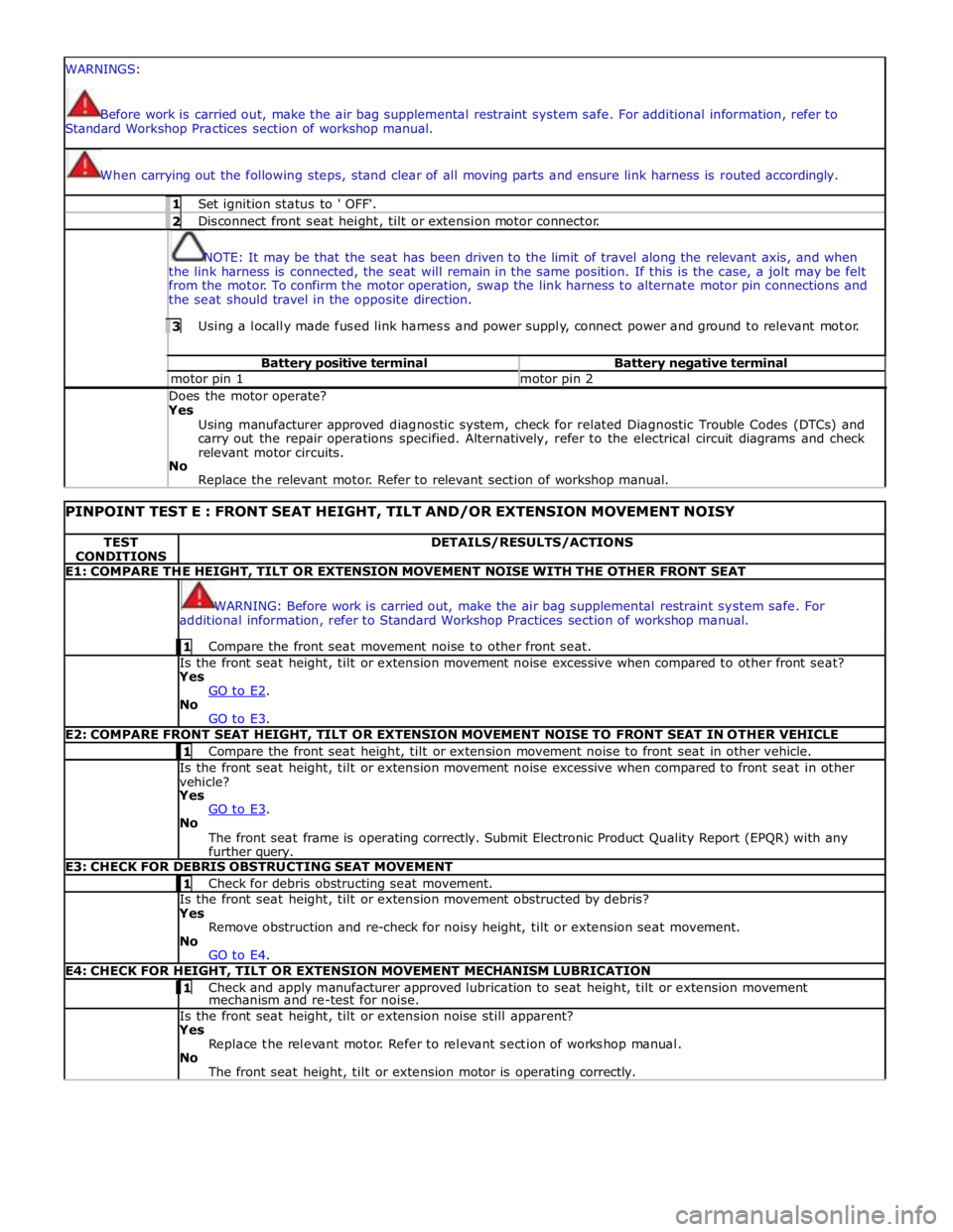
WARNINGS:
Before work is carried out, make the air bag supplemental restraint system safe. For additional information, refer to
Standard Workshop Practices section of workshop manual.
When carrying out the following steps, stand clear of all moving parts and ensure link harness is routed accordingly. 1 Set ignition status to ' OFF'. 2 Disconnect front seat height, tilt or extension motor connector.
NOTE: It may be that the seat has been driven to the limit of travel along the relevant axis, and when
the link harness is connected, the seat will remain in the same position. If this is the case, a jolt may be felt
from the motor. To confirm the motor operation, swap the link harness to alternate motor pin connections and
the seat should travel in the opposite direction. 3 Using a locally made fused link harness and power supply, connect power and ground to relevant motor. Battery positive terminal Battery negative terminal motor pin 1 motor pin 2 Does the motor operate? Yes
Using manufacturer approved diagnostic system, check for related Diagnostic Trouble Codes (DTCs) and
carry out the repair operations specified. Alternatively, refer to the electrical circuit diagrams and check
relevant motor circuits.
No
Replace the relevant motor. Refer to relevant section of workshop manual.
PINPOINT TEST E : FRONT SEAT HEIGHT, TILT AND/OR EXTENSION MOVEMENT NOISY TEST
CONDITIONS DETAILS/RESULTS/ACTIONS E1: COMPARE THE HEIGHT, TILT OR EXTENSION MOVEMENT NOISE WITH THE OTHER FRONT SEAT
WARNING: Before work is carried out, make the air bag supplemental restraint system safe. For
additional information, refer to Standard Workshop Practices section of workshop manual. 1 Compare the front seat movement noise to other front seat. Is the front seat height, tilt or extension movement noise excessive when compared to other front seat?
Yes
GO to E2. No
GO to E3. E2: COMPARE FRONT SEAT HEIGHT, TILT OR EXTENSION MOVEMENT NOISE TO FRONT SEAT IN OTHER VEHICLE 1 Compare the front seat height, tilt or extension movement noise to front seat in other vehicle. Is the front seat height, tilt or extension movement noise excessive when compared to front seat in other
vehicle?
Yes
GO to E3. No
The front seat frame is operating correctly. Submit Electronic Product Quality Report (EPQR) with any
further query. E3: CHECK FOR DEBRIS OBSTRUCTING SEAT MOVEMENT 1 Check for debris obstructing seat movement. Is the front seat height, tilt or extension movement obstructed by debris?
Yes
Remove obstruction and re-check for noisy height, tilt or extension seat movement.
No
GO to E4. E4: CHECK FOR HEIGHT, TILT OR EXTENSION MOVEMENT MECHANISM LUBRICATION 1 Check and apply manufacturer approved lubrication to seat height, tilt or extension movement mechanism and re-test for noise. Is the front seat height, tilt or extension noise still apparent?
Yes
Replace the relevant motor. Refer to relevant section of workshop manual.
No
The front seat height, tilt or extension motor is operating correctly.
Page 2341 of 3039
6. Locate climate seat module, (refer to Electrical Information - Electrical Reference Library, contained in TOPIx) for
guidance on how to gain access to the connector(s)
7. Locate and disconnect relevant connector prior to pin test
8. Using ohm-meter to probe each heat/cooled unit pins (at rear of connector), reading should achieve no greater than 10
ohms after 1 minute (initial fluctuations in readings may occur using ohm-meter, post 1 minute readings will have
stabilized)
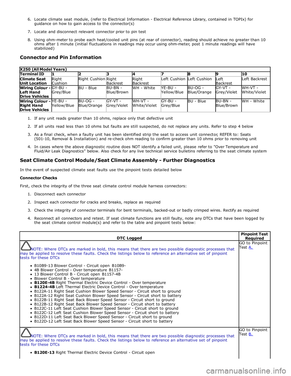
Connector and Pin Information
X250 (All Model Years) Terminal ID 1 2 3 4 7 8 9 10 Climate Seat
Unit Location Right
Cushion Right Cushion
Right
Backrest Right
Backrest Left Cushion Left Cushion
Left
Backrest Left Backrest Wiring Colour -
Left Hand
Drive Vehicles GY-BU -
Grey/Blue BU - Blue BU-BN -
Blue/Brown WH - White YE-BU - Yellow/Blue BU-OG -
Blue/Orange GY-VT -
Grey/Violet WH-VT -
White/Violet Wiring Colour -
Right Hand
Drive Vehicles YE-BU - Yellow/Blue BU-OG -
Blue/Orange GY-VT -
Grey/Violet WH-VT -
White/Violet GY-BU -
Grey/Blue BU - Blue BU-BN -
Blue/Brown WH - White
1. If any unit reads greater than 10 ohms, replace only that defective unit
2. If all units read less than 10 ohms but faults are still suspected, do not replace any units. Refer to step 4 below
3. As a final check, when a faulty unit has been identified strip the seat to access unit connector, REFER to: Seats
(501-10, Removal & Installation) and re-check ohm reading to confirm greater than 10 ohms prior to removing unit
4. In cases where the above diagnostic routine does NOT identify a failed unit, please refer to "Over Temperature and
Fluid/Air Leak Diagnostics" below. Also check for any live technical service bulletins referring to the seat climate system
Seat Climate Control Module/Seat Climate Assembly - Further Diagnostics
In the event of suspected climate seat faults use the pinpoint tests detailed below
Connector Checks
First, check the integrity of the three seat climate control module harness connectors:
1. Disconnect each connector
2. Inspect each connector for cracks and breaks, replace as required
3. Check the integrity of connector terminals for bent terminals, backed-out or badly crimped wires. Rectify as required
4. Reconnect all connectors and retest. If seat climate functions are still faulty, note any DTCs that have been logged by
the seat climate control module(s) and refer to the table and pinpoint tests below:
DTC Logged Pinpoint Test Required
NOTE: Where DTCs are marked in bold, this means that there are two possible diagnostic processes that
may be applied to resolve these faults. Check the listings below to reference an alternative set of pinpoint
tests for these DTCs
B10B9-13 Blower Control - Circuit open B10B9-
4B Blower Control - Over temperature B1157-
13 Blower Control B - Circuit open B1157-4B
Blower Control B - Over temperature
B120E-4B Right Thermal Electric Device Control - Over temperature
B1224-4B Left Thermal Electric Device Control - Over temperature
B122A-11 Right Seat Cushion Blower Speed Sensor - Circuit short to ground
B122A-12 Right Seat Cushion Blower Speed Sensor - Circuit short to battery
B122B-11 Right Seat Back Blower Speed Sensor - Circuit short to ground
B122B-12 Right Seat Back Blower Speed Sensor - Circuit short to battery
B122C-11 Left Seat Cushion Blower Speed Sensor - Circuit short to ground
B122C-12 Left Seat Cushion Blower Speed Sensor - Circuit short to battery
B122D-11 Left Seat Back Blower Speed Sensor - Circuit short to ground
B122D-12 Left Seat Back Blower Speed Sensor - Circuit short to battery GO to Pinpoint
Test A.
NOTE: Where DTCs are marked in bold, this means that there are two possible diagnostic processes that
may be applied to resolve these faults. Check the listings below to reference an alternative set of pinpoint
tests for these DTCs
B120E-13 Right Thermal Electric Device Control - Circuit open GO to Pinpoint
Test B.
Page 2418 of 3039
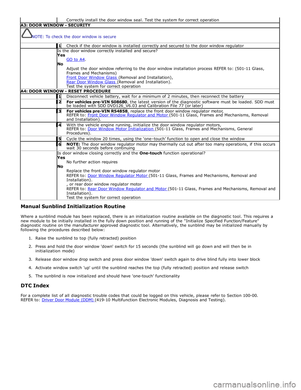
Correctly install the door window seal. Test the system for correct operation A3: DOOR WINDOW - SECURITY
NOTE: To check the door window is secure 1 Check if the door window is installed correctly and secured to the door window regulator Is the door window correctly installed and secure?
Yes
GO to A4. No
Adjust the door window referring to the door window installation process REFER to: (501-11 Glass,
Frames and Mechanisms)
Front Door Window Glass (Removal and Installation), Rear Door Window Glass (Removal and Installation). Test the system for correct operation A4: DOOR WINDOW - RESET PROCEDURE 1 Disconnect vehicle battery, wait for a minimum of 2 minutes, then reconnect the battery 2 For vehicles pre-VIN S08680, the latest version of the diagnostic software must be loaded. SDD must be loaded with SDD DVD126_V6.03 and Calibration File 77 (or later) 3 For vehicles pre-VIN R54858, replace the front door window regulator motor, REFER to: Front Door Window Regulator and Motor (501-11 Glass, Frames and Mechanisms, Removal and Installation). 4 With the vehicle engine running, initialize the door window regulator motors, REFER to: Door Window Motor Initialization (501-11 Glass, Frames and Mechanisms, General Procedures). 5 Cycle the window 20 times, using the ‘one–touch’ function to open and close the window 6 NOTE: The door window regulator motor may thermally cut out after too many operations, if this occurs wait 30 seconds before continuing Is door window closing correctly and the One-touch function operational?
Yes
No further action requires
No
Replace the front door window regulator motor
REFER to: Door Window Regulator Motor (501-11 Glass, Frames and Mechanisms, Removal and Installation).
, or rear door window regulator motor
REFER to: Rear Door Window Regulator and Motor (501-11 Glass, Frames and Mechanisms, Removal and Installation).
Test the system for correct operation Manual Sunblind Initialization Routine
Where a sunblind module has been replaced, there is an initialization routine available on the diagnostic tool. This requires a
new module to be initially installed in the fully down position and running of the "Initialize Specified Function/Feature"
diagnostic routine on the manufacturer approved diagnostic tool. Alternatively, the sunblind may be initialized manually by
following the procedures described below:
1. Raise the sunblind to top (fully retracted) position
2. Press and hold the door window 'down' switch for 15 seconds (the sunblind will go down and will then be in
initialization mode)
3. Release door window drop switch and press door window 'down' switch again to drive blind fully into lower block
4. Activate window switch 'up' until the sunblind reaches the top (fully retracted) position and release switch
5. The sunblind is now initialized and should have 'one-touch' functionality
DTC Index
For a complete list of all diagnostic trouble codes that could be logged on this vehicle, please refer to Section 100-00.
REFER to: Driver Door Module (DDM) (419-10 Multifunction Electronic Modules, Diagnosis and Testing).
Page 2469 of 3039
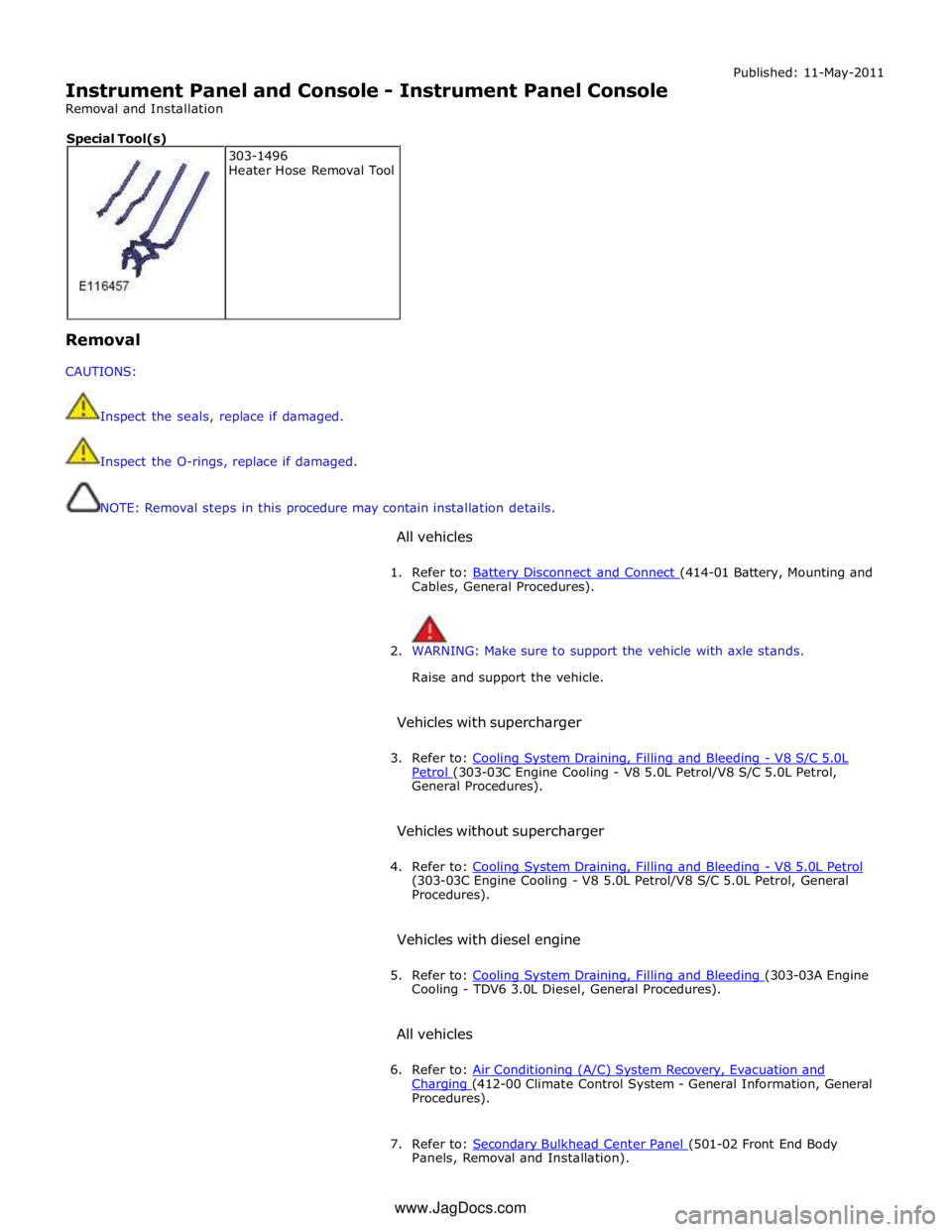
Instrument Panel and Console - Instrument Panel Console
Removal and Installation Published: 11-May-2011
Removal
CAUTIONS:
Inspect the seals, replace if damaged.
Inspect the O-rings, replace if damaged.
NOTE: Removal steps in this procedure may contain installation details.
All vehicles
1. Refer to: Battery Disconnect and Connect (414-01 Battery, Mounting and Cables, General Procedures).
2. WARNING: Make sure to support the vehicle with axle stands.
Raise and support the vehicle.
Vehicles with supercharger
3. Refer to: Cooling System Draining, Filling and Bleeding - V8 S/C 5.0L Petrol (303-03C Engine Cooling - V8 5.0L Petrol/V8 S/C 5.0L Petrol, General Procedures).
Vehicles without supercharger
4. Refer to: Cooling System Draining, Filling and Bleeding - V8 5.0L Petrol (303-03C Engine Cooling - V8 5.0L Petrol/V8 S/C 5.0L Petrol, General
Procedures).
Vehicles with diesel engine
5. Refer to: Cooling System Draining, Filling and Bleeding (303-03A Engine Cooling - TDV6 3.0L Diesel, General Procedures).
All vehicles
6. Refer to: Air Conditioning (A/C) System Recovery, Evacuation and Charging (412-00 Climate Control System - General Information, General Procedures).
7. Refer to: Secondary Bulkhead Center Panel (501-02 Front End Body Panels, Removal and Installation). 303-1496
Heater Hose Removal Tool Special Tool(s)
www.JagDocs.com
Page 2562 of 3039

Roof opening panel System Operation
Operation of the roof opening panel is controlled by the roof opening panel control module, which is integral with the motor.
The control module receives inputs from the CJB, which provides an 'open' or 'close' signal for remote handset operation, and
an 'enable' signal when the vehicle enters power mode 6.
The control module also receives a vehicle speed signal from the ABS module. The vehicle speed signal is used by the control
module to calibrate the anti-trap feature.
If the battery is disconnected, or the power supply is interrupted while the roof opening panel is in a partially open position,
the motor and control module will need to be calibrated to restore full functionality. To recalibrate:
1. Switch ignition on.
2. Press the front of the switch, so the roof opening panel is the tilt position, and then release the switch.
3. Press the front of the switch and hold for thirty seconds.
4. After thirty seconds the roof opening panel will begin to move. Keep the front of the switch pressed until the roof
opening panel has fully opened and then closed.
5. Once the open/close cycle has completed and the roof opening panel has stopped moving, release the switch.
6. The roof opening panel can now be operated as normal.
Drain hoses are connected to the front and rear corners of the roof opening panel frame. The drain hoses are located inside of
the cabin on the 'A' and 'D' post pillars to allow water, which has collected in the frame, to escape. One-way valves fitted to
the end of each drain hose, prevent the ingress of dirt and moisture.
Rear window sunblind
The powered rear window sunblind is operated through a switch in the roof console. Power to the sunblind motor is provided by
a pair of relays located in the CJB when the vehicle enters power mode 4. The sunblind motor is located beneath the rear parcel
shelf and is supplied as a sealed unit with the sunblind mechanism.
If the battery is disconnected or a replacement sunblind is fitted, the motor will require re-calibrating. To re-calibrate the
motor the sunblind should be powered through two-full cycles of movement.
Roof opening panel, motor Component Description
The roof opening panel motor has a worm drive which drives a gear in the cast housing attached to the end of the motor. The
gear has a small pinion gear attached to the outer part of its spindle. The pinion engages with two cables to form a rack and
pinion drive. Rotation of the motor turns the pinion which in turn drives the cables in the required direction.
The two cables are attached either side of the pinion. One end of each cable is attached to the guide; the opposite end of
each cable is held in position on the pinion by a metal insert in the frame. The cables run in channels, in the panel frame to
the guides. As the panel is closed the cables are pushed through channels in the front of the frame. The displaced cable is
guided into a further two channels in the frame, which protect the cable and prevent it from snagging. The cables
manufactured from rigid spring steel can pull as well as push the panel along the guides.
The motor contains a micro-switch and Hall effect sensor. Signals received from these components enable the control module
to calculate the exact position of the roof opening panel. The Hall effect sensor is also responsible for the operation of the
anti-trap function.
If the anti-trap feature is activated while the roof opening panel is closing, the panel is reversed for 200mm or as far as
possible. The Hall effect sensor, located in the motor, monitors the speed of the motor and if the speed decreases below a set
threshold, indicating an obstruction, the power feed to the motor is reversed so the panel goes back. In an emergency the
anti-trap function can be overridden by holding the switch in the closed position.
Roof opening panel, control module
The roof opening panel control module is integrated within the motor. The control module receives inputs from the CJB, which
provides an 'open' or 'close' signal for remote handset operation, and an 'enable' signal when the vehicle enters power mode 6.
The control module also contains the algorithm for the anti-trap system and receives a vehicle speed signal from the ABS
module. The vehicle speed signal is used by the control module to calibrate the anti-trap feature.
Page 2580 of 3039
Bumpers - Front Bumper
Removal and Installation Published: 11-May-2011
Removal
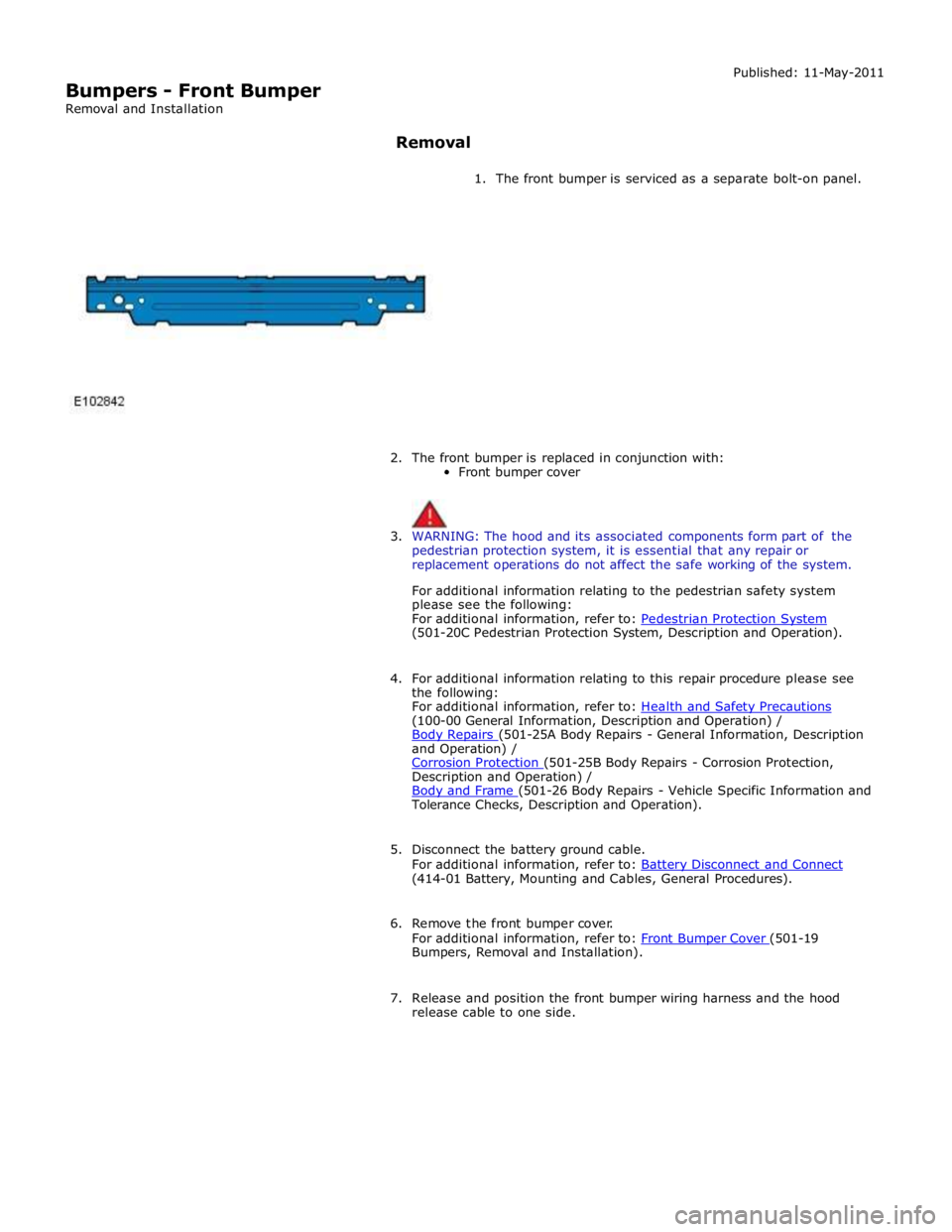
1. The front bumper is serviced as a separate bolt-on panel.
2. The front bumper is replaced in conjunction with:
Front bumper cover
3. WARNING: The hood and its associated components form part of the
pedestrian protection system, it is essential that any repair or
replacement operations do not affect the safe working of the system.
For additional information relating to the pedestrian safety system
please see the following:
For additional information, refer to: Pedestrian Protection System (501-20C Pedestrian Protection System, Description and Operation).
4. For additional information relating to this repair procedure please see
the following:
For additional information, refer to: Health and Safety Precautions (100-00 General Information, Description and Operation) /
Body Repairs (501-25A Body Repairs - General Information, Description and Operation) /
Corrosion Protection (501-25B Body Repairs - Corrosion Protection, Description and Operation) /
Body and Frame (501-26 Body Repairs - Vehicle Specific Information and Tolerance Checks, Description and Operation).
5. Disconnect the battery ground cable.
For additional information, refer to: Battery Disconnect and Connect (414-01 Battery, Mounting and Cables, General Procedures).
6. Remove the front bumper cover.
For additional information, refer to: Front Bumper Cover (501-19 Bumpers, Removal and Installation).
7. Release and position the front bumper wiring harness and the hood
release cable to one side.
Page 2616 of 3039
and the safety belt buckle sensor. Based on this data, the RCM decides which level of airbag module deployment is required and forwards the information to the second area, the deployment handler.
The deployment handler evaluates the status of the seat track position sensor and safety belt buckle sensors before a decision
is made about which restraints should finally be deployed.
Data from the side crash sensors is used by the RCM in conjunction with acceleration data from the RCM internal accelerometer to make a deployment decision. The RCM processes the acceleration data and subject to an impact being of high enough severity, decides whether the side airbag module should be deployed.
On board testing of the airbag modules, front safety belt pretensioner firing circuits, warning indicator circuits and module
status (the crash and side impact sensors perform basic self-tests) is performed by the RCM together with the storing of fault codes.
The RCM drives the SRS indicator on the instrument pack via a CAN signal. If the warning lamp fails, a fault code is recorded and a warning tone is sounded in place of the lamp if a further fault occurs. It also provides a temporary back-up power supply
to operate the airbag modules in the event that in crash conditions, the battery supply is lost. In the event of a crash, it
records certain data which can be accessed via the diagnostic connector.
A safing sensor in the RCM provides confirmation of an impact to verify if airbag and pretensioner activation is necessary. A roll-over sensor monitors the lateral attitude of the vehicle. Various firing strategies are employed by the RCM to ensure that during an accident only the appropriate airbags and pretensioners are fired. The firing strategy used also depends on the
inputs from the safety belt switches and the occupant monitoring system.
An energy reserve in the RCM ensures there is always a minimum of 150 milliseconds of stored energy available if the power supply from the ignition switch is disrupted during a crash. The stored energy is sufficient to produce firing signals for the
driver airbag, the passenger airbag and the safety belt pretensioners.
When the ignition is switched on, the RCM performs a self-test and then performs cyclical monitoring of the system. If a fault is detected the RCM stores a related fault code and illuminates the airbag warning indicator. The faults can be retrieved by the recommended Jaguar diagnostic tool over the CAN bus. If a fault that could cause a false fire signal is detected, the RCM disables the respective firing circuit, and keeps it disabled during a crash event.
Clock Spring
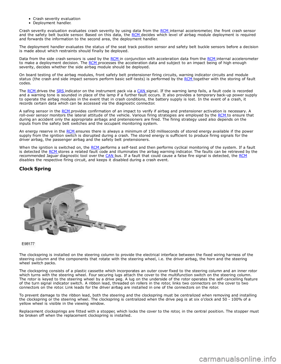
The clockspring is installed on the steering column to provide the electrical interface between the fixed wiring harness of the
steering column and the components that rotate with the steering wheel, i.e. the driver airbag, the horn and the steering
wheel switch packs.
The clockspring consists of a plastic cassette which incorporates an outer cover fixed to the steering column and an inner rotor
which turns with the steering wheel. Four securing lugs attach the cover to the multifunction switch on the steering column.
The rotor is keyed to the steering wheel by a drive peg. A lug on the underside of the rotor operates the self-cancelling feature
of the turn signal indicator switch. A ribbon lead, threaded on rollers in the rotor, links two connectors on the cover to two
connectors on the rotor. Link leads for the driver airbag are installed in one of the connectors on the rotor.
To prevent damage to the ribbon lead, both the steering and the clockspring must be centralized when removing and installing
the clockspring or the steering wheel. The clockspring is centralized when the drive peg is at six o'clock and 50 - 100% of a
yellow wheel is visible in the viewing window.
Replacement clocksprings are fitted with a stopper, which locks the cover to the rotor, in the central position. The stopper must
be broken off when the replacement clockspring is installed.
Page 2624 of 3039
Published: 10-Jul-2014
Supplemental Restraint System - Air Bag and Safety Belt Pretensioner
Supplemental Restraint System (SRS)
Diagnosis and Testing
Principle of Operation
For a detailed description of the supplemental restraints system and operation, refer to the relevant Description and Operation
section in the workshop manual. REFER to: (501-20B Supplemental Restraint System)
Air Bag and Safety Belt Pretensioner Supplemental Restraint System (SRS) (Description and Operation), Air Bag and Safety Belt Pretensioner Supplemental Restraint System (SRS) (Description and Operation), Air Bag and Safety Belt Pretensioner Supplemental Restraint System (SRS) (Description and Operation).
Inspection and Verification
WARNING: TO AVOID ACCIDENTAL DEPLOYMENT AND POSSIBLE PERSONAL INJURY, THE BACKUP POWER SUPPLY MUST
BE DEPLETED BEFORE REPAIRING OR REPLACING ANY AIR BAG SUPPLEMENTAL RESTRAINT SYSTEM (SRS) COMPONENTS. TO
DEPLETE THE BACKUP POWER SUPPLY ENERGY, DISCONNECT THE BATTERY GROUND CABLE AND WAIT ONE MINUTE. FAILURE
TO FOLLOW THIS INSTRUCTION MAY RESULT IN PERSONAL INJURY.
CAUTION: Diagnosis by substitution from a donor vehicle is NOT acceptable. Substitution of control modules does not
guarantee confirmation of a fault, and may also cause additional faults in the vehicle being tested and/or the donor vehicle.
NOTE: Given the legal implications of a restraints system failure, harness repairs to Air Bag module circuits are not
acceptable. Where the text refers to "REPAIR the circuit", this will normally mean the replacement of a harness.
1. Verify the customer concern.
2. Visually inspect for obvious signs of damage and system integrity.
3. If an obvious cause for an observed or reported concern is found, correct the cause (if possible) before proceeding to
the next step.
4. If the cause is not visually evident, check for Diagnostic Trouble Codes (DTCs) and refer to the DTC Index.
DTC Index
For a list of Diagnostic Trouble Codes (DTCs) that could be logged on this vehicle, please refer to Section 100-00.
REFER to: Diagnostic Trouble Code (DTC) Index - DTC: Restraints Control Module (RCM) (100-00 General Information, Description and Operation). Electrical
Battery condition, state of charge
Make sure all electrical connector(s) are engaged correctly on the air bag circuits
Wiring harness
Air bag module(s)
Make sure the restraints control module (RCM) is correctly installed
Fuse(s)
Sensor(s)
Pretensioner(s)
Warning lamp bulb(s) Visual Inspection
www.JagDocs.com