2010 JAGUAR XFR Replace Battery
[x] Cancel search: Replace BatteryPage 2012 of 3039
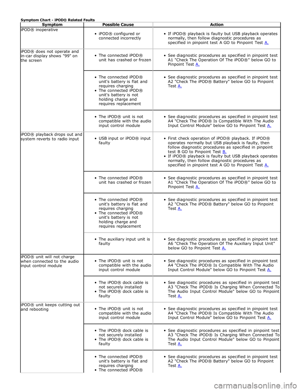
Symptom Chart - iPOD® Related Faults
Symptom Possible Cause Action iPOD® inoperative
iPOD® configured or
connected incorrectly
If iPOD® playback is faulty but USB playback operates
normally, then follow diagnostic procedures as
specified in pinpoint test A GO to Pinpoint Test A. iPOD® does not operate and
in-car display shows "99" on
the screen
The connected iPOD®
unit has crashed or frozen
See diagnostic procedures as specified in pinpoint test
A1 "Check The Operation Of The iPOD®" below GO to
Pinpoint Test A.
The connected iPOD®
unit's battery is flat and
requires charging
The connected iPOD®
unit's battery is not
holding charge and
requires replacement
See diagnostic procedures as specified in pinpoint test
A2 "Check The iPOD® Battery" below GO to Pinpoint
Test A.
The iPOD® unit is not
compatible with the audio
input control module
See diagnostic procedures as specified in pinpoint test
A4 "Check The iPOD® Is Compatible With The Audio
Input Control Module" below GO to Pinpoint Test A. iPOD® playback drops out and
system reverts to radio input
USB input or iPOD® input
faulty
First check operation of iPOD® playback. If iPOD®
operates normally but USB playback is faulty, then
follow diagnostic procedures as specified in pinpoint
test B GO to Pinpoint Test B. If iPOD® playback is faulty but USB playback operates
normally, then follow diagnostic procedures as
specified in pinpoint test A GO to Pinpoint Test A.
The connected iPOD®
unit has crashed or frozen
See diagnostic procedures as specified in pinpoint test
A1 "Check The Operation Of The iPOD®" below GO to
Pinpoint Test A.
The connected iPOD®
unit's battery is flat and
requires charging
The connected iPOD®
unit's battery is not
holding charge and
requires replacement
See diagnostic procedures as specified in pinpoint test
A2 "Check The iPOD® Battery" below GO to Pinpoint
Test A.
The auxiliary input unit is
faulty
See diagnostic procedures as specified in pinpoint test
A6 "Check The Operation Of The Auxiliary Input Unit"
below GO to Pinpoint Test A. iPOD® unit will not charge
when connected to the audio
input control module
The iPOD® unit is not
compatible with the audio
input control module
See diagnostic procedures as specified in pinpoint test
A4 "Check The iPOD® Is Compatible With The Audio
Input Control Module" below GO to Pinpoint Test A.
The iPOD® dock cable is
not securely installed
The iPOD® dock cable is
faulty
See diagnostic procedures as specified in pinpoint test
A3 "Check The iPOD® Is Charging When Connected To
The Audio Input Control Module" below GO to Pinpoint
Test A. iPOD® unit keeps cutting out
and rebooting
The iPOD® unit is not
compatible with the audio
input control module
See diagnostic procedures as specified in pinpoint test
A4 "Check The iPOD® Is Compatible With The Audio
Input Control Module" below GO to Pinpoint Test A.
The iPOD® dock cable is
not securely installed
The iPOD® dock cable is
faulty
See diagnostic procedures as specified in pinpoint test
A3 "Check The iPOD® Is Charging When Connected To
The Audio Input Control Module" below GO to Pinpoint
Test A.
The connected iPOD®
unit's battery is flat and
requires charging
The connected iPOD®
See diagnostic procedures as specified in pinpoint test
A2 "Check The iPOD® Battery" below GO to Pinpoint
Test A.
Page 2013 of 3039
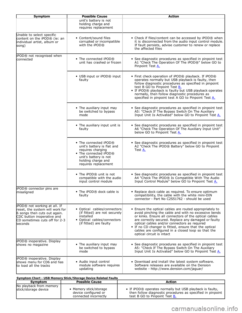
Symptom Possible Cause Action unit's battery is not
holding charge and
requires replacement Unable to select specific
content on the iPOD® (ie: an
individual artist, album or
song)
Content/sound files
corrupted or incompatible
with the iPOD®
Check if files/content can be accessed by iPOD® when
it is disconnected from the audio input control module.
If fault persists, advise customer to renew or replace
the affected files iPOD® not recognised when
connected
The connected iPOD®
unit has crashed or frozen
See diagnostic procedures as specified in pinpoint test
A1 "Check The Operation Of The iPOD®" below GO to
Pinpoint Test A.
USB input or iPOD® input
faulty
First check operation of iPOD® playback. If iPOD®
operates normally but USB playback is faulty, then
follow diagnostic procedures as specified in pinpoint
test B GO to Pinpoint Test B. If iPOD® playback is faulty but USB playback operates
normally, then follow diagnostic procedures as
specified in pinpoint test A GO to Pinpoint Test A.
The auxiliary input may
be switched to bypass
mode
See diagnostic procedures as specified in pinpoint test
A5: "Check If The Bypass Switch On The Auxiliary
Input Unit Is Activated" below GO to Pinpoint Test A.
The auxiliary input unit is
faulty
See diagnostic procedures as specified in pinpoint test
A6 "Check The Operation Of The Auxiliary Input Unit"
below GO to Pinpoint Test A.
The connected iPOD®
unit's battery is flat and
requires charging
The connected iPOD®
unit's battery is not
holding charge and
requires replacement
See diagnostic procedures as specified in pinpoint test
A2 "Check The iPOD® Battery" below GO to Pinpoint
Test A.
The iPOD® unit is not
compatible with the audio
input control module
See diagnostic procedures as specified in pinpoint test
A4 "Check The iPOD® Is Compatible With The Audio
Input Control Module" below GO to Pinpoint Test A. iPOD® connector pins are
misaligned
The iPOD® dock cable is
faulty
Replace dock cable as required. To ensure optimum
compatibility, the cable with the white mini-DIN
connector - Part No C2S51762 - should be used iPOD® not working at all. If
reset, the system will work for
6 songs then cuts out again.
CDC button inoperative and
CD sometimes cuts off for 2-3
seconds
Optical cables/connectors
(if fitted) are not securely
installed
Optical cables/connectors
(if fitted) are faulty
Ensure the optical cables are routed appropriately to
avoid pinching the cable and with no excessive bends
or kinks. Ensure all connectors of the optical cables
are correctly secured. Replace any damaged or faulty
optical cables and/or connectors as required
If no CD changer is fitted, ensure that the optical
cables are configured in a closed loop so that the
optical circuit is intact iPOD® inoperative. Display
shows no magazine
The auxiliary input may
be switched to bypass
mode
See diagnostic procedures as specified in pinpoint test
A5: "Check If The Bypass Switch On The Auxiliary
Input Unit Is Activated" below GO to Pinpoint Test A. iPOD® inoperative. Display
shows menu for CD6 and has
to load all the tracks
Audio input control
module software requires
updating
Download and install the latest system software.
Software releases are available on the Dension
website - http://www.dension.com/jaguar/ Symptom Chart - USB Memory Stick/Storage Device Related Faults
Symptom Possible Cause Action No playback from memory
stick/storage device
Memory stick/storage
device configured or
connected incorrectly
If iPOD® operates normally but USB playback is faulty,
then follow diagnostic procedures as specified in pinpoint
test B GO to Pinpoint Test B.
Page 2014 of 3039
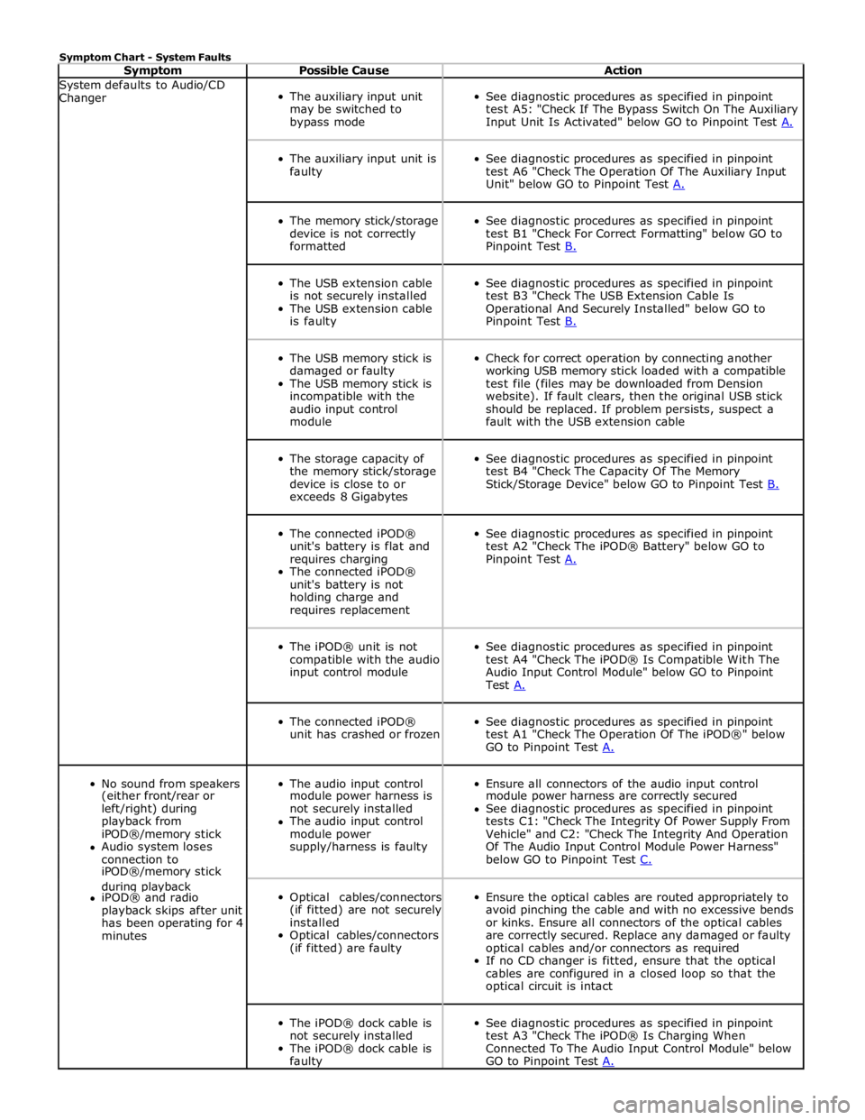
Symptom Chart - System Faults
Symptom Possible Cause Action System defaults to Audio/CD
Changer
The auxiliary input unit
may be switched to
bypass mode
See diagnostic procedures as specified in pinpoint
test A5: "Check If The Bypass Switch On The Auxiliary
Input Unit Is Activated" below GO to Pinpoint Test A.
The auxiliary input unit is
faulty
See diagnostic procedures as specified in pinpoint
test A6 "Check The Operation Of The Auxiliary Input
Unit" below GO to Pinpoint Test A.
The memory stick/storage
device is not correctly
formatted
See diagnostic procedures as specified in pinpoint
test B1 "Check For Correct Formatting" below GO to
Pinpoint Test B.
The USB extension cable
is not securely installed
The USB extension cable
is faulty
See diagnostic procedures as specified in pinpoint
test B3 "Check The USB Extension Cable Is
Operational And Securely Installed" below GO to
Pinpoint Test B.
The USB memory stick is
damaged or faulty
The USB memory stick is
incompatible with the
audio input control
module
Check for correct operation by connecting another
working USB memory stick loaded with a compatible
test file (files may be downloaded from Dension
website). If fault clears, then the original USB stick
should be replaced. If problem persists, suspect a
fault with the USB extension cable
The storage capacity of
the memory stick/storage
device is close to or
exceeds 8 Gigabytes
See diagnostic procedures as specified in pinpoint
test B4 "Check The Capacity Of The Memory
Stick/Storage Device" below GO to Pinpoint Test B.
The connected iPOD®
unit's battery is flat and
requires charging
The connected iPOD®
unit's battery is not
holding charge and
requires replacement
See diagnostic procedures as specified in pinpoint
test A2 "Check The iPOD® Battery" below GO to
Pinpoint Test A.
The iPOD® unit is not
compatible with the audio
input control module
See diagnostic procedures as specified in pinpoint
test A4 "Check The iPOD® Is Compatible With The
Audio Input Control Module" below GO to Pinpoint
Test A.
The connected iPOD®
unit has crashed or frozen
See diagnostic procedures as specified in pinpoint
test A1 "Check The Operation Of The iPOD®" below
GO to Pinpoint Test A.
No sound from speakers
The audio input control
Ensure all connectors of the audio input control (either front/rear or module power harness is module power harness are correctly secured left/right) during not securely installed See diagnostic procedures as specified in pinpoint playback from The audio input control tests C1: "Check The Integrity Of Power Supply From iPOD®/memory stick module power Vehicle" and C2: "Check The Integrity And Operation Audio system loses supply/harness is faulty Of The Audio Input Control Module Power Harness" connection to below GO to Pinpoint Test C. iPOD®/memory stick during playback
Optical cables/connectors
(if fitted) are not securely
installed
Optical cables/connectors
(if fitted) are faulty
Ensure the optical cables are routed appropriately to
avoid pinching the cable and with no excessive bends
or kinks. Ensure all connectors of the optical cables
are correctly secured. Replace any damaged or faulty
optical cables and/or connectors as required
If no CD changer is fitted, ensure that the optical
cables are configured in a closed loop so that the
optical circuit is intact iPOD® and radio playback skips after unit has been operating for 4 minutes
The iPOD® dock cable is
not securely installed
The iPOD® dock cable is
faulty
See diagnostic procedures as specified in pinpoint
test A3 "Check The iPOD® Is Charging When
Connected To The Audio Input Control Module" below
GO to Pinpoint Test A.
Page 2015 of 3039
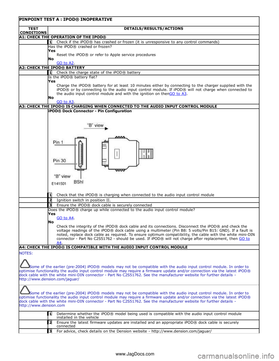
PINPOINT TEST A : IPOD® INOPERATIVE TEST
CONDITIONS DETAILS/RESULTS/ACTIONS A1: CHECK THE OPERATION OF THE IPOD® 1 Check if the iPOD® has crashed or frozen (it is unresponsive to any control commands) Has the iPOD® crashed or frozen?
Yes
Reset the iPOD® or refer to Apple service procedures
No
GO to A2. A2: CHECK THE IPOD® BATTERY 1 Check the charge state of the iPOD® battery Is the iPOD® battery flat?
Yes
Charge the iPOD® battery for at least 10 minutes either by connecting to the charger supplied with the
iPOD® or by connecting to the audio input control module. If iPOD® will not charge when connected to
the audio input control module and with the ignition on thenGO to A3. No
GO to A3. A3: CHECK THE IPOD® IS CHARGING WHEN CONNECTED TO THE AUDIO INPUT CONTROL MODULE iPOD® Dock Connector - Pin Configuration
1 Check that the iPOD® is charging when connected to the audio input control module 2 Ignition switch in position II. 3 Ensure the iPOD® dock cable is securely connected Does the iPOD® charge up while connected to the audio input control module?
Yes
GO to A4. No
Check the integrity of the iPOD® dock cable and its connections. Disconnect the iPOD® and check the
voltage readings of the iPOD® dock cable using a multimeter (Pin B8: 5 volts/Pin B15: GND). If a fault is
noted, replace dock cable as required. To ensure optimum compatibility, the cable with the white mini-DIN
connector - Part No C2S51762 - should be used. If iPOD® will not charge after replacement, then GO to A4. A4: CHECK THE IPOD® IS COMPATIBLE WITH THE AUDIO INPUT CONTROL MODULE NOTES:
Some of the earlier (pre-2004) iPOD® models may not be compatible with the audio input control module. In order to
optimise functionality the audio input control module may require a firmware update and/or connection via the latest iPOD®
dock cable with the white mini-DIN connector - Part No C2S51762. See the manufacturer website for further details -
http://www.dension.com/jaguar/
Some of the earlier (pre-2004) iPOD® models may not be compatible with the audio input control module. In order to
optimise functionality the audio input control module may require a firmware update and/or connection via the latest iPOD®
dock cable with the white mini-DIN connector - Part No C2S51762. See the manufacturer website for further details -
http://www.dension.com 1 Determine whether the iPOD® model being used is compatible with the audio input control module installed in the vehicle 2 Ensure the latest firmware updates are installed and an appropriate iPOD® dock cable is securely connected 3 For advice, check details on the Dension website - http://www.dension.com/jaguar/ www.JagDocs.com
Page 2017 of 3039
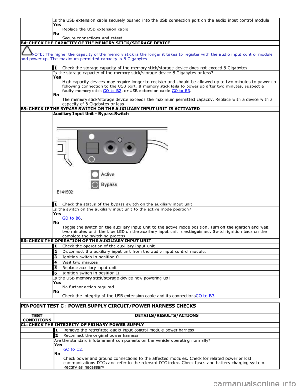
Is the USB extension cable securely pushed into the USB connection port on the audio input control module
Yes
Replace the USB extension cable
No
Secure connections and retest B4: CHECK THE CAPACITY OF THE MEMORY STICK/STORAGE DEVICE
NOTE: The higher the capacity of the memory stick is the longer it takes to register with the audio input control module
and power up. The maximum permitted capacity is 8 Gigabytes 1 Check the storage capacity of the memory stick/storage device does not exceed 8 Gigabytes Is the storage capacity of the memory stick/storage device 8 Gigabytes or less?
Yes
High capacity devices may require longer to register and should be allowed up to two minutes to power up
following connection to the USB port. If memory stick fails to power up after two minutes, suspect a
faulty memory stick GO to B2. or USB extension cable GO to B3. No
The memory stick/storage device exceeds the maximum permitted capacity. Replace with a device with a capacity of 8 Gigabytes or less B5: CHECK IF THE BYPASS SWITCH ON THE AUXILIARY INPUT UNIT IS ACTIVATED Auxiliary Input Unit - Bypass Switch
1 Check the status of the bypass switch on the auxiliary input unit Is the switch on the auxiliary input unit to the active mode position?
Yes
GO to B6. No
Toggle the switch on the auxiliary input unit to the active mode position. Turn off the ignition and wait
two minutes until the blue LED on the auxiliary input unit is extinguished. Switch ignition back on the complete the switching process B6: CHECK THE OPERATION OF THE AUXILIARY INPUT UNIT 1 Check the operation of the auxiliary input unit 2 Disconnect the auxiliary input unit from the audio input control module. 3 Ignition switch in position 0. 4 Wait two minutes 5 Replace auxiliary input unit 6 Ignition switch in position II. Is the USB memory stick/storage device now powering up?
Yes
No further action required
No
Check the integrity of the USB extension cable and its connectionsGO to B3.
PINPOINT TEST C : POWER SUPPLY CIRCUIT/POWER HARNESS CHECKS TEST
CONDITIONS DETAILS/RESULTS/ACTIONS C1: CHECK THE INTEGRITY OF PRIMARY POWER SUPPLY 1 Remove the retrofitted audio input control module power harness 2 Reconnect the original power harness Are the standard infotainment components on the vehicle operating normally?
Yes
GO to C2. No
Check power and ground connections to the affected modules. Check for related power or lost
communications DTCs and refer to the relevant DTC index. Check fuses and battery charging system. Rectify as necessary
Page 2143 of 3039
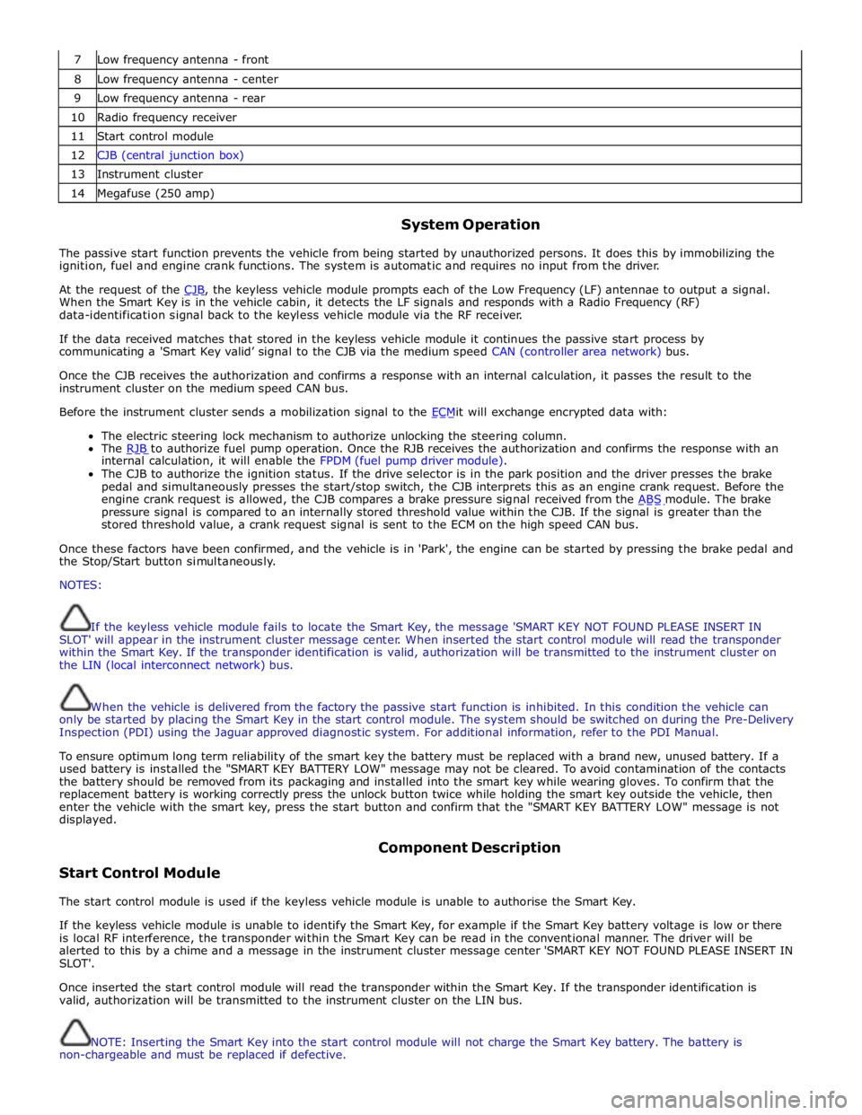
7 Low frequency antenna - front 8 Low frequency antenna - center 9 Low frequency antenna - rear 10 Radio frequency receiver 11 Start control module 12 CJB (central junction box) 13 Instrument cluster 14 Megafuse (250 amp)
System Operation
The passive start function prevents the vehicle from being started by unauthorized persons. It does this by immobilizing the
ignition, fuel and engine crank functions. The system is automatic and requires no input from the driver.
At the request of the CJB, the keyless vehicle module prompts each of the Low Frequency (LF) antennae to output a signal. When the Smart Key is in the vehicle cabin, it detects the LF signals and responds with a Radio Frequency (RF)
data-identification signal back to the keyless vehicle module via the RF receiver.
If the data received matches that stored in the keyless vehicle module it continues the passive start process by
communicating a 'Smart Key valid’ signal to the CJB via the medium speed CAN (controller area network) bus.
Once the CJB receives the authorization and confirms a response with an internal calculation, it passes the result to the
instrument cluster on the medium speed CAN bus.
Before the instrument cluster sends a mobilization signal to the ECMit will exchange encrypted data with: The electric steering lock mechanism to authorize unlocking the steering column.
The RJB to authorize fuel pump operation. Once the RJB receives the authorization and confirms the response with an internal calculation, it will enable the FPDM (fuel pump driver module).
The CJB to authorize the ignition status. If the drive selector is in the park position and the driver presses the brake
pedal and simultaneously presses the start/stop switch, the CJB interprets this as an engine crank request. Before the
engine crank request is allowed, the CJB compares a brake pressure signal received from the ABS module. The brake pressure signal is compared to an internally stored threshold value within the CJB. If the signal is greater than the
stored threshold value, a crank request signal is sent to the ECM on the high speed CAN bus.
Once these factors have been confirmed, and the vehicle is in 'Park', the engine can be started by pressing the brake pedal and
the Stop/Start button simultaneously.
NOTES:
If the keyless vehicle module fails to locate the Smart Key, the message 'SMART KEY NOT FOUND PLEASE INSERT IN
SLOT' will appear in the instrument cluster message center. When inserted the start control module will read the transponder
within the Smart Key. If the transponder identification is valid, authorization will be transmitted to the instrument cluster on
the LIN (local interconnect network) bus.
When the vehicle is delivered from the factory the passive start function is inhibited. In this condition the vehicle can
only be started by placing the Smart Key in the start control module. The system should be switched on during the Pre-Delivery
Inspection (PDI) using the Jaguar approved diagnostic system. For additional information, refer to the PDI Manual.
To ensure optimum long term reliability of the smart key the battery must be replaced with a brand new, unused battery. If a
used battery is installed the "SMART KEY BATTERY LOW" message may not be cleared. To avoid contamination of the contacts
the battery should be removed from its packaging and installed into the smart key while wearing gloves. To confirm that the
replacement battery is working correctly press the unlock button twice while holding the smart key outside the vehicle, then
enter the vehicle with the smart key, press the start button and confirm that the "SMART KEY BATTERY LOW" message is not
displayed.
Start Control Module Component Description
The start control module is used if the keyless vehicle module is unable to authorise the Smart Key.
If the keyless vehicle module is unable to identify the Smart Key, for example if the Smart Key battery voltage is low or there
is local RF interference, the transponder within the Smart Key can be read in the conventional manner. The driver will be
alerted to this by a chime and a message in the instrument cluster message center 'SMART KEY NOT FOUND PLEASE INSERT IN
SLOT'.
Once inserted the start control module will read the transponder within the Smart Key. If the transponder identification is
valid, authorization will be transmitted to the instrument cluster on the LIN bus.
NOTE: Inserting the Smart Key into the start control module will not charge the Smart Key battery. The battery is
non-chargeable and must be replaced if defective.
Page 2317 of 3039

memory positions to be stored and 'set' button with integral LED (light emitting diode). The seat, door mirror and steering
column motors have position sensors which provide feedback to driver's seat module.
Once the driver's seat, steering column and exterior mirrors have been adjusted, the vehicle is able to memorize these
settings for future use by using the following procedure:
Push the memory 'SET' button, the LED in the switch will illuminate Press the memory button 1 or 2 to memorize the current settings. The LED will extinguish, and a chime will sound to confirm that the settings have been memorized. If the ignition is on, power mode 6, the message center will display a
confirmation message.
The positions can be recalled by pressing the applicable button 1 or 2.
Stall Detection
Seat, steering column and mirror motors are deemed to have stalled if there is no change in the inputs that are received from
the corresponding feedback sensors for 200 ms (seat).
If a stall condition is detected then the drive to that motor is cancelled for the remainder of that memory operation (memory
recall) or until the switch is re-selected (manual movement).
If the motor movement has stopped due to loss of sensor feedback, either stall or sensor failure, then that motor may be
activated again, to move past the stall position, by re-selecting the appropriate switch and pressing for longer than 2 seconds.
This allows control of the motor to be maintained if sensor feedback is lost.
Upon re-selection of movement, if sensor pulses are detected then the motor will continue to be driven until the switch is
released or another stall condition is detected. If sensor feedback is not detected then the motor is only driven for 0.5 second
and then stops until the switch is released and then pressed again, when a further 0.5 second of activation is permitted, and
so on, this is known as inch mode.
For all seat motor manual movements, whenever a motor is driven and a stall occurs, the memory control module records the
position at which the stall occurred. If movement occurs beyond a stall position, then that position is erased from the control
modules memory. This will always allow movement past a previously recorded stall position once movement has been
registered beyond that position. This is the case for both manual and memory movement.
Initialization
When a replacement driver's seat module is fitted, it should be calibrated a Jaguar approved diagnostic system so that the
module can learn the seats absolute position.
Battery Monitor
If the battery voltage drops below 10.5 Volts, then the driver's seat module ignores all requests for a memory recall until the
battery voltage has reached 11.5 Volts. This will conserve as much power in the vehicle battery as possible to enable engine
cranking.
REAR SEATS - DESCRIPTION
The rear seat features a single piece cushion and a 60/40 split squab. Two latches are secured to the rear bulkhead by a pair
of M8 bolts to retain the seat squabs in the upright position. The latches can be released to fold down the individual cushions
by pulling a cable release located below the rear window parcel shelf in the luggage compartment.
ISOFIX fastening points are attached to the vehicle floor to provide secure fastening for compatible child seats.
A centrally mounted center arm rest can be folded down from the 60% squab. The arm rest contains two drinks holders.
Page 2334 of 3039
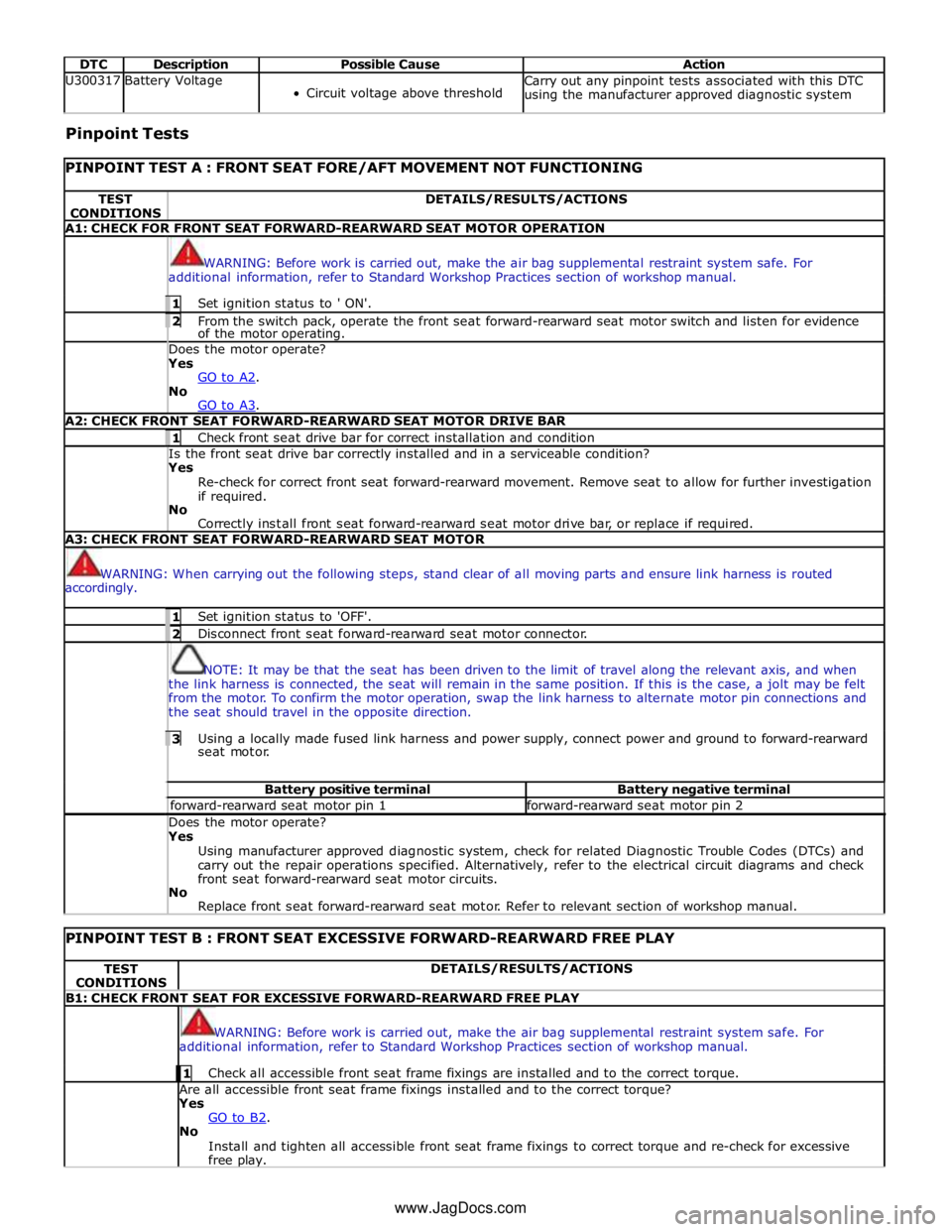
DTC Description Possible Cause Action U300317 Battery Voltage
Circuit voltage above threshold Carry out any pinpoint tests associated with this DTC
using the manufacturer approved diagnostic system Pinpoint Tests
PINPOINT TEST A : FRONT SEAT FORE/AFT MOVEMENT NOT FUNCTIONING TEST
CONDITIONS DETAILS/RESULTS/ACTIONS A1: CHECK FOR FRONT SEAT FORWARD-REARWARD SEAT MOTOR OPERATION
WARNING: Before work is carried out, make the air bag supplemental restraint system safe. For
additional information, refer to Standard Workshop Practices section of workshop manual. 1 Set ignition status to ' ON'. 2 From the switch pack, operate the front seat forward-rearward seat motor switch and listen for evidence of the motor operating. Does the motor operate? Yes
GO to A2. No
GO to A3. A2: CHECK FRONT SEAT FORWARD-REARWARD SEAT MOTOR DRIVE BAR 1 Check front seat drive bar for correct installation and condition Is the front seat drive bar correctly installed and in a serviceable condition? Yes
Re-check for correct front seat forward-rearward movement. Remove seat to allow for further investigation
if required.
No
Correctly install front seat forward-rearward seat motor drive bar, or replace if required. A3: CHECK FRONT SEAT FORWARD-REARWARD SEAT MOTOR
WARNING: When carrying out the following steps, stand clear of all moving parts and ensure link harness is routed
accordingly. 1 Set ignition status to 'OFF'. 2 Disconnect front seat forward-rearward seat motor connector.
NOTE: It may be that the seat has been driven to the limit of travel along the relevant axis, and when
the link harness is connected, the seat will remain in the same position. If this is the case, a jolt may be felt
from the motor. To confirm the motor operation, swap the link harness to alternate motor pin connections and
the seat should travel in the opposite direction. 3 Using a locally made fused link harness and power supply, connect power and ground to forward-rearward seat motor. Battery positive terminal Battery negative terminal forward-rearward seat motor pin 1 forward-rearward seat motor pin 2 Does the motor operate? Yes
Using manufacturer approved diagnostic system, check for related Diagnostic Trouble Codes (DTCs) and
carry out the repair operations specified. Alternatively, refer to the electrical circuit diagrams and check
front seat forward-rearward seat motor circuits.
No
Replace front seat forward-rearward seat motor. Refer to relevant section of workshop manual.
PINPOINT TEST B : FRONT SEAT EXCESSIVE FORWARD-REARWARD FREE PLAY TEST
CONDITIONS DETAILS/RESULTS/ACTIONS B1: CHECK FRONT SEAT FOR EXCESSIVE FORWARD-REARWARD FREE PLAY
WARNING: Before work is carried out, make the air bag supplemental restraint system safe. For
additional information, refer to Standard Workshop Practices section of workshop manual. 1 Check all accessible front seat frame fixings are installed and to the correct torque. Are all accessible front seat frame fixings installed and to the correct torque?
Yes
GO to B2. No
Install and tighten all accessible front seat frame fixings to correct torque and re-check for excessive
free play. www.JagDocs.com