2010 JAGUAR XFR Electrical
[x] Cancel search: ElectricalPage 2354 of 3039
Seating - Seat Smoothing
General Procedures Published: 01-May-2014
WARNINGS: Check
Make sure that the steamer is in the OFF position before connecting or disconnecting from the electrical outlet.
Do not use another high wattage device on the same electrical circuit.
If the use of an extension cord is absolutely necessary, the cord must be rated at a minimum of 10 amps.
To avoid the risk of electrical shock, check the condition of the power cord and the steamer before use.
Make sure that the steamer is disconnected from the electrical outlet before filling or emptying the water reservoir.
The steamer must only be used and placed on its stand on a stable surface.
To prevent injury such as burns, take care whilst using the steamer. Avoid coming into contact with the hot surface of the
steamer and do not direct steam toward any persons.
The steamer must ALWAYS be switched off when not in use or left unattended.
Do not allow the power cord to come into contact with the hot surface of the steamer.
CAUTIONS:
Protect the surrounding paintwork to avoid damage.
Protect the paintwork during this operation.
Do not use any additives in the steamer. Damage to the steamer or the seat cover can result if used.
NOTE: Some variation in the illustrations may occur, but the essential information is always correct.
1. CAUTIONS:
Steam the leather cushions evenly and progressively. Do not use
excessive force.
Take care not to damage the leather whilst steaming into the
corners.
Do not hold the steamer in one place for longer than 10 seconds,
as this will burn the leather and damage the covers. www.JagDocs.com
Page 2358 of 3039
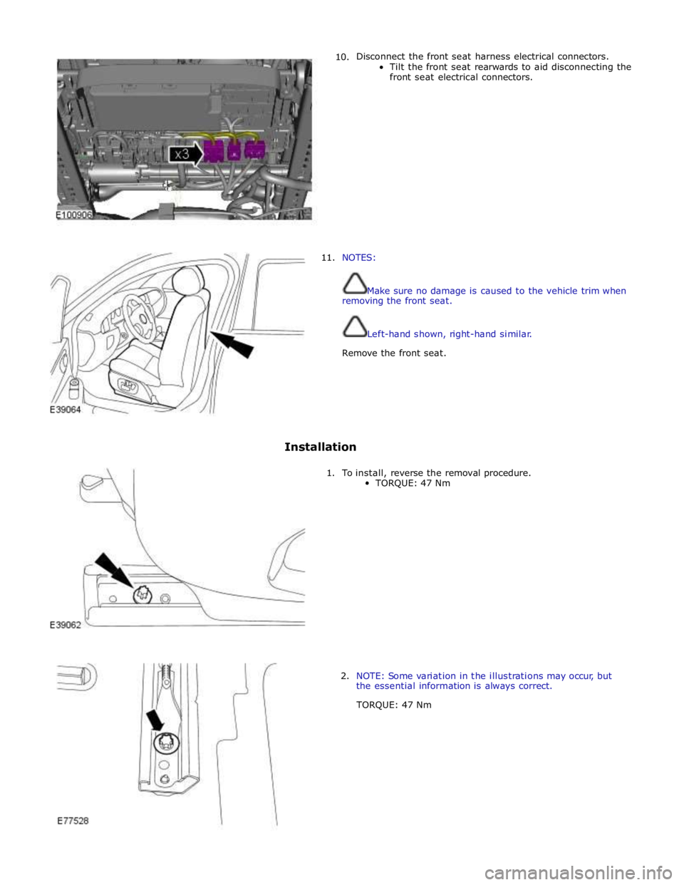
10. Disconnect the front seat harness electrical connectors.
Tilt the front seat rearwards to aid disconnecting the
front seat electrical connectors.
11. NOTES:
Make sure no damage is caused to the vehicle trim when
removing the front seat.
Left-hand shown, right-hand similar.
Remove the front seat.
Installation
1. To install, reverse the removal procedure.
TORQUE: 47 Nm
2. NOTE: Some variation in the illustrations may occur, but
the essential information is always correct.
TORQUE: 47 Nm
Page 2363 of 3039
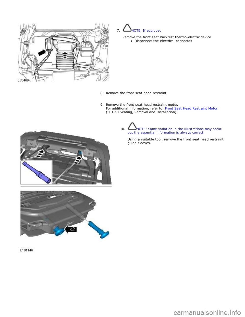
7. NOTE: If equipped.
Remove the front seat backrest thermo-electric device.
Disconnect the electrical connector.
8. Remove the front seat head restraint.
9. Remove the front seat head restraint motor.
For additional information, refer to: Front Seat Head Restraint Motor (501-10 Seating, Removal and Installation).
10. NOTE: Some variation in the illustrations may occur,
but the essential information is always correct.
Using a suitable tool, remove the front seat head restraint
guide sleeves.
Page 2376 of 3039
Seating - Seat Base
Removal and Installation
Removal
WARNINGS: Published: 11-May-2011
To avoid accidental deployment, the restraints control module backup power supply must be depleted. Wait at least one
minute after disconnecting the battery ground cable(s) before commencing any repair or adjustment to the supplemental
restraint system (SRS), or any component(s) adjacent to the SRS sensors. Failure to follow these instructions may result in
personal injury.
Always wear safety glasses when working on an air bag equipped vehicle and when handling an air bag module. Failure to
follow this instruction may result in personal injury.
To minimize the possibility of premature deployment, do not use radio key code savers when working on the
supplemental restraint system. Failure to follow this instruction may result in personal injury.
To minimize the possibility of injury in the event of premature deployment, always carry a live air bag module with the
bag and trim cover pointed away from the body. Failure to follow this instruction may result in personal injury.
To minimize the possibility of premature deployment, live air bag modules must only be placed on work benches which
have been ground bonded and with the trim cover facing up. Failure to follow these instructions may result in personal injury.
Never probe the electrical connectors of air bag modules or any other supplemental restraint system component. Failure
to follow this instruction may result in personal injury.
Painting over the driver air bag module trim cover or instrument panel could lead to deterioration of the trim cover and air
bags. Do not for any reason attempt to paint discolored or damaged air bag module trim covers or instrument panel. Install a
new component. Failure to follow this instruction may result in personal injury.
NOTES:
Some variation in the illustrations may occur, but the essential information is always correct.
Removal steps in this procedure may contain installation details.
1. Make the air bag supplemental restraint system (SRS) safe.
Refer to: Standard Workshop Practices (100-00 General Information, Description and Operation).
2. Refer to: Front Seat (501-10 Seating, Removal and Installation).
3. Refer to: Front Safety Belt Buckle (501-20A Safety Belt System, Removal and Installation).
4. Refer to: Front Seat Cushion Cover (501-10 Seating, Removal and Installation).
Page 2413 of 3039

Published: 11-May-2011
Glass, Frames and Mechanisms - Glass, Frames and Mechanisms - Overview
Description and Operation
Overview
The windshield is manufactured from laminated green-tinted glass with two variants of windshield being available: standard
and heated.
The rear window is manufactured from toughened green-tinted glass. The heated rear window grid-wire and antennas are
incorporated in the rear window. There are two variants of rear window dependant on the TV antenna specification.
The door windows are manufactured from green-tinted toughened glass. The driver and passenger windows are electrically
operated; the rear glass sections in the rear doors are fixed units. Door windows can be operated individually, or by the driver's
window control switch. An anti-trap function is included that stops the window's travel when an obstacle is detected in the in
the window's path.
Page 2416 of 3039

Rear Window
The rear window, manufactured from toughened 4mm green-tinted glass, is positioned to the vehicle's body by two locator
pins, one in each top corner of the windshield. This allows for the centralizing movement of the windshield across the car upon
fitment. The window is bonded and sealed to the vehicle body aperture using PU adhesive. The window finisher is a
three-sided extruded flip, taped onto the inner surface of the glass; this helps to centralize the glass in the aperture.
The heated rear window grid wire and antennas are incorporated in the rear window. There are two derivatives of rear window
dependant on the TV antenna specification.
Refer to: Video System (415-01, Description and Operation).
Door Windows
The door windows are manufactured from 4.85mm green-tinted toughened glass. The driver and passenger windows are
electrically operated, and are raised and lowered by a cable mechanism; the rear glass sections in the rear doors are fixed
units.
All windows can be operated individually, or by the driver's window control switch. The operation of the windows is proportional
to the switch activation. The driver window can be controlled by 'one touch' in an upward or downward direction. When the 'one
touch' operation is activated in the upwards direction an anti-trap sensor is automatically checked prior to the window closing.
If the anti-trap sensor is inoperative the window will not close. When the anti-trap sensor detects an obstacle in the window's
path, the upward travel of the window will automatically cease. Downward travel of the window will begin and then stop when a
preset time has elapsed.
Page 2417 of 3039
Published: 07-Mar-2014
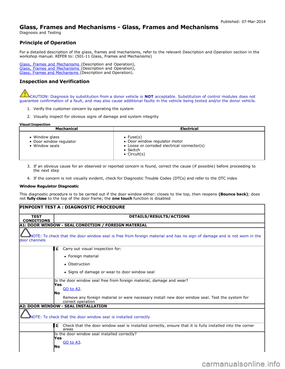
Glass, Frames and Mechanisms - Glass, Frames and Mechanisms
Diagnosis and Testing
Principle of Operation
For a detailed description of the glass, frames and mechanisms, refer to the relevant Description and Operation section in the
workshop manual. REFER to: (501-11 Glass, Frames and Mechanisms)
Glass, Frames and Mechanisms (Description and Operation), Glass, Frames and Mechanisms (Description and Operation), Glass, Frames and Mechanisms (Description and Operation).
Inspection and Verification
CAUTION: Diagnosis by substitution from a donor vehicle is NOT acceptable. Substitution of control modules does not
guarantee confirmation of a fault, and may also cause additional faults in the vehicle being tested and/or the donor vehicle.
1. Verify the customer concern by operating the system
2. Visually inspect for obvious signs of damage and system integrity
Visual Inspection
Mechanical Electrical
Window glass
Door window regulator
Window seals
Fuse(s)
Door window regulator motor
Loose or corroded electrical connector(s)
Switch
Circuit(s)
3. If an obvious cause for an observed or reported concern is found, correct the cause (if possible) before proceeding to
the next step
4. If the concern is not visually evident, check for Diagnostic Trouble Codes (DTCs) and refer to the DTC index
Window Regulator Diagnostic
This diagnostic procedure is to be carried out if the door window either: closes to the top, then reopens (Bounce back); does
not fully close to the top of the door frame; the one touch function is disabled
PINPOINT TEST A : DIAGNOSTIC PROCEDURE TEST
CONDITIONS DETAILS/RESULTS/ACTIONS A1: DOOR WINDOW - SEAL CONDITION / FOREIGN MATERIAL
NOTE: To check that the door window seal is free from foreign material and has no sign of damage and is not worn in the
door channels 1 Carry out visual inspection for: Foreign material
Obstruction
Signs of damage or wear to door window seal Is the door window seal free from foreign material, damage and wear?
Yes
GO to A2. No
Remove any foreign material or were necessary install new door window seal. Test the system for
correct operation A2: DOOR WINDOW - SEAL INSTALLATION
NOTE: To check that the door window seal is installed correctly 1 Check that the door window seal is installed correctly, ensure that it is fully installed into the corner areas Is the door window seal installed correctly?
Yes
GO to A3. No
Page 2419 of 3039
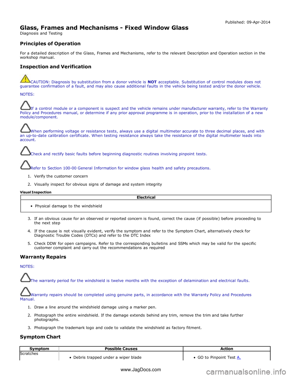
Glass, Frames and Mechanisms - Fixed Window Glass
Diagnosis and Testing
Principles of Operation Published: 09-Apr-2014
For a detailed description of the Glass, Frames and Mechanisms, refer to the relevant Description and Operation section in the
workshop manual.
Inspection and Verification
CAUTION: Diagnosis by substitution from a donor vehicle is NOT acceptable. Substitution of control modules does not
guarantee confirmation of a fault, and may also cause additional faults in the vehicle being tested and/or the donor vehicle.
NOTES:
If a control module or a component is suspect and the vehicle remains under manufacturer warranty, refer to the Warranty
Policy and Procedures manual, or determine if any prior approval programme is in operation, prior to the installation of a new
module/component.
When performing voltage or resistance tests, always use a digital multimeter accurate to three decimal places, and with
an up-to-date calibration certificate. When testing resistance always take the resistance of the digital multimeter leads into
account.
Check and rectify basic faults before beginning diagnostic routines involving pinpoint tests.
Refer to Section 100-00 General Information for window glass health and safety precautions.
1. Verify the customer concern
2. Visually inspect for obvious signs of damage and system integrity
Visual Inspection
3. If an obvious cause for an observed or reported concern is found, correct the cause (if possible) before proceeding to
the next step
4. If the cause is not visually evident, verify the symptom and refer to the Symptom Chart, alternatively check for
Diagnostic Trouble Codes (DTCs) and refer to the DTC Index
5. Check DDW for open campaigns. Refer to the corresponding bulletins and SSMs which may be valid for the specific
customer complaint and carry out the recommendations as required
Warranty Repairs
NOTES:
The warranty period for the windshield is twelve months with the exception of delamination and electrical faults.
Warranty repairs should be completed using genuine parts, in accordance with the Warranty Policy and Procedures
Manual.
1. Draw a line around the windshield damage using a marker pen.
2. Photograph the entire windshield. If the damage extends behind any trim, remove the trim and take further
photographs.
3. Photograph the trademark logo and code to validate the windshield as factory fitment.
Symptom Chart
Symptom Possible Causes Action Scratches
Debris trapped under a wiper blade
GO to Pinpoint Test A. Electrical
Physical damage to the windshield
www.JagDocs.com