2010 JAGUAR XFR ECO mode
[x] Cancel search: ECO modePage 1643 of 3039
Automatic braking is limited to approximately 30% of full pressure (0.3G deceleration) and is intended to provide a
smooth, gradual deceleration in follow mode conditions. Harsh braking by the target vehicle or following the target
vehicle down to very low speeds or to a halt will require driver override of the brakes.
While the radar sensor detects moving and stationary targets for assessment of the environment ahead, the system
does not react to or provide any control in situations other than follow mode conditions. Stationary or slow moving
vehicles (below 10 km/h), pedestrians, objects on the road and oncoming vehicles in the same lane are not recognized.
WARNING: The adaptive speed control system is not a collision warning or avoidance system and that, other than the
limited conditions of follow mode, driver intervention will be necessary to control the vehicle speed.
In follow mode, some situations may cause target ambiguities for the detection system. These situations include:
The nearby presence of a third vehicle when driving on a line slightly offset to the target vehicle.
Vehicles edging into the lane ahead which are not detected by the system until they have moved into the radar beam.
On the approach to, or exit from a bend, a target vehicle may be lost or a new target acquired as vehicles ahead change their
angular position with respect to the radar sensor. On a straight road, if the sensing vehicle is in follow mode below its selected
set speed, losing the target vehicle will cause the sensing vehicle to accelerate to this set speed. This acceleration is
undesirable either on, or entering a bend when the target is suddenly lost, and in this situation the system inhibits the
resumption of the set speed.
The speed control system compares vehicle speed data from the ABS system with the relative speed of an external object as
detected by the radar sensor to ascertain whether the object is stationary or not.
NOTE: If tires are fitted which are different in diameter from those specified for the vehicle, the vehicle speed calculated
by the ABS will not be the true road speed. This situation may cause stationary objects to be falsely identified as moving
vehicles and result in automatic deceleration on a clear road.
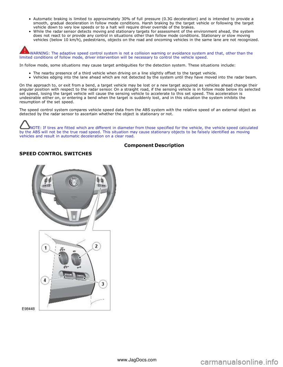
SPEED CONTROL SWITCHES Component Description
www.JagDocs.com
Page 1710 of 3039
control switch on the integrated control panel or the + and - soft buttons on the touch screen display (TSD). The ATC module also adjusts blower speed to compensate for the ram effect on inlet air produced by forward movement of the vehicle. As
vehicle speed and ram effect increases, blower motor speed is reduced, and vice versa.
Air Distribution Control
Two air distribution doors are used to direct air into the passenger compartment. The doors are operated by stepper motors,
which are controlled by the ATC module using LIN bus messages.
When the A/C system is in automatic mode, the ATC module automatically controls air distribution into the passenger compartment in line with its 'comfort' algorithm. Automatic control is overridden if any of the TSD air distribution soft buttons
are selected. Air distribution in the passenger compartment will remain as selected until the 'Auto' switch is pressed or a
different manual selection is made.
A/C Compressor Control
When A/C is selected the ATC module maintains the evaporator at an operating temperature that varies with the passenger compartment cooling requirements. If the requirement for cooled air decreases, the ATC module raises the evaporator operating temperature by reducing the flow of refrigerant provided by the A/C compressor. The ATC module closely controls the rate of temperature increase to avoid introducing moisture into the passenger compartment.
If the requirement for cooled air increases, the ATC module lowers the evaporator operating temperature by increasing the flow of refrigerant provided by the A/C compressor.
When A/C is off, the compressor current signal supplied by the ATC module holds the A/C compressor solenoid valve in the minimum flow position, effectively switching off the A/C function.
The ATC module incorporates limits for the operating pressure of the refrigerant system. If the system approaches the high pressure limit, the compressor current signal is progressively reduced until the system pressure decreases. If the system falls
below the low pressure limit, the compressor current signal is held at its lowest setting so that the A/C compressor is maintained at its minimum stroke. This avoids depletion of the lubricant from the A/C compressor.
A/C Compressor Torque
The ATC module transmits refrigerant pressure and A/C compressor current values to the ECM (engine control module) over the medium speed then high speed CAN bus, using the CJB as a gateway. The ECM uses these values to calculate the torque being used to drive the A/C compressor. The ECM compares the calculated value with its allowable value and if necessary forces the ATC module to inhibit the A/C compressor by transmitting the 'ACClutchInhibit' CAN message. This forces the ATC module to reduce the drive current to the A/C compressor solenoid valve, which reduces refrigerant flow. This in turn reduces the torque required to drive the A/C compressor.
By reducing the maximum A/C compressor torque, the ECM is able to reduce the load on the engine when it needs to maintain vehicle performance or cooling system integrity.
Cooling Fan Control
The ATC module determines the amount of condenser cooling required from the refrigerant pressure sensor, since there is a direct relationship between the temperature and pressure of the refrigerant. The cooling requirement is broadcast to the ECM on the medium speed CAN bus. The ECM then controls the temperature of the condenser using the cooling fan.
Programmed Defrost
The programmed defrost DEF switch is located on the integrated control panel. When the switch is pressed, the ATC module instigates the programmed defrost function. When selected, the ATC module configures the system as follows:
Automatic mode off.
A/C on. Selected temperature unchanged.
Air inlet set to fresh air.
Air distribution set to windshield.
Blower speed set to level 6.
Windshield heater (where fitted) and rear window heater on.
The programmed defrost function can be cancelled by one of the following:
Selecting any air distribution switch on the TSD.
Pressing the AUTO switch on the integrated control panel.
A second press of the DEF button.
Switching the ignition OFF.
The blower speed can be adjusted without terminating the programmed defrost function.
Rear Window Heater
Rear window heater operation is only enabled when the engine is running. The ATC module controls operation of the rear window heater using a relay in the RJB. When rear window heater operation is required, the ATC module broadcasts a message to the RJB on the medium speed CAN bus. On receipt of the message, the RJB energizes the relay by providing a ground path for the relay coil. This allows a battery feed to flow across the relay to power the rear window heater element.
Page 1711 of 3039
rear window heater switch is pressed or the engine stops.
Automatic operation during a journey is initiated when low ambient air temperatures are experienced and the vehicle has been
travelling for a set period of time above a threshold speed. In this instance, no feedback is given to the driver to inform him
the rear window heater is operational (the switch LED is not illuminated). The duration of heater operation is variable depending on the ambient air temperature, vehicle speed and the amount of time the vehicle has been travelling.
Windshield Heater (Where Fitted)
Windshield heater operation is only enabled when the engine is running. The ATC module controls operation of the windshield heater using two relays in the EJB (engine junction box). When windshield heater operation is required, the ATC module broadcasts a message to the CJB on the medium speed CAN bus. On receipt of the message, the CJB energizes the relays by providing a ground path for both relay coils. This allows a battery feed to flow across the relays to power the windshield left
and right heater elements.
There are two modes of windshield heater operation; manual and automatic.
Manual operation is activated by pressing the windshield heater switch on the integrated control panel. When the switch is
pressed, the status LED in the switch illuminates and the windshield heater elements are energized. Manual operation is discontinued when the windshield heater switch is pressed a second time, 5 minutes have elapsed (the heating phase), or the
engine stops. If manual operation is discontinued by the engine stopping, the previous heating phase is resumed if the engine
is re-started within 30 seconds.
There are two variants of automatic operation; automatic operation at the start of a journey and automatic operation during a
journey.
Automatic operation at the start of a journey is initiated if the ambient air temperature is below 5 °C (41 °F). In this instance,
the switch LED is illuminated and the heater elements are energized for 6.5 minutes. Automatic operation is discontinued if the windshield heater switch is pressed or the engine stops.
Automatic operation during a journey is initiated when low ambient air temperatures are experienced and the vehicle has been
travelling for a set period of time above a threshold speed. In this instance, no feedback is given to the driver to inform him
the windshield heater is operational (the switch LED is not illuminated) and the duration of operation is variable depending upon the ambient air temperature, vehicle speed and the amount of time the vehicle has been travelling.
Exterior Mirror Heaters
Operation of the exterior mirror heaters is fully automatic and not controllable by the driver. Exterior mirror heater operation is
determined by ambient air temperature and windshield wiper status. When ambient air temperature reaches a pre-determined
level, the ATC module broadcasts an exterior mirror heating request to the door modules over the medium speed CAN bus. On receipt of this message, the door modules provide feed and ground connections to both exterior mirror heater elements.
The amount of time the exterior mirror heaters are operational increases if the windshield wipers are switched on. This ensures
the mirrors remain mist free in damp and wet conditions, where there is an increased risk of misting.
Seat Heaters (Where Fitted)
There are four seat heater settings available; off, 1, 2 and 3, which can be selected on the home and climate control screens
of the TSD. The heat setting is relayed to the vehicle occupants through a graduated display on the TSD.
Operation of the heated seats is controlled by the ATC module. When the ATC module receives a heating request from the TSD, it broadcasts a message to the CJB over the medium speed CAN bus. The CJB then provides a hardwired 12 V supply to the three heater elements in the related front seat. The heater elements, two in the seat cushion and one in the seat squab,
are wired in series. The ATC module monitors seat temperature using a temperature sensor located in each seat cushion. The CJB provides the temperature sensors with a 5 V supply. The level of the returned voltage back to the CJB is proportional to the seat temperature. The value of the return signal is broadcast to the ATC module, over the medium speed CAN bus, which allows it to control the seat temperature to the required level. The ATC module will suspend or disable operation of the seat heaters if any of the following occur:
Battery voltage exceeds 16.5 ± 0.3 V for more than 5 seconds. Seat heating is re-enabled when battery voltage
decreases to 16.2 ± 0.3 V.
If a short or open circuit is detected.
If the seat heat temperature rises significantly above the target temperature setting.
The graduated display on the TSD remains illuminated until the seat heaters are turned off or the engine stops. If the engine
is restarted within 30 seconds the seat heater resumes the previous heating level.
Page 1722 of 3039
Climate Control - Center Registers
Removal and Installation
Removal Published: 11-May-2011
CAUTION: Do not manually open the registers. Failure to follow this instruction may result in damage to the internal
components.
NOTES:
The center registers must be open before carrying out this procedure. To achieve this set the registers to 'Always Open'
using the climate settings tab on the information and entertainment display. If the registers are set to 'Automatic' mode
(rotating with ignition on/off) and one or more are disconnected during an ignition cycle, a vehicle battery reset may be
required to reconnect the affected registers to the LIN BUS.
Removal steps in this procedure may contain installation details.
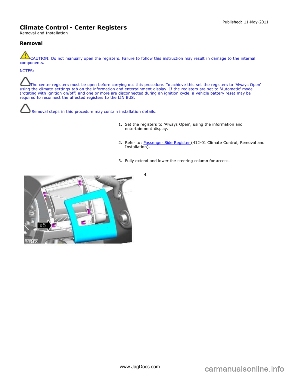
1. Set the registers to 'Always Open', using the information and
entertainment display.
2. Refer to: Passenger Side Register (412-01 Climate Control, Removal and Installation).
3. Fully extend and lower the steering column for access.
4. www.JagDocs.com
Page 1729 of 3039
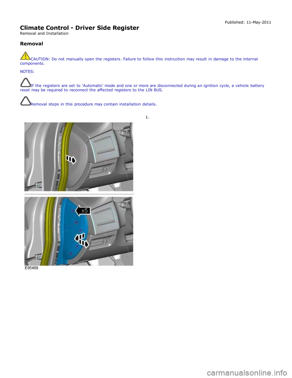
Climate Control - Driver Side Register
Removal and Installation
Removal Published: 11-May-2011
CAUTION: Do not manually open the registers. Failure to follow this instruction may result in damage to the internal
components.
NOTES:
If the registers are set to 'Automatic' mode and one or more are disconnected during an ignition cycle, a vehicle battery
reset may be required to reconnect the affected registers to the LIN BUS.
Removal steps in this procedure may contain installation details.
1.
Page 1736 of 3039
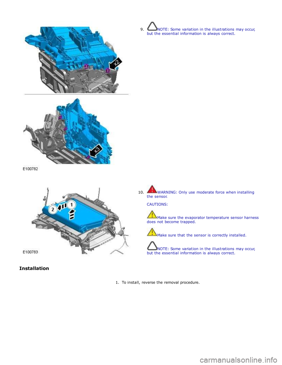
Installation
9.
10.
NOTE: Some variation in the illustrations may occur,
but the essential information is always correct.
WARNING: Only use moderate force when installing
the sensor.
CAUTIONS:
Make sure the evaporator temperature sensor harness
does not become trapped.
Make sure that the sensor is correctly installed.
NOTE: Some variation in the illustrations may occur,
but the essential information is always correct.
1. To install, reverse the removal procedure.
Page 1751 of 3039
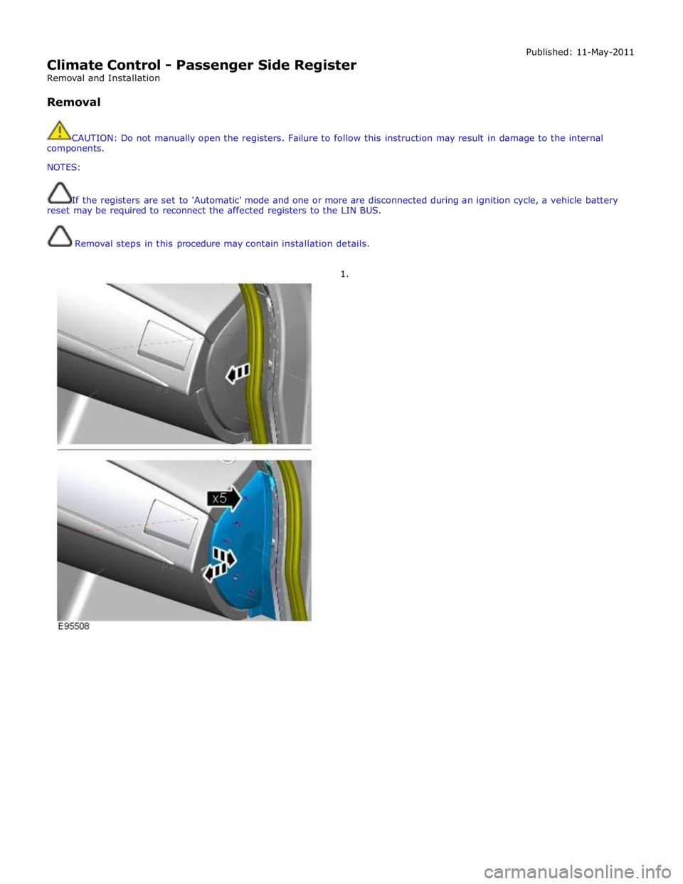
Climate Control - Passenger Side Register
Removal and Installation
Removal Published: 11-May-2011
CAUTION: Do not manually open the registers. Failure to follow this instruction may result in damage to the internal
components.
NOTES:
If the registers are set to 'Automatic' mode and one or more are disconnected during an ignition cycle, a vehicle battery
reset may be required to reconnect the affected registers to the LIN BUS.
Removal steps in this procedure may contain installation details.
1.
Page 1786 of 3039
6. Adaptive Speed Control Indicator
The adaptive speed control system is controlled by the adaptive speed control module. Operation of the SET +/- switches on
the steering wheel will activate the system. Operation of the switches is detected by the adaptive speed control module. The
module issues a high speed CAN message to the instrument cluster which illuminates the adaptive speed control indicator, when the system is in 'follow mode', in an amber color and displays a 'SETSPEED XXX MPH / KM/H' message in the message
center. The indicator is illuminated in an amber color for a 3 second indicator check when the ignition is switched on.
7. Anti-lock Braking System (ABS) Warning Indicator
The ABS warning indicator is controlled by the ABS module. If a fault in the ABS system is detected by the ABS module, the module issues a high speed CAN message to the instrument cluster to illuminate the ABS warning indicator in an amber color and display the message 'ABS FAULT' in the instrument cluster. The indicator is illuminated in an amber color for a 3 second
indicator check when the ignition is switched on. If a fault is present when the ignition is on, the bulb will remain illuminated
after the 3 second indicator check period.
NOTES:
The 'ABS FAULT' message is not displayed in NAS markets).
If both the ABS warning indicator and the brake warning indicator illuminate simultaneously, a major fault in the brake system will have occurred.
On NAS vehicles, the ABS warning indicator is also used for parking brake operation. The NAS warning indicator does not have 'ABS' on the icon and will function as described previously for the parking brake operation of the brake warning indicator.
8. Engine Malfunction Indicator Lamp (MIL)
The MIL warning indicator is controlled by the ECM and illuminated by the instrument cluster on receipt of a message on the high speed CAN bus from the ECM. The indicator is illuminated in an amber color for a 3 second indicator check when the ignition is switched on.
If the MIL remains illuminated after the engine is started or illuminates when driving, a fault is present and must be
investigated at the earliest opportunity. Illumination of the MIL warning indicator alerts the driver to an OBD (on-board
diagnostic) fault which will cause excessive emissions output. This may relate to either an engine management system fault or
a transmission.
9. Tire Pressure Monitoring System (TPMS) Warning Indicator
The TPMS warning indicator is illuminated by the instrument cluster on receipt of a medium speed CAN message from the TPMS module. The indicator is illuminated in an amber color for a 3 second indicator check when the ignition is switched on.
If the indicator illuminates and is accompanied by the message 'TYRE PRESSURE SYSTEM FAULT' in the message center, then a
TPMS fault has occurred. If the indicator illuminates and accompanied by a different message, then a low tire pressure has
been detected, a spare wheel has been fitted or a TPMS sensor has failed.
10. Airbag Warning Indicator
The airbag warning indicator is controlled by the instrument cluster. The indicator is illuminated in an amber color for the 3
second indicator check when the ignition is switched on. The indicator remains illuminated after the 3 second period has
expired until the instrument cluster receives a turn off message on the high speed CAN bus from the RCM (restraints control module).
11. Front Fog Lamp Indicator
The green colored front fog lamp indicator is controlled by the CJB and illuminated by the instrument cluster on receipt of a front fog lamp on message on the medium speed CAN bus from the CJB. The indicator is illuminated for as long as the front fog lamps are active. The front fog lamp indicator is not subject to the 3 second indicator check when the ignition is switched
on.
12. Dynamic Stability Control (DSC) Indicator
The DSC warning lamp is controlled by the ABS module and illuminated by the instrument cluster in response to messages received on the high speed CAN bus. The indicator is illuminated in an amber color for the 3 second indicator check when the ignition is switched on. The DSC warning indicator, are permanently illuminated in an amber color if the instrument cluster
receives a high speed CAN message from the ABS module relating to one of the following faults:
Traction control fault
Yaw control fault
Engine drag torque control fault
Panic Brake Assist (PBA) fault
Signal missing relating to either traction control active, yaw control active or DSC switch input.
The above faults will also generate an applicable DSC and ABS warning message in the message center. The DSC warning
indicator will flash at 2 Hz for if the traction control or yaw control is active when the DSC system is enabled. If the DSC
system is switched off, the warning indicator will be permanently illuminated until the DSC system is subsequently
re-activated.
13. Safety Belt Warning Indicator
The safety belt warning indicator operates for both the driver and passenger safety belts. The warning indicator is controlled by