2010 JAGUAR XFR ECO mode
[x] Cancel search: ECO modePage 1979 of 3039
VICS (vehicle information and communication system) receiver (Japan only)
TMC (traffic message channel) receiver (Europe only)
JaguarVoice control module
The navigation computer contains a solid state piezo gyro which measures the motion of the vehicle around its vertical axis.
The gyro operates on the principle known as the coriolis force. The coriolis force is the force that appears to accelerate a body
moving away from its rotational axis against the direction of rotation of the axis.
Using inputs from the ABS module, the GPS antenna and the gyro sensor, the computer calculates the vehicle's current position, direction and speed.
The navigation computer houses the DVD (digital versatile disc) drive. The drive is used to read map data from region specific
DVD's. The number of DVD's issued per region varies depending on the amount of information available. The regions are as follows:
Europe (2 versions, Western Europe and Whole of Europe)
NAS (North American specification)
Japan, Middle East, Australia and South Africa
A button, located adjacent to the DVD slot, is provided to eject the DVD from the unit. Prior to ejecting the disc the slot protection has to be slid to the side. If the ignition is on, or the entertainment system is in 1-hour mode, one press of the
button will eject the DVD.
The navigation computer uses non-volatile memory to store settings and configuration information when it is powered down.
This process takes place just before the computer turns off.
No configuration procedure is required if the navigation computer is replaced. There is no option to calibrate the navigation
computer using the Jaguar approved diagnostic equipment; however in some regions a software download, contained in the
DVD disc, is required before the navigation system becomes operational.
MICROPHONE
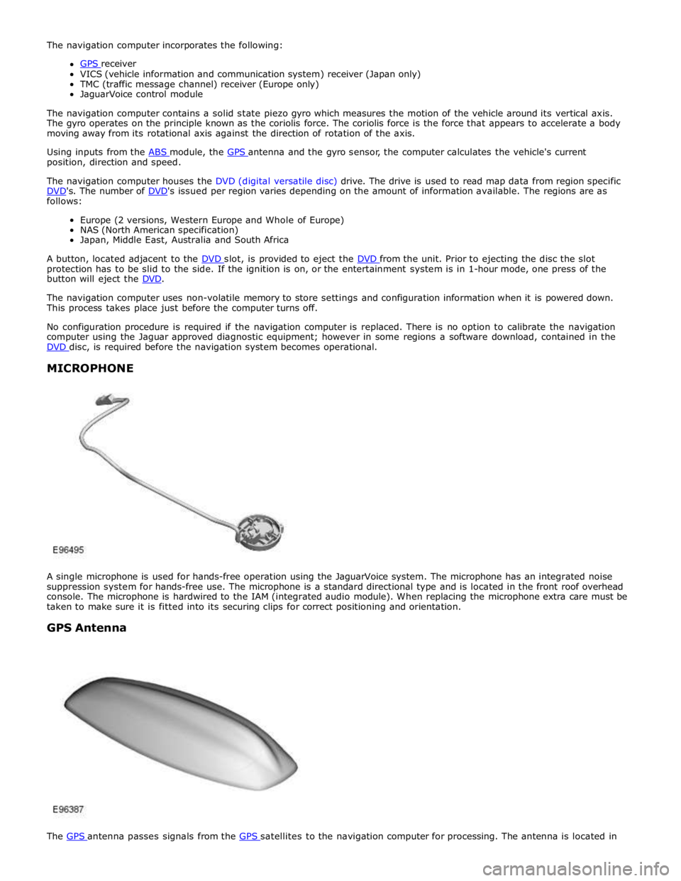
A single microphone is used for hands-free operation using the JaguarVoice system. The microphone has an integrated noise
suppression system for hands-free use. The microphone is a standard directional type and is located in the front roof overhead
console. The microphone is hardwired to the IAM (integrated audio module). When replacing the microphone extra care must be
taken to make sure it is fitted into its securing clips for correct positioning and orientation.
GPS Antenna
The GPS antenna passes signals from the GPS satellites to the navigation computer for processing. The antenna is located in
Page 1981 of 3039
Navigation Destination, stored locations, navigation setup, route options Vehicle
Security, parking, valet mode, trip computer, clock, brightness, contrast, system settings, vehicle settings, display settings The screen is a touch sensitive 7 inch LCD (liquid crystal display) VGA screen containing 800 x 480 pixels in a 15:9 format. The
screen processes its own video for system operation but receives the navigation graphics from the navigation computer.
Steering Wheel Controls
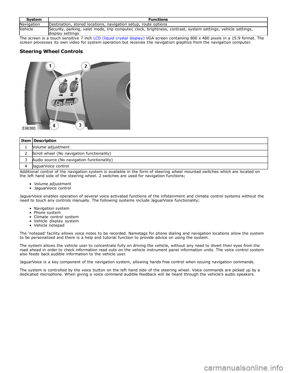
Item Description 1 Volume adjustment 2 Scroll wheel (No navigation functionality) 3 Audio source (No navigation functionality) 4 JaguarVoice control Additional control of the navigation system is available in the form of steering wheel mounted switches which are located on
the left hand side of the steering wheel. 2 switches are used for navigation functions;
Volume adjustment
JaguarVoice control
JaguarVoice enables operation of several voice activated functions of the infotainment and climate control systems without the
need to touch any controls manually. The following systems include JaguarVoice functionality;
Navigation system
Phone system
Climate control system
Vehicle display system
Vehicle notepad
The 'notepad' facility allows voice notes to be recorded. Nametags for phone dialing and navigation locations allow the system
to be personalized and there is a help and tutorial function to provide advice on using the system.
The system allows the vehicle user to concentrate fully on driving the vehicle, without any need to divert their eyes from the
road ahead in order to check information read outs on the vehicle instrument panel information units. The voice control system
also feeds back audible information to the vehicle user.
JaguarVoice is a key component of the navigation system, allowing hands free control when issuing navigation commands.
The system is controlled by the voice button on the left hand side of the steering wheel. Voice commands are picked up by a
dedicated microphone. When giving a voice command audible feedback will be heard through the vehicle’s audio speakers.
Page 2013 of 3039
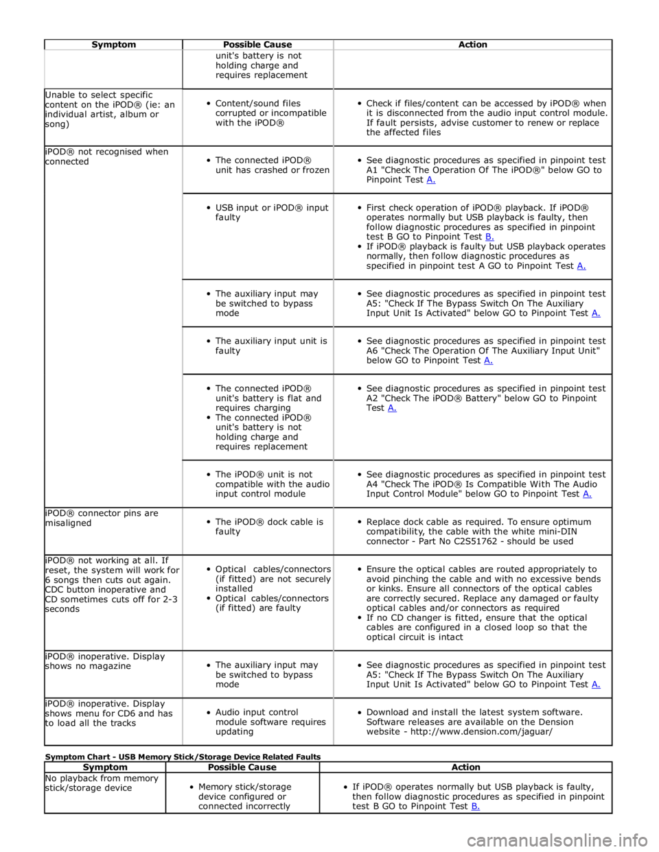
Symptom Possible Cause Action unit's battery is not
holding charge and
requires replacement Unable to select specific
content on the iPOD® (ie: an
individual artist, album or
song)
Content/sound files
corrupted or incompatible
with the iPOD®
Check if files/content can be accessed by iPOD® when
it is disconnected from the audio input control module.
If fault persists, advise customer to renew or replace
the affected files iPOD® not recognised when
connected
The connected iPOD®
unit has crashed or frozen
See diagnostic procedures as specified in pinpoint test
A1 "Check The Operation Of The iPOD®" below GO to
Pinpoint Test A.
USB input or iPOD® input
faulty
First check operation of iPOD® playback. If iPOD®
operates normally but USB playback is faulty, then
follow diagnostic procedures as specified in pinpoint
test B GO to Pinpoint Test B. If iPOD® playback is faulty but USB playback operates
normally, then follow diagnostic procedures as
specified in pinpoint test A GO to Pinpoint Test A.
The auxiliary input may
be switched to bypass
mode
See diagnostic procedures as specified in pinpoint test
A5: "Check If The Bypass Switch On The Auxiliary
Input Unit Is Activated" below GO to Pinpoint Test A.
The auxiliary input unit is
faulty
See diagnostic procedures as specified in pinpoint test
A6 "Check The Operation Of The Auxiliary Input Unit"
below GO to Pinpoint Test A.
The connected iPOD®
unit's battery is flat and
requires charging
The connected iPOD®
unit's battery is not
holding charge and
requires replacement
See diagnostic procedures as specified in pinpoint test
A2 "Check The iPOD® Battery" below GO to Pinpoint
Test A.
The iPOD® unit is not
compatible with the audio
input control module
See diagnostic procedures as specified in pinpoint test
A4 "Check The iPOD® Is Compatible With The Audio
Input Control Module" below GO to Pinpoint Test A. iPOD® connector pins are
misaligned
The iPOD® dock cable is
faulty
Replace dock cable as required. To ensure optimum
compatibility, the cable with the white mini-DIN
connector - Part No C2S51762 - should be used iPOD® not working at all. If
reset, the system will work for
6 songs then cuts out again.
CDC button inoperative and
CD sometimes cuts off for 2-3
seconds
Optical cables/connectors
(if fitted) are not securely
installed
Optical cables/connectors
(if fitted) are faulty
Ensure the optical cables are routed appropriately to
avoid pinching the cable and with no excessive bends
or kinks. Ensure all connectors of the optical cables
are correctly secured. Replace any damaged or faulty
optical cables and/or connectors as required
If no CD changer is fitted, ensure that the optical
cables are configured in a closed loop so that the
optical circuit is intact iPOD® inoperative. Display
shows no magazine
The auxiliary input may
be switched to bypass
mode
See diagnostic procedures as specified in pinpoint test
A5: "Check If The Bypass Switch On The Auxiliary
Input Unit Is Activated" below GO to Pinpoint Test A. iPOD® inoperative. Display
shows menu for CD6 and has
to load all the tracks
Audio input control
module software requires
updating
Download and install the latest system software.
Software releases are available on the Dension
website - http://www.dension.com/jaguar/ Symptom Chart - USB Memory Stick/Storage Device Related Faults
Symptom Possible Cause Action No playback from memory
stick/storage device
Memory stick/storage
device configured or
connected incorrectly
If iPOD® operates normally but USB playback is faulty,
then follow diagnostic procedures as specified in pinpoint
test B GO to Pinpoint Test B.
Page 2017 of 3039
Is the USB extension cable securely pushed into the USB connection port on the audio input control module
Yes
Replace the USB extension cable
No
Secure connections and retest B4: CHECK THE CAPACITY OF THE MEMORY STICK/STORAGE DEVICE
NOTE: The higher the capacity of the memory stick is the longer it takes to register with the audio input control module
and power up. The maximum permitted capacity is 8 Gigabytes 1 Check the storage capacity of the memory stick/storage device does not exceed 8 Gigabytes Is the storage capacity of the memory stick/storage device 8 Gigabytes or less?
Yes
High capacity devices may require longer to register and should be allowed up to two minutes to power up
following connection to the USB port. If memory stick fails to power up after two minutes, suspect a
faulty memory stick GO to B2. or USB extension cable GO to B3. No
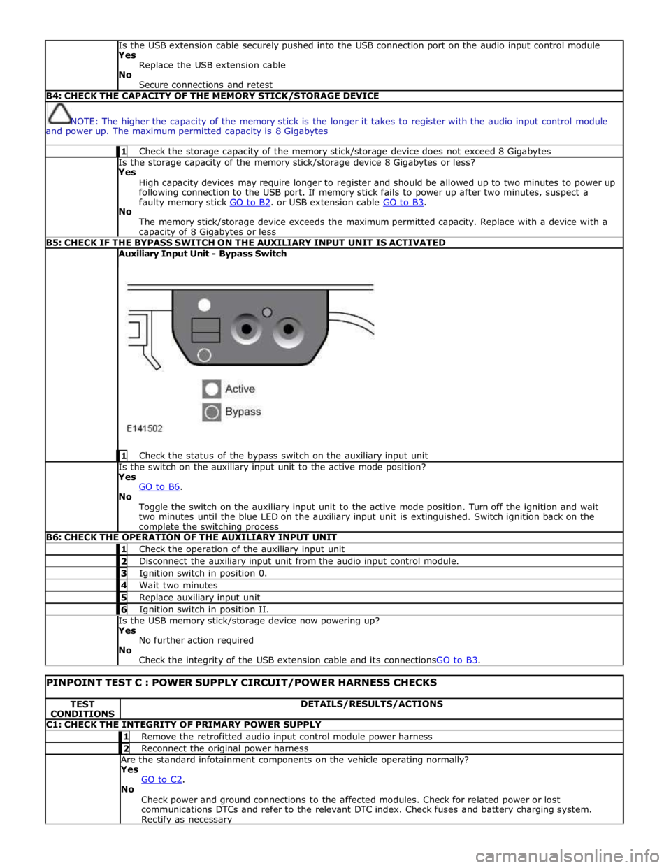
The memory stick/storage device exceeds the maximum permitted capacity. Replace with a device with a capacity of 8 Gigabytes or less B5: CHECK IF THE BYPASS SWITCH ON THE AUXILIARY INPUT UNIT IS ACTIVATED Auxiliary Input Unit - Bypass Switch
1 Check the status of the bypass switch on the auxiliary input unit Is the switch on the auxiliary input unit to the active mode position?
Yes
GO to B6. No
Toggle the switch on the auxiliary input unit to the active mode position. Turn off the ignition and wait
two minutes until the blue LED on the auxiliary input unit is extinguished. Switch ignition back on the complete the switching process B6: CHECK THE OPERATION OF THE AUXILIARY INPUT UNIT 1 Check the operation of the auxiliary input unit 2 Disconnect the auxiliary input unit from the audio input control module. 3 Ignition switch in position 0. 4 Wait two minutes 5 Replace auxiliary input unit 6 Ignition switch in position II. Is the USB memory stick/storage device now powering up?
Yes
No further action required
No
Check the integrity of the USB extension cable and its connectionsGO to B3.
PINPOINT TEST C : POWER SUPPLY CIRCUIT/POWER HARNESS CHECKS TEST
CONDITIONS DETAILS/RESULTS/ACTIONS C1: CHECK THE INTEGRITY OF PRIMARY POWER SUPPLY 1 Remove the retrofitted audio input control module power harness 2 Reconnect the original power harness Are the standard infotainment components on the vehicle operating normally?
Yes
GO to C2. No
Check power and ground connections to the affected modules. Check for related power or lost
communications DTCs and refer to the relevant DTC index. Check fuses and battery charging system. Rectify as necessary
Page 2027 of 3039
by Field Effect Transistors (FET's). The FET's can detect overloads and short circuits and respond to heat generated by
increased current flow caused by a short circuit.
On a normal conventionally protected circuit this would cause a fuse to blow. The FET's respond to the heat increase and
disconnect the power supply to the affected circuit. When the fault is rectified or the FET has cooled, the FET will reset and
operate the circuit normally. If the fault persists the FET will cycle, disconnecting and reconnecting the power supply.
The CJB and the RJB store fault codes which can be retrieved using a Jaguar approved diagnostic system. The fault code will identify that there is a fault on a particular output circuit which will assist with fault diagnosis and detection.
Alarm Indications
The exterior lighting system is used for alarm arm and disarm requests to show alarm system status.
When the driver locks and arms the vehicle, a visual indication of a successful lock and arm request is displayed to the driver
by a single flash of the hazard flashers. If the vehicle is superlocked, then the hazard flashers will flash a second time (200 ms
off and 200 ms on) to confirm the superlock request.
If the alarm is activated, the hazard flashers are operated for 10, 30 second cycles of 200 ms on and 200 ms off, with a 10
second delay between each cycle.
NOTE: On North American Specification (NAS) vehicles, the delay between the cycle when the alarm is activated is 60
seconds.
Lights on Warning
When the ignition is in the off power mode 0 or accessory power mode 4 and the lighting control switch is in the side lamp or
headlamp position, a warning chime will sound if the driver's door is opened. This indicates to the driver that the exterior
lights have been left switched on.
The chime is generated from the instrument cluster sounder on receipt of a lights on signal, a driver's door open signal and an
ignition off power mode 0 or accessory power mode 4 signal via a medium speed CAN bus signal from the CJB. Headlamp Timer
The RJB controls the headlamp timer function which allows the headlamps to remain on for a period of time after leaving the vehicle. This is a driver convenience feature which illuminates the driveway after leaving the vehicle.
To operate the timer function the lighting control switch must be in one of the three headlamp timer positions when the
ignition status is changed from ignition on power mode 6 to the off power mode 0. The timer function will then be initiated and
the low beam headlamps will be illuminated for the selected timer period.
NOTE: If the lighting switch is in the AUTO position, the headlamp timer will not function when the ignition is changed to
off power mode 0.
When the lighting control switch is in the autolamp exit delay position, the lighting control switch reference voltage flows
through 4 of the resistors. The returned signal voltage is detected by the instrument cluster which outputs a message on the
medium speed CAN bus to the RJB that autolamps has been selected.
Depending on the selected exit delay position, the reference voltage to the autolamp exit delay switch is routed through 3, 2
or 1 resistors which is detected by the instrument cluster. The cluster outputs a message on the medium speed CAN bus to the RJB that autolamp exit delay period has been selected at 30, 60 or 120 seconds respectively. Crash Signal Activation
When a crash signal is transmitted from the RCM (restraints control module), the RJB activates the hazard flashers. The hazard flashers continue to operate until the ignition is in the off power mode 0 or accessory power mode 6. Once this ignition state
has occurred, the RCM will cease to transmit the crash signal.
LIGHTING CONTROL SWITCH
The instrument cluster outputs 2 reference voltages to the rotary lighting control switch; one feed being supplied to the light
selection function of the switch and the second feed being supplied to the auto headlamp exit delay function. The switch
position is determined by instrument cluster by the change in returned signal voltage which is routed through up to 4 resistors
in series depending on the selection made.
OFF - When the lighting control switch is in the off position, the reference voltage flows through 1 of the resistors. The
returned signal voltage is detected by the instrument cluster which outputs a message on the medium speed CAN bus to the CJB that no lighting selection is made. The reference voltage to the auto headlamp exit delay switch is routed through 4 resistors which is detected by the instrument cluster which outputs a message on the medium speed CAN bus to the CJB that auto headlamp or exit delay has not been selected.
SIDE LAMPS - When the lighting control switch is in the side lamp position, the reference voltage flows through 2 of the
resistors. The returned signal voltage is detected by the instrument cluster which outputs a message on the medium speed
CAN bus to the CJB to activate the side lamps. The reference voltage to the autolamp exit delay switch is routed through 4 resistors which is detected by the instrument cluster which outputs a message on the medium speed CAN bus to the CJB that auto headlamp or exit delay has not been selected.
HEADLAMPS - When the lighting control switch is in the headlamp position, the reference voltage flows through 3 of the
Page 2033 of 3039
Halogen Low/high Beam Headlamp
The halogen low/high beam headlamp uses a projector lens, similar to the xenon headlamp. The projector module comprises
an ellipsoidal lens and a reflector. The projector reflector collects the light produced by the halogen bulb and projects the light
into a focal plane containing a shield. The contour of the shield is projected onto the road by the lens. The low/high beam
bulbs are quartz halogen and are retained in the headlamp unit with conventional wire retaining clips.
A tourist lever mechanism is located on the right hand side of the projector module. This mechanism moves a flap to blank off
a portion of the beam spread to enable the vehicle to be driven in opposite drive hand markets without applying blanking
decals to the headlamp lens. The beam is changed by removing the access cover at the rear of the lamp assembly and moving
a small lever located near the bulb holder, at the side of the projector.
Halogen High Beam Headlamp - Xenon and Halogen
The xenon and halogen headlamps use a complex surface reflector for the halogen fill in high beam lamp only lighting unit,
which is of the same design on both headlamp types. This type of reflector has the reflector divided into separate parabolic
segments, with each segment having a different focal length.
The high beam headlamp bulbs are quartz halogen and are retained in the headlamp unit with conventional wire retaining
clips.
Cornering Lamps
NOTE: The cornering lamps are not fitted to NAS vehicles.
The cornering lamps are an optional feature designed to illuminate the direction of travel when cornering at low speeds. The
design of the lens projects a spread of light from the vehicle at approximately 45 degrees to the vehicle axis. The cornering
lamp is incorporated into the headlamp assembly and shares the same housing as the low beam headlamp. The cornering lamp
uses a 35W Halogen H8 bulb which is permanently located in an integral holder which is connected on the headlamp housing.
The holder is located in an aperture in the headlamp housing and rotated to lock. The bulb is accessible via a removable cover
on the base of the headlamp housing.
The cornering lamps are controlled by the LH steering column multifunction switch with the lighting control switch in the headlamp position and the ignition in power mode 6. The cornering lamps are supplied power via the ignition circuit to ensure
that they do not function with the headlamp delay feature. The cornering lamps are deactivated if the vehicle speed exceeds
25 mph (40 km/h). Only one cornering lamp will illuminate at any one time. If the left hand turn signal indicators are selected
on, the left hand cornering lamp will be illuminated and vice versa, providing the vehicle speed and lighting control switch
positions are correct.
Static Bending Lamps
NOTE: The static bending lamps are not fitted to NAS vehicles.
The static bending lamps are designed to illuminate the direction of travel when cornering at low speeds. The static bending
lamp functionality, which is controlled by the CJB and the headlamp leveling module, operates using inputs from the steering angle sensor and vehicle speed information from the ABS (anti-lock brake system) module. The static bending lamp is
incorporated into the headlamp assembly and shares the same housing as the low beam headlamp. The design of the lens
projects a spread of light from the vehicle at approximately 45 degrees to the vehicle axis. The static bending lamp uses a
35W Halogen H8 bulb which locates in a holder which is connected via wires to the main connector on the headlamp housing.
The holder is located in an aperture in the headlamp housing and rotated to lock. The bulb is accessible via a removable cover
at the rear of the headlamp housing.
The static bending lamps operate with a steering angle sensor CAN bus signal which is received by the CJB. The CJB monitors this signal and vehicle speed and activates the static bending lamp bulb. When the operation parameters of the lamp are
reached, the CJB fades the static bending lamp bulb on using a PWM (pulse width modulation) voltage over a period of approximately 2 seconds. When the lamp is switched off, the CJB fades the bulb off by decreasing the PWM voltage in a linear manner depending on steering angle and vehicle speed. The cornering lamps can only be active for a maximum of 3 minutes.
NOTE: Static bending lamps only operate when the transmission is in DRIVE or in SPORT.
Turn Signal Indicators
The turn signal indicator lamp is incorporated into the outer part of the headlamp assembly. The turn signal indicator lamp
uses a PY21W bayonet orange colored bulb in ROW markets, a S8W 27/7W wedge bulb is used in NAS markets. The bulb is
fitted into a holder which connects with contacts in the headlamp housing. The holder is fitted into an aperture in the
headlamp housing and rotated to lock into position.
When active, the turn signal indicator lamps will flash at a frequency cycle of 380ms on and 380ms off. If a bulb fails, the
remaining turn signal lamps bulbs continue to flash at normal speed. The turn signal indicators in the instrument cluster will
flash at double speed to indicate the bulb failure to the driver.
Side Lamps
The side lamp is located between the headlamp projector module and the high bean headlamp. The side lamp uses a W5W
wedge fitting bulb which locates in a holder which connected via wires to the main connector on the headlamp housing. The
holder is a push fit into a receptacle in the headlamp housing. The bulb is accessible by removal of the inner cover on the rear
of the headlamp housing. Access to the bulb requires removal of the headlamp from the vehicle. The side lamps are operated
by selecting side lamps or headlamps on the lighting control switch. The side lamps are functional at all times and are
Page 2034 of 3039
dependant on a particular ignition mode status. The side lamps will also be illuminated when the lighting control switch is in
the AUTO position and a 'lights on' signal is received by the CJB from the rain/light sensor Side Marker Lamps (NAS only)
The side marker lamp is located in the outer part of the headlamp assembly. The side marker lamp uses a W5W wedge fitting
bulb. The bulb is fitted into a holder which connects with contacts in the headlamp housing. The holder is fitted into an
aperture which connects with contacts in the headlamp housing. The side marker lamp is active at all times when the side
lamps are active.
AUTOMATIC HEADLAMP OPERATION
The automatic headlamp function is a driver assistance system. The driver can override the system operation by selection of
side lamp or headlamp on if the ambient light conditions require front and rear lighting to be active. The automatic headlamp
system uses a light sensor and the CJB, which are connected via a LIN (local interconnect network) bus to control the headlamp functionality. The light sensor is incorporated in the rain/light sensor located on the inside of the windshield, below
the rear view mirror. The wiper system also uses the rain/light sensor for automatic wiper operation.
The light sensor measures the ambient light around the vehicle in a vertical direction and also the angular light level from the
front of the vehicle. The rain/light sensor uses vehicle speed signals, wiper switch position and the park position of the front
wipers to control the system. The automatic headlamp operation uses ambient light levels which are monitored by photodiode
incorporated in the rain/light sensor. The rain/light sensor sends a lights on/off request to the CJB on the LIN bus, which responds by switching on the low beam headlamps, front side lamps and rear tail lamps. The automatic headlamps are
activated under the following conditions:
Twilight
Darkness
Rain
Snow
Tunnels
Underground or multistoried car parks.
Operation of the automatic headlamps requires the ignition to be in ignition mode 6, the lighting control switch to be in the
'AUTO' position and a lights on request signal from the light sensor. If the rain sensor signal activates the fast speed wipers,
the low beam headlamps are activated, providing the lighting control switch is in the 'AUTO' position.
HEADLAMP LEVELING
Headlamp leveling provides for the adjustment of the vertical aim of the headlamps. The leveling system is primarily required
to minimise glare to other road users when a heavy load is in the rear of the vehicle. Two systems of headlamp leveling are
available; manual and static dynamic.
Manual Headlamp Leveling
The manual system uses a thumbwheel rheostat to adjust the vertical alignment of the headlamps to compensate for differing
vehicle loading. The rotary thumbwheel is located on the auxiliary lighting switch, adjacent to the illumination dimmer
thumbwheel. Three positions are available to adjust the headlamps to a position to prevent glare to other road users.
Static Dynamic Headlamp Leveling
The static dynamic headlamp leveling system uses the following components:
Front and rear vehicle height sensors
Two headlamp leveling, vertical adjustment motors
Headlamp leveling module
Ignition in mode 6
Vehicle speed information from ABS module.
The static dynamic system uses height sensors fitted to the front and rear suspension and a headlamp leveling module which
periodically monitors the vehicle attitude and adjusts the headlamp vertical alignment accordingly.
Static dynamic headlamp leveling is controlled by a headlamp leveling module located in the lower instrument panel, behind
the glovebox.
The height sensors are both located on the RH side of the vehicle. The front sensor is attached to the front suspension lower arm with a strap and to the front sub frame with a bracket and 2 bolts. The rear sensor is attached to the rear suspension
upper control arm with a cable tied clip and to the rear sub frame with a bracket and 2 bolts. Each sensor has 3 connections to
the headlamp leveling module; power, ground and signal.
DAYTIME RUNNING LAMPS (DRL)
Refer to DRL section for details. Refer to: Daytime Running Lamps (DRL) (417-04 Daytime Running Lamps (DRL), Description and Operation).
REAR LAMP ASSEMBLY
The rear lamp assembly is a 2 piece unit, with one part located in the rear quarter panel and the second part attached to the
luggage compartment lid. The outer rear lamp assembly is located in a recess in the vehicle body. The lamp is secured with 2
studs inboard studs on the lamp body which are secured to the vehicle body with 2 nuts. A third outboard stud and nut secures
Page 2036 of 3039
Rear Fog Lamp
The rear fog lamps are located in separate units attached to the luggage compartment lid. The rear fog lamps each use 3 high
intensity LED's. The fog lamp locates in a recess in the luggage compartment lid has a seal to prevent the ingress of water into the luggage compartment. The lamp is secured in the recess with a metal securing clip. The rear fog lamp is activated
using a button located on the auxiliary lighting switch in the instrument panel.
LICENCE PLATE LAMPS
Two licence plate lamps are located in the luggage compartment lid trim finisher. One is located adjacent to the emergency
luggage compartment lid release key barrel cover and the other is adjacent to the rear view camera (if fitted). The licence plate
lamps are active at all times when the side lamps are operating. Each lamp can be removed from the finisher by inserting a
wide, flat screwdriver blade or similar tool in a slot between the lamp lens and the finisher and gently levering the lamp from
the surround. The bulb is a push fit in a holder which in turn is a press fit in the lamp housing.
HIGH MOUNTED STOP LAMP
The high mounted stop lamp is located at the bottom of the rear windshield. The lamp is secured to a bezel in the parcel shelf
with 2 screws.
The high mounted stop lamp uses 12, red colored LED's which illuminate through a clear lens. The high mounted stop lamp functionality is the same as that described for the stop lamps.
TURN SIGNAL INDICATOR SIDE REPEATER LAMPS
The turn signal indicator side repeaters are located in each door mirror. On vehicles from 10MY the lamp is an LED unit which illuminates in an orange color. The LED unit is secured to the mirror bezel with 2 screws and is connected to the mirror wiring harness with a 2 pin connector.
The side repeaters have the same functionality and operate in conjunction with the front and rear turn signal indicators and
the hazard warning flashers.
HAZARD FLASHERS
The hazard flashers are activated by a non-latching switch located in the switch pack located in the center of the instrument
panel. The hazard flashers operate at all times when selected and operate independent of the ignition mode.
When the hazard flashers are selected on by the driver, a ground path is momentarily completed to the CJB which activates the front and rear and side repeater turn signal indicators. A second press of the switch is sensed by the CJB and the hazard flasher are deactivated. When the hazard flashers are active, they override any request for turn signal indicator operation.
The hazard flashers can also be activated by a crash signal from the RCM. Refer to: Air Bag and Safety Belt Pretensioner Supplemental Restraint System (SRS) (501-20B Supplemental Restraint System, Description and Operation).