2010 JAGUAR XFR tow
[x] Cancel search: towPage 2542 of 3039
On vehicles with headlamp powerwash, each headlamp assembly is fitted with a headlamp powerwasher. The powerwasher is
located on the underside of the headlamp assembly. The powerwasher is located in a clip at the front of the headlamp and
secured with 2 self tapping screws to the headlamp body.
The powerwasher is a telescopic unit which extends forwards from the headlamp assembly under washer fluid pressure
supplied by the headlamp powerwash pump. When the pump pressure decreases the powerwasher is automatically retracted
back into the housing. The outer end of the powerwasher is fitted with a trim which blends the powerwasher into the headlamp
when it is not operating. The powerwasher has two washer jets which direct washer fluid under high pressure onto the
headlamp lens when the powerwasher is extended.
RAIN/LIGHT SENSOR
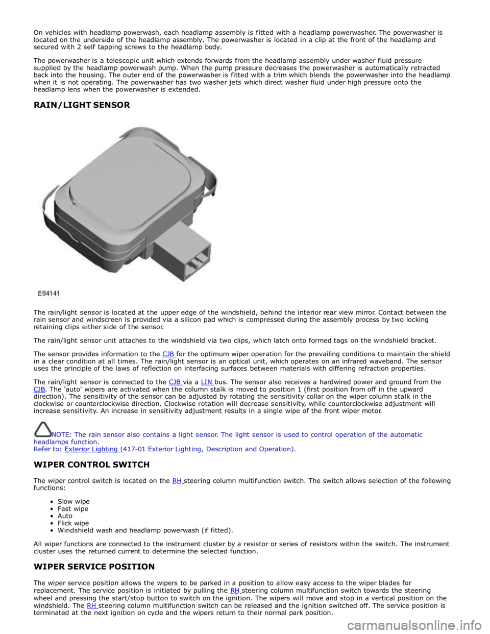
The rain/light sensor is located at the upper edge of the windshield, behind the interior rear view mirror. Contact between the
rain sensor and windscreen is provided via a silicon pad which is compressed during the assembly process by two locking
retaining clips either side of the sensor.
The rain/light sensor unit attaches to the windshield via two clips, which latch onto formed tags on the windshield bracket.
The sensor provides information to the CJB for the optimum wiper operation for the prevailing conditions to maintain the shield in a clear condition at all times. The rain/light sensor is an optical unit, which operates on an infrared waveband. The sensor
uses the principle of the laws of reflection on interfacing surfaces between materials with differing refraction properties.
The rain/light sensor is connected to the CJB via a LIN bus. The sensor also receives a hardwired power and ground from the CJB. The 'auto' wipers are activated when the column stalk is moved to position 1 (first position from off in the upward direction). The sensitivity of the sensor can be adjusted by rotating the sensitivity collar on the wiper column stalk in the
clockwise or counterclockwise direction. Clockwise rotation will decrease sensitivity, while counterclockwise adjustment will
increase sensitivity. An increase in sensitivity adjustment results in a single wipe of the front wiper motor.
NOTE: The rain sensor also contains a light sensor. The light sensor is used to control operation of the automatic
headlamps function.
Refer to: Exterior Lighting (417-01 Exterior Lighting, Description and Operation).
WIPER CONTROL SWITCH
The wiper control switch is located on the RH steering column multifunction switch. The switch allows selection of the following functions:
Slow wipe
Fast wipe
Auto
Flick wipe
Windshield wash and headlamp powerwash (if fitted).
All wiper functions are connected to the instrument cluster by a resistor or series of resistors within the switch. The instrument
cluster uses the returned current to determine the selected function.
WIPER SERVICE POSITION
The wiper service position allows the wipers to be parked in a position to allow easy access to the wiper blades for
replacement. The service position is initiated by pulling the RH steering column multifunction switch towards the steering wheel and pressing the start/stop button to switch on the ignition. The wipers will move and stop in a vertical position on the
windshield. The RH steering column multifunction switch can be released and the ignition switched off. The service position is terminated at the next ignition on cycle and the wipers return to their normal park position.
Page 2636 of 3039
Supplemental Restraint System - Driver Air Bag Module
Removal and Installation Published: 11-May-2011
Removal
WARNING: Refer to: Supplemental Restraint System (SRS) Health and Safety Precautions (100-00, Description and
Operation).
NOTE: Removal steps in this procedure may contain installation details.
1. Refer to: Battery Disconnect and Connect (414-01, General Procedures).
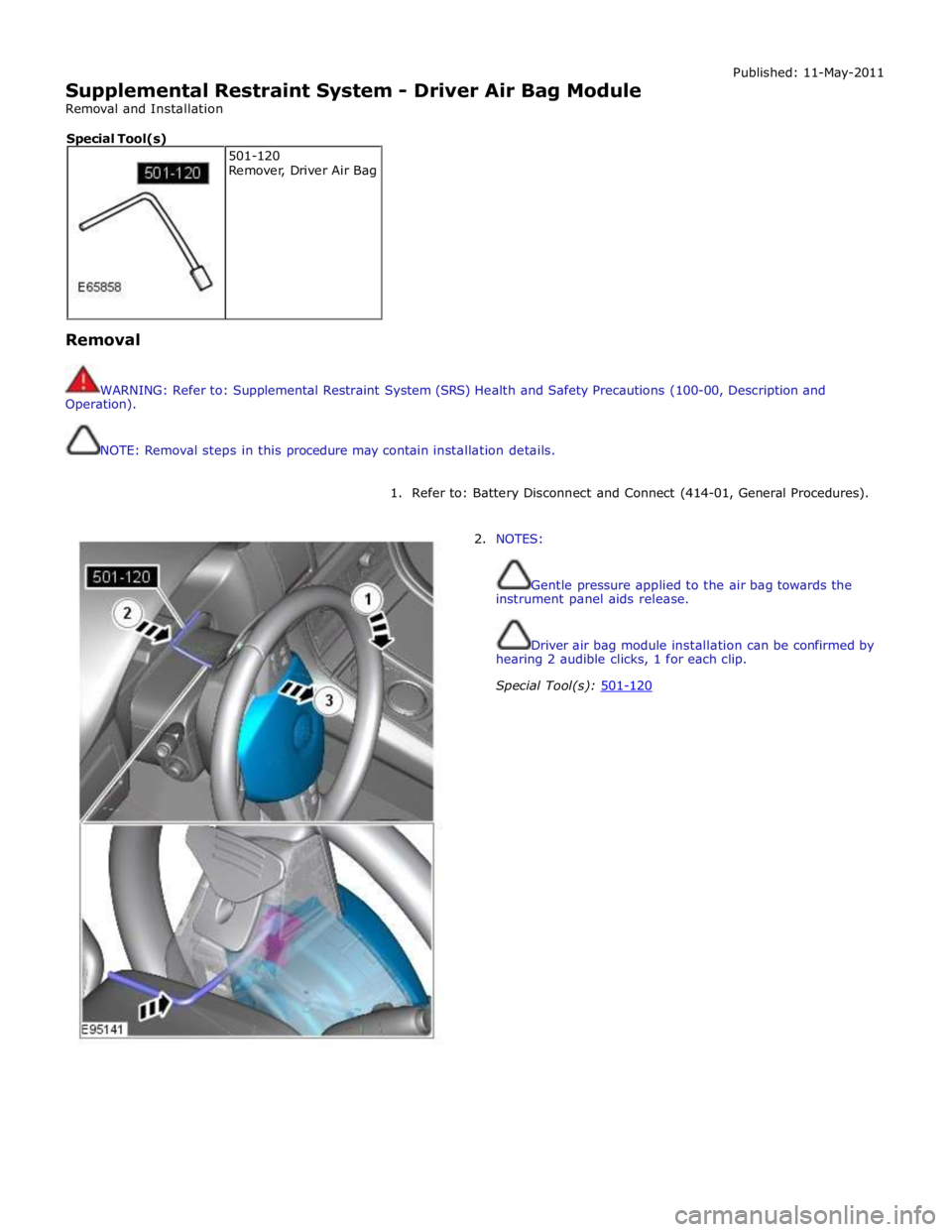
2. NOTES:
Gentle pressure applied to the air bag towards the
instrument panel aids release.
Driver air bag module installation can be confirmed by
hearing 2 audible clicks, 1 for each clip.
Special Tool(s): 501-120 501-120
Remover, Driver Air Bag Special Tool(s)
Page 2735 of 3039
Side windows
In the case of side windows, the same problems can arise as for a windscreen. The same corrective actions must therefore be
used.
Door seal
Diagnosis:
- Water ingress in the lower part of the interior door trim or in the rocker panel area.
Cause:
- The water shield fitted behind the interior door trim exists to drain off water that has entered the door via the
drainage holes, either downwards or outwards. If the water shield seal is damaged or has been fitted incorrectly,
then water can get into the passenger compartment.
- In addition to this, the drainage holes can become clogged with leaves, dirt or excess cavity protection agents.
Water gathers in the door and ingresses into the passenger compartment.
- Check water shield for damage or correct fitting.
- If the water shield needs to be re-bonded, then approved seam sealer should be used.
- Before the water shield is installed, the drainage holes must be checked for unhindered flow.
Door seals
Diagnosis:
- Ingress of water into the rocker panel area
Cause:
- Insufficient clamping load between seal and door.
Corrective action:
NOTE: When adjusting the clamping load, the profile alignment of the relevant components must always be taken
into consideration.
NOTE: Do not realign the flange too far in the direction of the door, as this can reduce the bearing surface of the
seal to the door.
- Check clamping load:
- The easiest way to check the clamping load of a seal to the respective bearing surface is by means of a paper
strip test. This consists of trapping strips of paper at various points between the door and the seal, and fully
closing the door. If it is possible to pull out the paper with no great resistance, then the clamping load is too
low.
- Adjust the clamping load:
- The clamping load is normally adjusted using the striker. When doing so, the edge alignment from the door to
the side panel, or from the front door to the rear door must be taken into account.
- Another setting method is to realign the panel flange for the seal mounting. The clamping load is increased by
moving the flange towards the door.
- Check the bearing surface:
- Apply chalk evenly to the surface of the seal. Evenly coat the bearing surface of the door with Vaseline.
- Close the door fully, the lock must engage. Open the door. The imprint of the chalk (bearing surface) can be
identified in the film of Vaseline.
- The bearing surface should be at least 5mm across at all points.
Other causes:
- The door seal must completely seal the door where it meets the bodywork.
- Water can ingress directly or indirectly into the interior of the vehicle if the seal is damaged at any point.
Corrective action:
- A damaged or worn door seal must always be renewed in full.
- When renewing the seal, the following must be taken into account:
- Always fit the seal first in the area of the narrow radii (corner points).
- Next, secure the seal to the flange evenly by tapping lightly with a rubber hammer. The installed seal must not
be kinked at any point.
NOTE: The prescribed length of a seal must not be shortened.
Other cause:
- The door seal is attached to the welded flange all the way round. If this welded flange is uneven or damaged at
any point (usually in areas with small radii) then this point could be subject to leaks.
- A stretched seal carrier can also cause a leak.
- In both cases, water gets into the vehicle interior under the seal carrier.
Corrective action:
- Align the deformed welded flange using a hammer and anvil block, prevent and, if necessary, repair any paint
damage.
Sliding roof/tilting roof
Diagnosis:
- Ingress of water at sliding roof aperture
Cause:
- The sliding roof/tilting roof is installed in a water trap. The water drains off via the water trap, water drain holes
and drain hoses. The drain hoses lead downwards on both sides via the A-pillar and B-pillar.
- The drain holes or drain hoses can become clogged with leaves, dirt, underbody protection and so on.
Corrective action:
Page 2745 of 3039
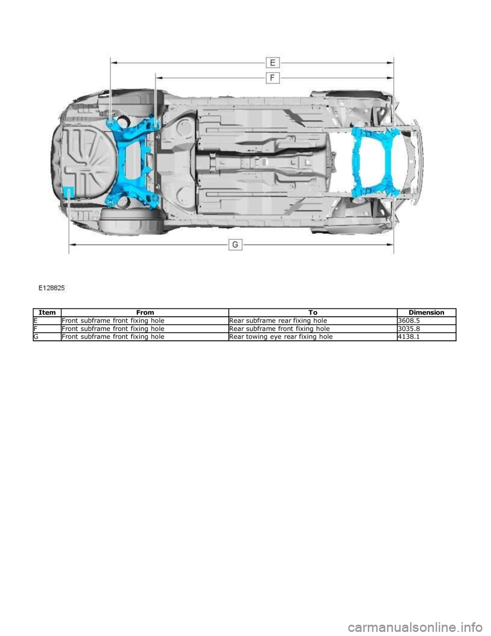
E Front subframe front fixing hole Rear subframe rear fixing hole 3608.5 F Front subframe front fixing hole Rear subframe front fixing hole 3035.8 G Front subframe front fixing hole Rear towing eye rear fixing hole 4138.1
Page 2746 of 3039
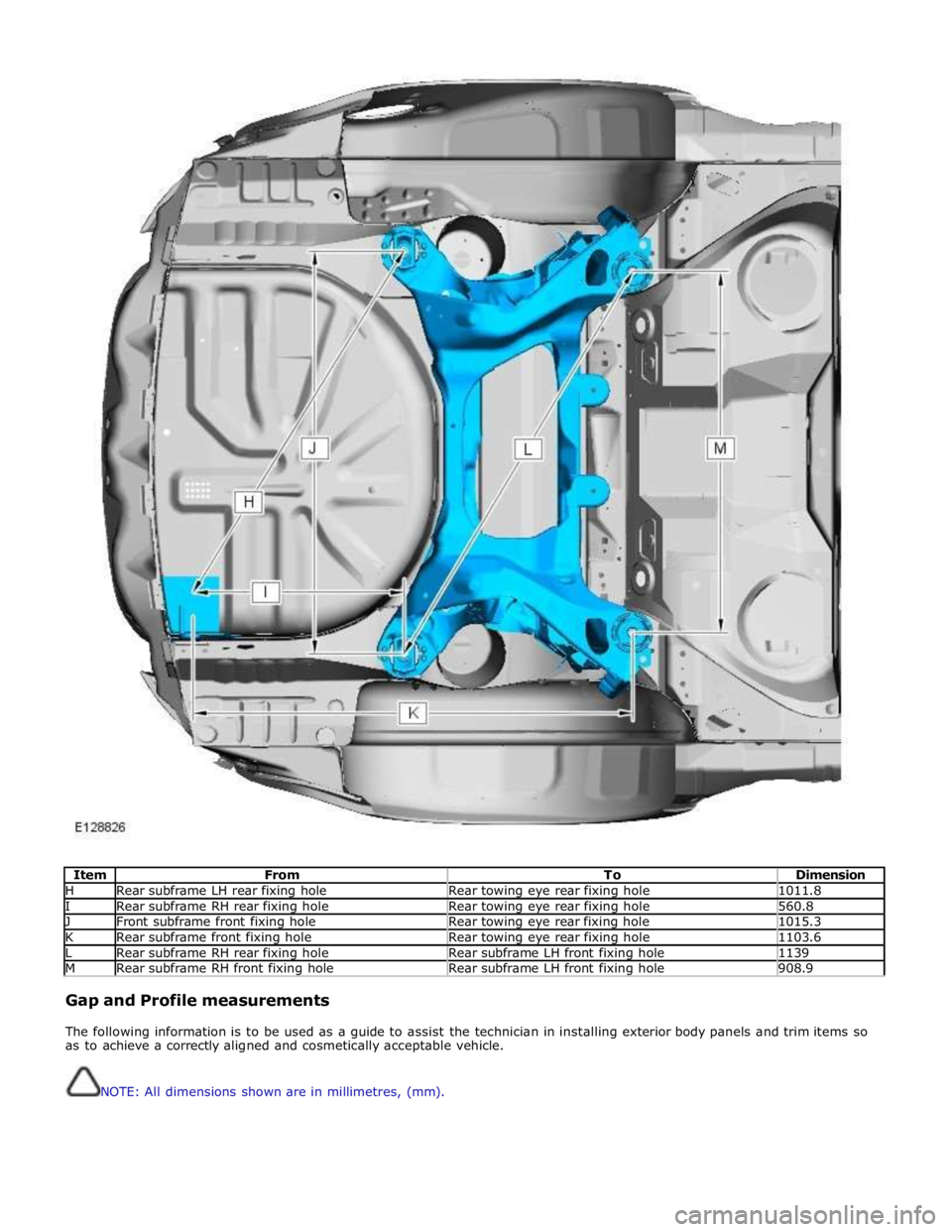
Item From To Dimension H Rear subframe LH rear fixing hole Rear towing eye rear fixing hole 1011.8 I Rear subframe RH rear fixing hole Rear towing eye rear fixing hole 560.8 J Front subframe front fixing hole Rear towing eye rear fixing hole 1015.3 K Rear subframe front fixing hole Rear towing eye rear fixing hole 1103.6 L Rear subframe RH rear fixing hole Rear subframe LH front fixing hole 1139 M Rear subframe RH front fixing hole Rear subframe LH front fixing hole 908.9
Gap and Profile measurements
The following information is to be used as a guide to assist the technician in installing exterior body panels and trim items so
as to achieve a correctly aligned and cosmetically acceptable vehicle.
NOTE: All dimensions shown are in millimetres, (mm).
Page 2974 of 3039
Rear End Sheet Metal Repairs - Rear Side Member Section
Removal and Installation
Removal Published: 11-May-2011
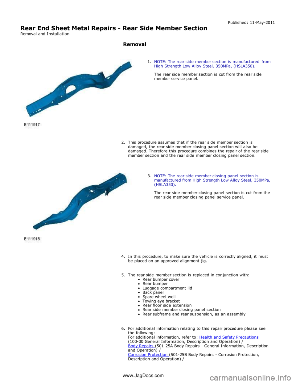
1. NOTE: The rear side member section is manufactured from
High Strength Low Alloy Steel, 350MPa, (HSLA350).
The rear side member section is cut from the rear side
member service panel.
2. This procedure assumes that if the rear side member section is
damaged, the rear side member closing panel section will also be
damaged. Therefore this procedure combines the repair of the rear side
member section and the rear side member closing panel section.
3. NOTE: The rear side member closing panel section is
manufactured from High Strength Low Alloy Steel, 350MPa,
(HSLA350).
The rear side member closing panel section is cut from the
rear side member closing panel service panel.
4. In this procedure, to make sure the vehicle is correctly aligned, it must
be placed on an approved alignment jig.
5. The rear side member section is replaced in conjunction with:
Rear bumper cover
Rear bumper
Luggage compartment lid
Back panel
Spare wheel well
Towing eye bracket
Rear floor side extension
Rear side member closing panel section
Rear subframe and rear suspension, as an assembly
6. For additional information relating to this repair procedure please see
the following:
For additional information, refer to: Health and Safety Precautions (100-00 General Information, Description and Operation) /
Body Repairs (501-25A Body Repairs - General Information, Description and Operation) /
Corrosion Protection (501-25B Body Repairs - Corrosion Protection, Description and Operation) / www.JagDocs.com
Page 2992 of 3039
Rear End Sheet Metal Repairs - Spare Wheel Well
Removal and Installation
Removal Published: 11-May-2011
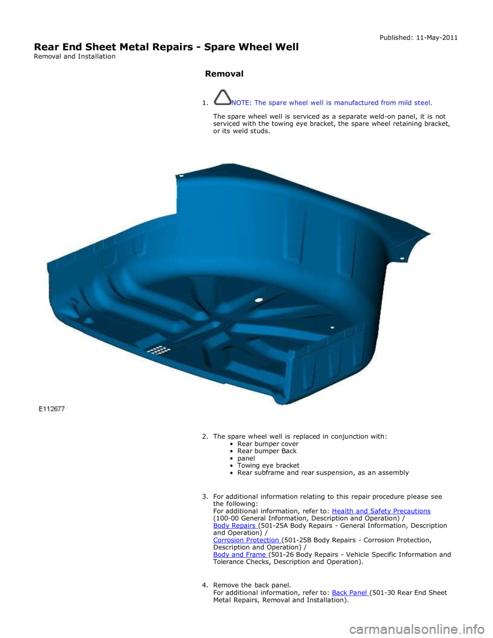
1. NOTE: The spare wheel well is manufactured from mild steel.
The spare wheel well is serviced as a separate weld-on panel, it is not
serviced with the towing eye bracket, the spare wheel retaining bracket,
or its weld studs.
2. The spare wheel well is replaced in conjunction with:
Rear bumper cover
Rear bumper Back
panel
Towing eye bracket
Rear subframe and rear suspension, as an assembly
3. For additional information relating to this repair procedure please see
the following:
For additional information, refer to: Health and Safety Precautions (100-00 General Information, Description and Operation) /
Body Repairs (501-25A Body Repairs - General Information, Description and Operation) /
Corrosion Protection (501-25B Body Repairs - Corrosion Protection, Description and Operation) /
Body and Frame (501-26 Body Repairs - Vehicle Specific Information and Tolerance Checks, Description and Operation).
4. Remove the back panel.
For additional information, refer to: Back Panel (501-30 Rear End Sheet Metal Repairs, Removal and Installation).
Page 2996 of 3039
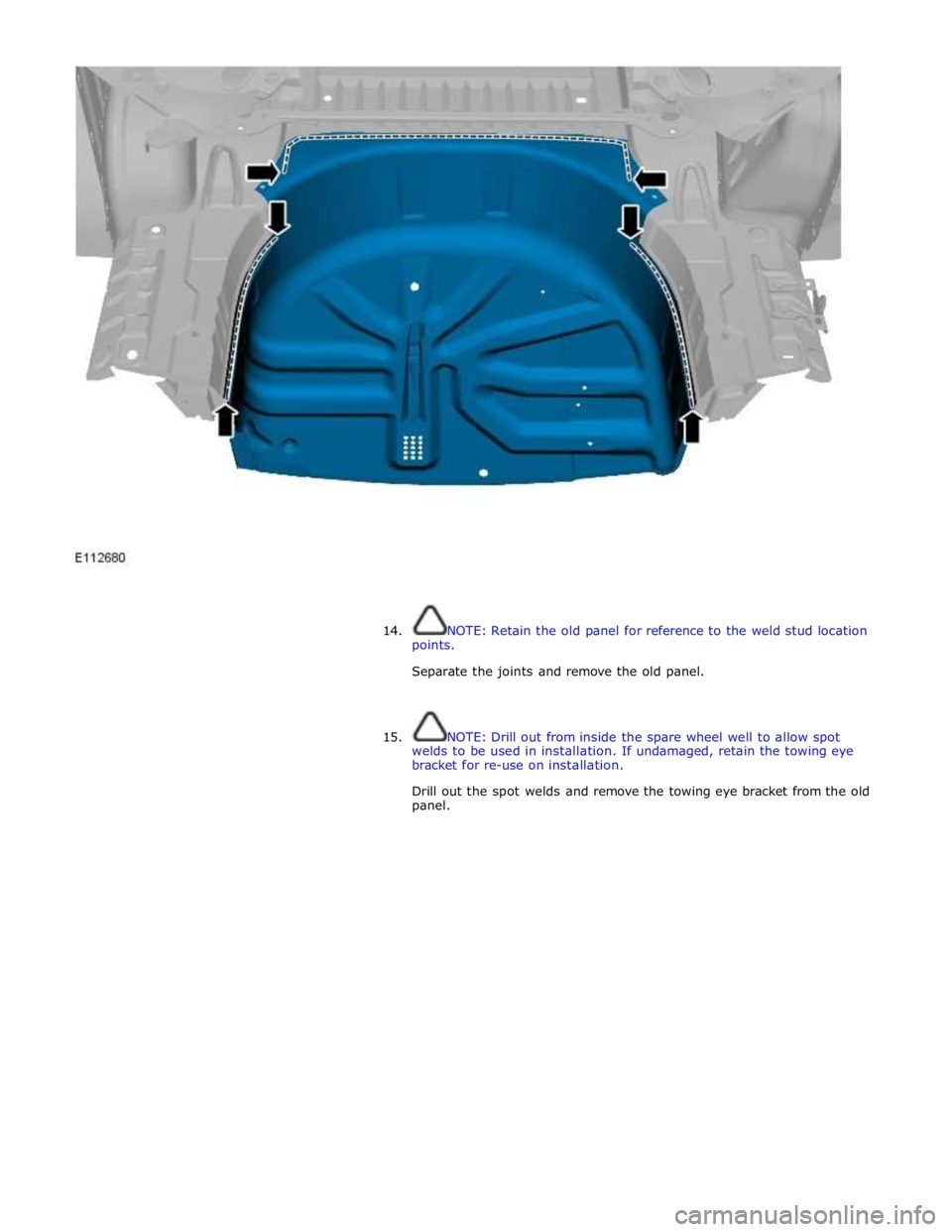
14. NOTE: Retain the old panel for reference to the weld stud location
points.
Separate the joints and remove the old panel.
15. NOTE: Drill out from inside the spare wheel well to allow spot
welds to be used in installation. If undamaged, retain the towing eye
bracket for re-use on installation.
Drill out the spot welds and remove the towing eye bracket from the old
panel.