2010 JAGUAR XFR tow
[x] Cancel search: towPage 1896 of 3039
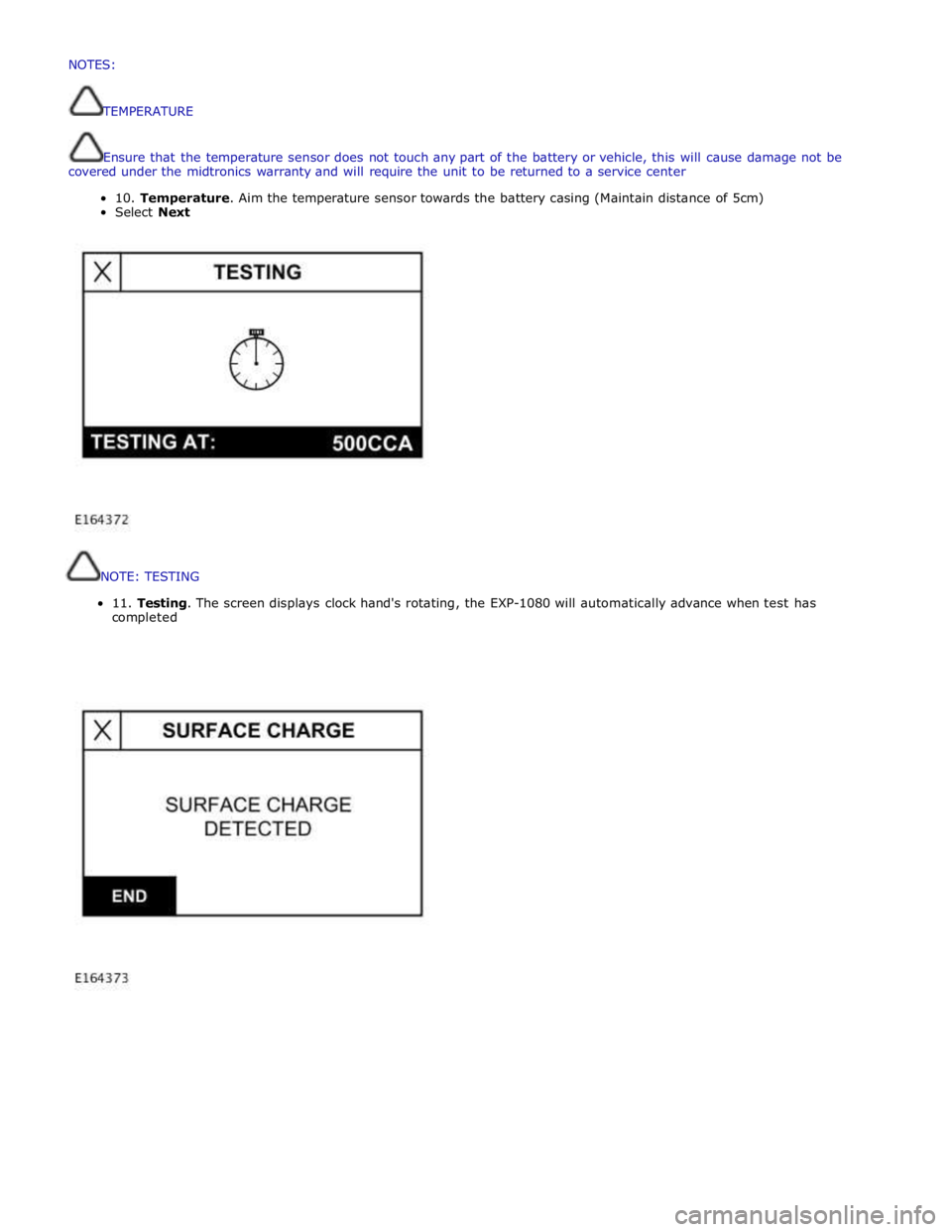
NOTE:
TESTING
11.
Testing.
The
screen
displays
clock
hand's
rotating,
the
EXP-1080
will
automatically
advance
when
test
has
completed
NOTES:
TEMPERATURE
Ensurethatthetemperaturesensordoesnottouchanypartofthebatteryorvehicle,thiswillcausedamagenotbe
coveredunderthemidtronicswarrantyand willrequiretheunittobereturnedtoaservicecenter
10.Temperature.Aimthetemperaturesensortowardsthebatterycasing (Maintaindistanceof5cm)
SelectNext
Page 1958 of 3039
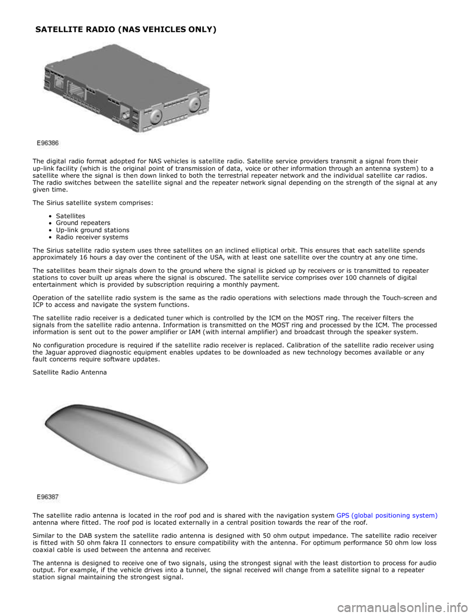
The digital radio format adopted for NAS vehicles is satellite radio. Satellite service providers transmit a signal from their
up-link facility (which is the original point of transmission of data, voice or other information through an antenna system) to a
satellite where the signal is then down linked to both the terrestrial repeater network and the individual satellite car radios.
The radio switches between the satellite signal and the repeater network signal depending on the strength of the signal at any
given time.
The Sirius satellite system comprises:
Satellites
Ground repeaters
Up-link ground stations
Radio receiver systems
The Sirius satellite radio system uses three satellites on an inclined elliptical orbit. This ensures that each satellite spends
approximately 16 hours a day over the continent of the USA, with at least one satellite over the country at any one time.
The satellites beam their signals down to the ground where the signal is picked up by receivers or is transmitted to repeater
stations to cover built up areas where the signal is obscured. The satellite service comprises over 100 channels of digital
entertainment which is provided by subscription requiring a monthly payment.
Operation of the satellite radio system is the same as the radio operations with selections made through the Touch-screen and
ICP to access and navigate the system functions.
The satellite radio receiver is a dedicated tuner which is controlled by the ICM on the MOST ring. The receiver filters the
signals from the satellite radio antenna. Information is transmitted on the MOST ring and processed by the ICM. The processed
information is sent out to the power amplifier or IAM (with internal amplifier) and broadcast through the speaker system.
No configuration procedure is required if the satellite radio receiver is replaced. Calibration of the satellite radio receiver using
the Jaguar approved diagnostic equipment enables updates to be downloaded as new technology becomes available or any
fault concerns require software updates.
Satellite Radio Antenna
The satellite radio antenna is located in the roof pod and is shared with the navigation system GPS (global positioning system)
antenna where fitted. The roof pod is located externally in a central position towards the rear of the roof.
Similar to the DAB system the satellite radio antenna is designed with 50 ohm output impedance. The satellite radio receiver
is fitted with 50 ohm fakra II connectors to ensure compatibility with the antenna. For optimum performance 50 ohm low loss
coaxial cable is used between the antenna and receiver.
The antenna is designed to receive one of two signals, using the strongest signal with the least distortion to process for audio
output. For example, if the vehicle drives into a tunnel, the signal received will change from a satellite signal to a repeater
station signal maintaining the strongest signal. SATELLITE RADIO (NAS VEHICLES ONLY)
Page 1980 of 3039
the roof pod and is shared with the DAB (digital audio broadcasting) band L antenna or satellite radio antenna where fitted.
The roof pod is located externally in a central position towards the rear of the roof.
The GPS antenna is designed with 50 ohm output impedance. The navigation computer is fitted with 50 ohm fakra II connectors to ensure compatibility with the antenna. For optimum performance 50 ohm low loss coaxial cable is used between
the antenna and navigation computer.
It is possible for the GPS antenna to lose the signal from the GPS satellites; In hilly or tree lined areas
Built up areas with tall buildings
In multi storey car parks
In garages
In tunnels
On bridges
During heavy rain or thunderstorms
When the signal is lost the navigation computer will continue to give guidance using memory mapped data from the DVD map until the signal is restored.
TMC/VICS FM Antenna
Data messages for both TMC (traffic message channel) and VICS (vehicle information and communication system) are received
through the FM antennas and diversity antenna module located in the heated rear window.
VICS Beacon Antenna (Japan Only)
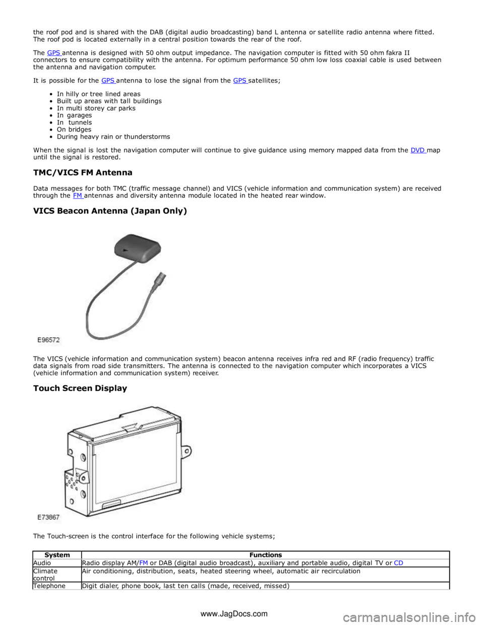
The VICS (vehicle information and communication system) beacon antenna receives infra red and RF (radio frequency) traffic
data signals from road side transmitters. The antenna is connected to the navigation computer which incorporates a VICS
(vehicle information and communication system) receiver.
Touch Screen Display
The Touch-screen is the control interface for the following vehicle systems;
System Functions Audio Radio display AM/FM or DAB (digital audio broadcast), auxiliary and portable audio, digital TV or CD Climate
control Air conditioning, distribution, seats, heated steering wheel, automatic air recirculation Telephone Digit dialer, phone book, last ten calls (made, received, missed) www.JagDocs.com
Page 2087 of 3039

DTC Description Possible Cause Action B10F211 Sunroof Control
Sunroof enable signal circuit -
short to ground Carry out any pinpoint tests associated with this DTC
using the manufacturer approved diagnostic system.
Refer to the electrical circuit diagrams and check sunroof
enable signal circuit for short to ground B10F212 Sunroof Control
Sunroof enable signal circuit -
short to power Refer to the electrical circuit diagrams and check sunroof
enable signal circuit for short to power B10F213 Sunroof Control
Sunroof enable signal circuit -
open circuit Refer to the electrical circuit diagrams and check sunroof
enable signal circuit for open circuit B10F311
Left Front Position
Light
Left front side lamps circuit -
short to ground Carry out any pinpoint tests associated with this DTC
using the manufacturer approved diagnostic system.
Refer to the electrical circuit diagrams and check left
front side lamps circuit for short to ground B10F315
Left Front Position
Light
Left front side lamps circuit -
short to power, open circuit Carry out any pinpoint tests associated with this DTC
using the manufacturer approved diagnostic system.
Refer to the electrical circuit diagrams and check left
front side lamps circuit for short to power, open circuit B10F411
Right Front Position
Light
Right front side lamps circuit -
short to ground Carry out any pinpoint tests associated with this DTC
using the manufacturer approved diagnostic system.
Refer to the electrical circuit diagrams and check right
front side lamps circuit for short to ground B10F415
Right Front Position
Light
Right front side lamps circuit -
short to power, open circuit Carry out any pinpoint tests associated with this DTC
using the manufacturer approved diagnostic system.
Refer to the electrical circuit diagrams and check right
front side lamps circuit for short to power, open circuit B10F812
Accessory socket 'A'
relay
Accessory socket 'A' relay
control circuit - short to power Carry out any pinpoint tests associated with this DTC
using the manufacturer approved diagnostic system.
Refer to the electrical circuit diagrams and check
accessory socket 'A' relay control circuit for short to power B10F814
Accessory socket 'A'
relay
Accessory socket 'A' relay
control circuit - short to ground,
open circuit Refer to the electrical circuit diagrams and check
accessory socket 'A' relay control circuit for short to
ground, open circuit B10F912
Accessory socket 'B'
relay
Front powerpoint, trailer tow
connector, road pricing
connector, sunblind power
supply circuits - short to power Refer to the electrical circuit diagrams and check front
powerpoint, trailer tow connector, road pricing connector,
sunblind power supply circuits for short to power B10F914
Accessory socket 'B'
relay
Front powerpoint, trailer tow
connector, road pricing
connector, sunblind power
supply circuits - short to
ground, open circuit Refer to the electrical circuit diagrams and check front
powerpoint, trailer tow connector, road pricing connector,
sunblind power supply circuits for short to ground, open
circuit B10F993
Accessory socket 'B'
relay
Front powerpoint, trailer tow
connector, road pricing
connector, sunblind power
supply circuits - short to power,
ground, open circuit Carry out any pinpoint tests associated with this DTC
using the manufacturer approved diagnostic system.
Refer to the electrical circuit diagrams and check front
powerpoint, trailer tow connector, road pricing connector,
sunblind power supply circuits for short to power, ground,
open circuit B10FA93
Delayed Power Off
relay
ADRC ECM, roof header console
lamp, glove box lamp , RH/LH
footwell lamps, JAG Sense
glove box module, RH/LH
sunvisor lamps, rear dome
lamps switched power circuits -
short to power, open circuit Carry out any pinpoint tests associated with this DTC
using the manufacturer approved diagnostic system.
Refer to the electrical circuit diagrams and check ADRC
ECM, roof header console lamp, glove box lamp , RH/LH
footwell lamps, JAG Sense glove box module, RH/LH
sunvisor lamps, rear dome lamps switched power circuits
for short to power, open circuit B10FF11 Ignition control
ECM and FPDB ignition control
circuit - short to ground Carry out any pinpoint tests associated with this DTC
using the manufacturer approved diagnostic system.
Refer to the electrical circuit diagrams and check ECM and
FPDB ignition control circuit for short to ground B10FF13 Ignition control
ECM and FPDB ignition control
circuit - open circuit Carry out any pinpoint tests associated with this DTC
using the manufacturer approved diagnostic system.
Refer to the electrical circuit diagrams and check ECM and
FPDB ignition control circuit for open circuit
Page 2095 of 3039

DTC Description Possible Causes Action Write target SID
synchronisation error
following re-programming
Noise/EMC related error B100A63
Fuel Pump
Authorisation
RJB fault
Low speed CAN fault
Instrument cluster fault
Low battery voltage <9V Check power and ground supplies to RJB and instrument cluster.
Check CAN communications between RJB and instrument cluster.
Check battery is in fully charged and serviceable condition, refer
to the battery care manual B102612
Steering Column
Lock
Steering column lock
ground circuit - short to
power Refer to the electrical circuit diagrams and check steering column
lock ground circuit for short to power B108783 LIN Bus "A"
The checksum of the
received LIN frame is
incorrect Check the battery monitoring system and rear parking aid system
for DTCs and refer to relevant DTC Index B108786 LIN Bus "A"
The header of the LIN
message received is
incorrect Carry out any pinpoint test associated with this DTC using the
manufacturer approved diagnostic system. Check the battery
monitoring system and rear parking aid system for DTCs and
refer to relevant DTC Index B108788 LIN Bus "A"
Battery monitoring
system LIN circuit - short
to ground, power Carry out any pinpoint test associated with this DTC using the
manufacturer approved diagnostic system. Refer to the electrical
circuit diagrams and check battery monitoring system LIN circuit
for short to ground, power B108A23 Start Button
Start/Stop switch digital
input signal circuit -
stuck low Carry out any pinpoint test associated with this DTC using the
manufacturer approved diagnostic system. Refer to the electrical
circuit diagrams and check Start/Stop switch digital input signal
circuit for short to ground B10A111 Trailer Tow
Detection
Trailer tow detection
digital input circuit -
short to ground Carry out any pinpoint test associated with this DTC using the
manufacturer approved diagnostic system. Refer to the electrical
circuit diagrams and check trailer tow detection digital input
circuit for short to ground B10AF12 Blower Fan Relay
High Side output not
driven - Diagnosis
feedback indicates output
is short to power Refer to the electrical circuit diagrams and check blower motor
supply circuit for short to power B10AF14 Blower Fan Relay
High Side output not
driven - Diagnosis
feedback indicates output
is short to ground, open
circuit Refer to the electrical circuit diagrams and check blower motor
supply circuit for short to ground, open circuit B10AF93 Blower Fan Relay
High Side output not
driven - Diagnosis
feedback indicates output
is at open load or short
to power Carry out any pinpoint test associated with this DTC using the
manufacturer approved diagnostic system. Refer to the electrical
circuit diagrams and check blower motor supply circuit for short
to power, open circuit B10DD11 Airbag Deployed
Airbag deployed digital
input signal circuit - short
to ground Carry out any pinpoint test associated with this DTC using the
manufacturer approved diagnostic system. Refer to the electrical
circuit diagrams and check airbag deployed digital input signal
circuit for short to ground B10DD15 Airbag Deployed
Airbag deployed digital
input signal circuit - short
to power, open circuit Carry out any pinpoint test associated with this DTC using the
manufacturer approved diagnostic system. Refer to the electrical
circuit diagrams and check airbag deployed digital input signal
circuit for short to power, open circuit B10DD38 Airbag Deployed
Signal frequency incorrect Check the RCM for related DTCs and refer to the relevant DTC
Index B10DE11
Low Fuel Warning
Switch
Diesel run-dry switch
analogue input circuit -
short to ground Carry out any pinpoint test associated with this DTC using the
manufacturer approved diagnostic system. Refer to the electrical
circuit diagrams and check diesel run-dry switch analogue input
circuit for short to ground www.JagDocs.com
Page 2121 of 3039

Anti-Theft - Active - Anti-Theft - Active - Overview
Description and Operation
Overview Published: 11-May-2011
The active anti-theft system is available with three different levels of vehicle protection depending on market specification:
Hinged panel sensing
Hinged panel and intrusion sensing
Hinged panel, intrusion and inclination sensing.
The CJB (central junction box) automatically arms and disarms the active anti-theft system when it functions the central
locking system.
Refer to: Handles, Locks, Latches and Entry Systems (501-14 Handles, Locks, Latches and Entry Systems, Description and Operation).
Depending on market specification two modes of protection are used: perimeter mode and volumetric mode.
Perimeter mode
Perimeter mode, monitors the security of the hinged panels, which include:
all doors,
luggage compartment lid, and
engine compartment lid.
When perimeter mode is active, the CJB monitors the panel ajar switches in the latch mechanisms of the hinged panels.
Volumetric mode
In volumetric mode the CJB monitors the interior of the vehicle for movement using an ultrasonic sound wave sensor.
If the battery backed sounder incorporates an inclination sensor the vehicle will also be monitored for unauthorised tilting; for
example towing or jacking.
Page 2292 of 3039

Rear View Mirrors - Rear View Mirrors - Overview
Description and Operation
Overview
The exterior mirrors incorporate the following:
Blind spot monitoring indicator
Auto dimming function
Turn signal indicators
Approach lamps
Exterior temperature sensor
Heated mirror function
Reverse dipping function Published: 11-May-2011
Movement of the door mirrors is controlled from a switch pack located on the drivers door. The switch pack contains 2
non-latching mirror select buttons labeled 'L' and 'R' and a 4-way mirror movement switch. Door mirror movement commands
are transmitted to the driver's door module over the LIN (local interconnect network) bus. The drivers door module transmits
any mirror movement commands to the passenger door module over the medium speed CAN (controller area network) bus.
Movement of the door mirrors is carried out by the respective door module. The door modules provide supply and ground paths
to the mirror motors and monitor mirror position via potentiometers located in the mirror housings.
Both exterior door mirrors and the interior mirror feature an auto dimming function. The interior rear view mirror contains one
forward and one reward facing light sensor. The light sensors control the auto dimming feature of the interior mirror to reduce
glare from the headlights of following vehicles.
When auto-dimming of the interior mirror is required, a supply is provided by the interior mirror to both door mirrors to initiate
the door mirror auto-dimming sequence.
Blind spot monitoring function alerts the driver to a vehicle located in the vehicle blind spot. A warning indicator is located in
each exterior mirror towards the outer edge.
Refer to: Blindspot Monitoring System (413-09 Warning Devices, Description and Operation).
Page 2354 of 3039
Seating - Seat Smoothing
General Procedures Published: 01-May-2014
WARNINGS: Check
Make sure that the steamer is in the OFF position before connecting or disconnecting from the electrical outlet.
Do not use another high wattage device on the same electrical circuit.
If the use of an extension cord is absolutely necessary, the cord must be rated at a minimum of 10 amps.
To avoid the risk of electrical shock, check the condition of the power cord and the steamer before use.
Make sure that the steamer is disconnected from the electrical outlet before filling or emptying the water reservoir.
The steamer must only be used and placed on its stand on a stable surface.
To prevent injury such as burns, take care whilst using the steamer. Avoid coming into contact with the hot surface of the
steamer and do not direct steam toward any persons.
The steamer must ALWAYS be switched off when not in use or left unattended.
Do not allow the power cord to come into contact with the hot surface of the steamer.
CAUTIONS:
Protect the surrounding paintwork to avoid damage.
Protect the paintwork during this operation.
Do not use any additives in the steamer. Damage to the steamer or the seat cover can result if used.
NOTE: Some variation in the illustrations may occur, but the essential information is always correct.
1. CAUTIONS:
Steam the leather cushions evenly and progressively. Do not use
excessive force.
Take care not to damage the leather whilst steaming into the
corners.
Do not hold the steamer in one place for longer than 10 seconds,
as this will burn the leather and damage the covers. www.JagDocs.com