2010 JAGUAR XFR tow
[x] Cancel search: towPage 302 of 3039

and drive half shaft failure, which could cause serious personal injury and extensive vehicle damage. Failure to follow these
instructions may result in personal injury.
CAUTION: The suspension should not be allowed to hang free. When the CV joint is run at a very high angle, extra
vibration as well as damage to the seals and joints can occur.
The rear suspension lower arm should be supported as far outboard as possible. To bring the vehicle to its correct ride height,
the full weight of the vehicle should be supported in the rear by floor jacks. REFER to: (100-02 Jacking and Lifting)
Jacking (Description and Operation), Lifting (Description and Operation).
1. Raise and support the vehicle. REFER to: (100-02 Jacking and Lifting)
Jacking (Description and Operation), Lifting (Description and Operation).
2. Explore the speed range of interest using the Road Test Quick Checks as previously described.
3. Carry out a coast down in neutral. If the vehicle is free of vibration when operating at a steady indicated speed and
behaves very differently in drive and coast, a transmission concern is likely.
Note, however, that a test on the lift may produce different vibrations and noises than a road test because of the effect of the
lift. It is not unusual to find vibrations on the lift that were not found in the road test. If the condition found on the road can
be duplicated on the lift, carrying out experiments on the lift may save a great deal of time.
Exhaust Neutralization Procedure
1. Raise vehicle on lift and slacken all exhaust fixings.
2. With all fixings loose, neutralize the exhaust system.
3. Tighten all fixings to correct torque, starting at the rear-most point working towards the front of the vehicle.
Symptom Chart
Symptom Possible Cause Action High-speed shake
Wheel end vibration
Engine/transmission
Driveline GO to Pinpoint Test A. Tip-in moan
Air cleaner
Power steering
Powertrain
Engine mounts
Exhaust system GO to Pinpoint Test B. Idle boom/shake/vibration, or shudder
Cable(s)/hoses(s)
Intake air distribution and filtering system
Engine mounts
Exhaust system
Belt/pulleys GO to Pinpoint Test C. Wheel end vibration analysis
Suspension/rear drive halfshaft and CV joints
Tires/wheels
Wheel bearings
CV joint boots GO to Pinpoint Test D. Non-axle noise
Trim/mouldings
A/C system
Accessories GO to Pinpoint Test E. Pinpoint Tests
NOTE: These Pinpoint Tests are designed to take the technician through a step-by-step diagnosis procedure to determine
the cause of a condition. It may not always be necessary to follow the chart to its conclusion. Carry out only the Pinpoint Test
steps necessary to correct the condition. Then check operation of the system to make sure the condition is corrected.
After verifying that the condition has been corrected, make sure all components removed have been installed.
PINPOINT TEST A : HIGH-SPEED SHAKE TEST DETAILS/RESULTS/ACTIONS www.JagDocs.com
Page 470 of 3039

Installation
1. CAUTIONS:
Make sure that the seal is correctly located.
Make sure that new components are installed.
Install the washer and seal, making sure the valve remains
pressed fully onto its seat.
2. WARNINGS:
Make sure that any corrosion or dirt is removed from the
mating surfaces.
Make sure that a new tire valve, valve core, seal, washer,
cap and retaining nut is installed.
CAUTIONS:
Use lint free cloth.
Only use moderate force when installing the sensor.
NOTE: Only tighten the nut finger tight at this stage.
Install the tire low pressure sensor and support the
sensor body in position.
Support the back of the valve stem in order to prevent
rotation to the tire low pressure sensor body.
Gently push the nut towards the center of the wheel.
Tighten the nut.
Torque: 8 Nm
3. Install the tire and balance the wheel.
4. Refer to: Wheel and Tire (204-04 Wheels and Tires, Removal and Installation).
5. WARNING: Make sure to support the vehicle with axle stands.
Lower the vehicle.
Page 694 of 3039

7 Brake fluid level switch 8 LH rear wheel speed sensor 9 RH rear wheel speed sensor 10 RJB (rear junction box) 11 High mounted stop lamp 12 LH stop lamp 13 RH stop lamp 14 Diagnostic socket 15 TCM (transmission control module) 16 Electronic parking brake module 17 ECM (engine control module) 18 Instrument cluster 19 ABS (anti-lock brake system) module 20 JaguarDrive selector module 21 Adaptive damping control module 22 Adaptive speed control module 23 Yaw rate and lateral acceleration sensor 24 Roof opening panel motor/module 25 Brake booster vacuum sensor (3.0L vehicles only) 26 Steering angle sensor
Anti-Lock Brake System System Operation
ABS controls the speed of all road wheels to ensure optimum wheel slip when braking at the adhesion limit. The wheels are prevented from locking to retain effective steering control of the vehicle.
The brake pressures are modulated separately for each wheel. Rear brake pressures are controlled to maintain rear stability on
split friction surfaces.
Dynamic Stability Control
DSC (dynamic stability control) uses brakes and powertrain torque control to assist in maintaining the yaw stability of the
vehicle. While the ignition is energized the DSC function is permanently enabled, unless selected off using the DSC switch.
DSC enhances driving safety in abrupt maneuvers and in under-steer or over-steer situations that may occur in a bend. The
ABS module monitors the yaw rate and lateral acceleration of the vehicle, steering input and individual wheel speeds, then selectively applies individual brakes and signals for powertrain torque adjustments to reduce under-steer or over-steer
conditions.
In general:
In an under-steer situation the inner wheels are braked to counteract the yaw movement towards the outer edge of the
bend.
In an over-steer situation the outer wheels are braked to prevent the rear end of the vehicle from pushing towards the
outer edge of the bend.
The ABS module monitors the tracking stability of the vehicle using inputs from the wheel speed sensors, the steering angle sensor, and the yaw rate and lateral acceleration sensor. The tracking stability is compared with stored target data. Whenever
the tracking stability deviates from the target data, the ABS module intervenes by applying the appropriate control strategy. The following interactions occur in an intervention situation:
High speed CAN signal to the ECM, to reduce engine torque. Application of braking to the appropriate corner of the vehicle.
Trac DSC
TracDSC is an alternative setting of DSC with reduced system interventions. With TracDSC engaged, traction may be somewhat
increased, although stability may be reduced compared to normal DSC. TracDSC is intended for use only on dry tarmac, by
suitably experienced drivers and should not be selected for other surfaces or by drivers with insufficient skill and training to
operate the vehicle safely with the TracDSC function engaged.
The less restrictive TracDSC setting may be preferred, for example, by expert drivers engaged in high performance driving on
dry Tarmac surfaces such as tracks and circuits.
Switching between DSC and Trac DSC:
Page 814 of 3039
engine oil).
Oil Consumption Test
The amount of oil an engine uses will vary with the way the vehicle is driven in addition to normal engine-to-engine variation.
This is especially true during the first 16,100 km (10,000 miles) when a new engine is being broken in or until certain internal
components become conditioned. Vehicles used in heavy-duty operation may use more oil. The following are examples of
heavy-duty operation:
Trailer towing applications
Severe loading applications
Sustained high speed operation
Engines need oil to lubricate the following internal components:
Cylinder block cylinder walls
Pistons and piston rings
Intake and exhaust valve stems
Intake and exhaust valve guides
All internal engine components
When the pistons move downward, a thin film of oil is left on the cylinder walls. As the vehicle is operated, some oil is also
drawn into the combustion chambers past the intake and exhaust valve stem seals and burned.
The following are examples of conditions that can affect oil consumption rates:
Engine size
Operator driving habits
Ambient temperatures
Quality and viscosity of oil
Engine is being run in an overfilled condition (check the oil level at least five minutes after a hot shutdown with the
vehicle parked on a level surface. The oil level should not be above the top of the cross-hatched area and the letter "F"
in FULL).
Operation under varying conditions can frequently be misleading. A vehicle that has been run for several thousand miles on
short trips or in below-freezing ambient temperatures may have consumed a "normal" amount of oil. However, when checking
the engine oil level, it may measure up to the full mark on the oil level indicator due to dilution (condensation and fuel) in the
engine crankcase. The vehicle then might be driven at high speeds on the highway where the condensation and fuel boil off.
The next time the engine oil is checked it may appear that a liter of oil was used in about 160 km (100 miles). Oil
consumption rate is about one liter per 2,400 km (1,500 miles).
Make sure the selected engine oil meets Jaguar specification and the recommended API performance category "SG" and SAE
viscosity grade as shown in the vehicle Owner's Guide. It is also important that the engine oil is changed at the intervals
specified for the typical operating conditions.
The following diagnostic procedure is used to determine the source of excessive oil consumption.
NOTE: Oil use is normally greater during the first 16,100 km (10,000 miles) of service. As mileage increases, oil use
decreases. High speed driving, towing, high ambient temperature and other factors may result in greater oil use.
1. Define excessive consumption, such as the number of miles driven per liter of oil used. Also determine customers
driving habits, such as sustained high speed operation, towing, extended idle and other considerations.
2. Verify that the engine has no external oil leaks as described under Engine Oil Leaks in this section.
3. Carry out an oil consumption test:
Run the engine to normal operating temperature. Switch engine OFF and allow oil to drain back for at least five
minutes .
With vehicle parked on level surface, check the engine oil level.
If required, add engine oil to set level exactly to the FULL mark.
Record the vehicle mileage.
Instruct the customer to return for a level check after driving the vehicle as usual for 1,610 km (1000 miles).
Check the oil level under the same conditions and at the same location as the initial check.
NOTE: If the oil consumption rate is unacceptable go to Step 4.
4. Check the Positive Crankcase Ventilation (PCV) system. Make sure the system is not plugged.
5. Check for plugged oil drain-back holes in the cylinder head and cylinder block.
6. If the condition still exists after carrying out the above tests go to step 9.
7. Carry out a cylinder compression test. Refer to the Compression Test procedure in this section. This can help determine
the source of oil consumption such as valves, piston rings or other areas.
8. Check valve guides for excessive guide clearance. Install new valve stem seals after verifying valve guide clearance.
9. Worn or damaged internal engine components can cause excessive oil consumption. Small deposits of oil on the tips of
the spark plugs can be a clue to internal oil consumption.
Page 1586 of 3039
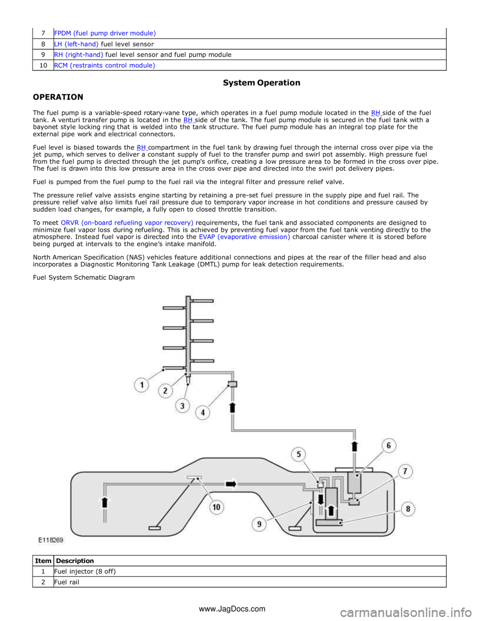
8 LH (left-hand) fuel level sensor 9 RH (right-hand) fuel level sensor and fuel pump module 10 RCM (restraints control module)
OPERATION System Operation
The fuel pump is a variable-speed rotary-vane type, which operates in a fuel pump module located in the RH side of the fuel tank. A venturi transfer pump is located in the RH side of the tank. The fuel pump module is secured in the fuel tank with a bayonet style locking ring that is welded into the tank structure. The fuel pump module has an integral top plate for the
external pipe work and electrical connectors.
Fuel level is biased towards the RH compartment in the fuel tank by drawing fuel through the internal cross over pipe via the jet pump, which serves to deliver a constant supply of fuel to the transfer pump and swirl pot assembly. High pressure fuel
from the fuel pump is directed through the jet pump's orifice, creating a low pressure area to be formed in the cross over pipe.
The fuel is drawn into this low pressure area in the cross over pipe and directed into the swirl pot delivery pipes.
Fuel is pumped from the fuel pump to the fuel rail via the integral filter and pressure relief valve.
The pressure relief valve assists engine starting by retaining a pre-set fuel pressure in the supply pipe and fuel rail. The
pressure relief valve also limits fuel rail pressure due to temporary vapor increase in hot conditions and pressure caused by
sudden load changes, for example, a fully open to closed throttle transition.
To meet ORVR (on-board refueling vapor recovery) requirements, the fuel tank and associated components are designed to
minimize fuel vapor loss during refueling. This is achieved by preventing fuel vapor from the fuel tank venting directly to the
atmosphere. Instead fuel vapor is directed into the EVAP (evaporative emission) charcoal canister where it is stored before
being purged at intervals to the engine’s intake manifold.
North American Specification (NAS) vehicles feature additional connections and pipes at the rear of the filler head and also
incorporates a Diagnostic Monitoring Tank Leakage (DMTL) pump for leak detection requirements.
Fuel System Schematic Diagram
Item Description 1 Fuel injector (8 off) 2 Fuel rail www.JagDocs.com
Page 1834 of 3039
Blind Spot Monitoring System Operation
The purpose of the blind spot monitoring system is to detect an object moving with a positive velocity relative to the radar
module, on either side of the vehicle, at a distance of up to 2.5 meters laterally and in an area from the door mirror up to 7.0
meters behind the module. These criteria identify an overtaking vehicle within the blind-spot area and within a typical
carriageway lane width, while eliminating other objects that are not relevant, either because of their position, they are
stationary, traveling in the opposite direction, or being overtaken. A vehicle is classed as a heavy goods vehicle, car or
motorcycle. A motorcycle is defined as a minimum size of 2.0m long, 0.8m wide (widest point) and 1.1m high. The system is
not affected by the mass of the overtaking vehicle providing all identification criteria, including relative velocity of (16km/h -
10mph) or above, is met.
The system emits radar pulses and analyses the reflections, identifying anything that moves into the blind spot zone. Having
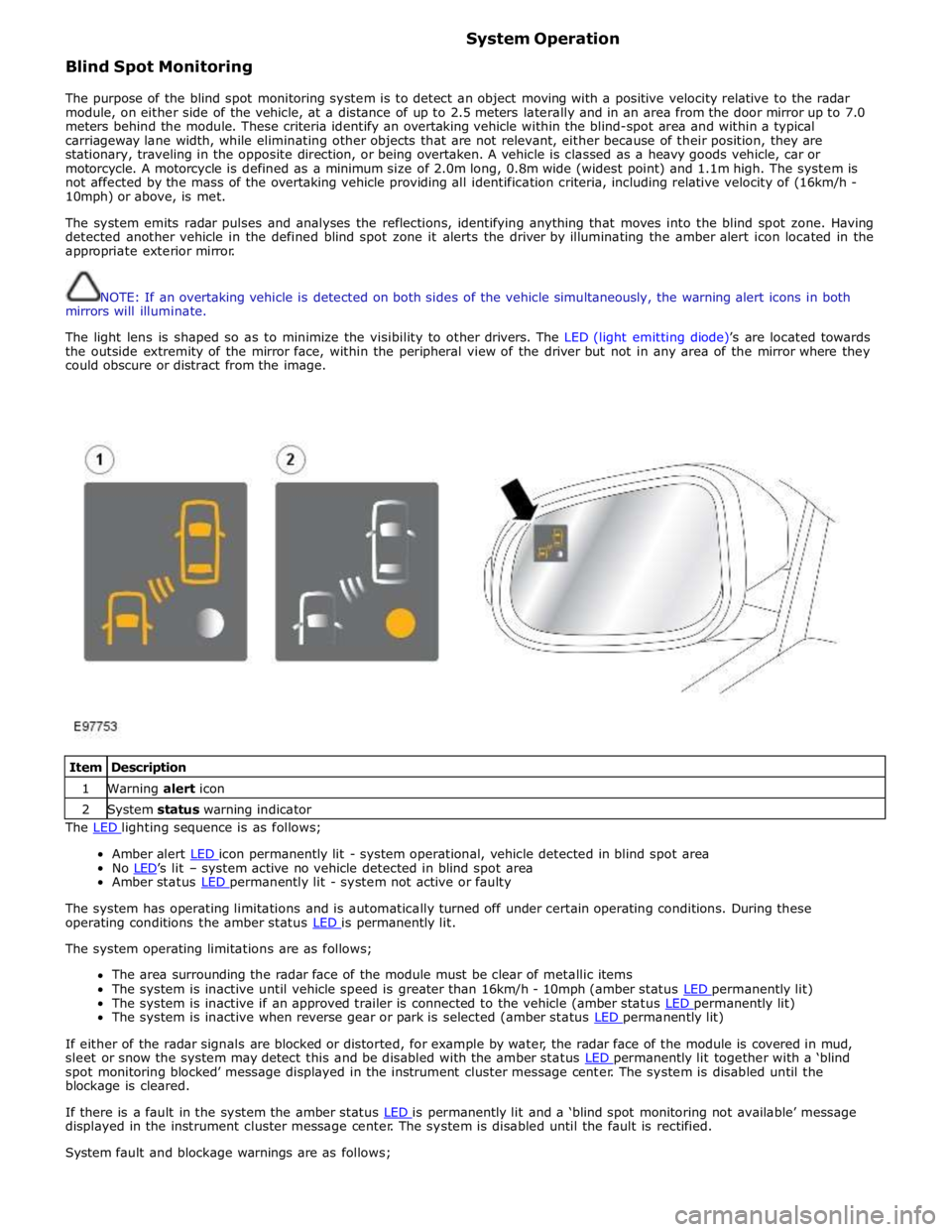
detected another vehicle in the defined blind spot zone it alerts the driver by illuminating the amber alert icon located in the
appropriate exterior mirror.
NOTE: If an overtaking vehicle is detected on both sides of the vehicle simultaneously, the warning alert icons in both
mirrors will illuminate.
The light lens is shaped so as to minimize the visibility to other drivers. The LED (light emitting diode)’s are located towards
the outside extremity of the mirror face, within the peripheral view of the driver but not in any area of the mirror where they
could obscure or distract from the image.
Item Description 1 Warning alert icon 2 System status warning indicator The LED lighting sequence is as follows;
Amber alert LED icon permanently lit - system operational, vehicle detected in blind spot area No LED’s lit – system active no vehicle detected in blind spot area Amber status LED permanently lit - system not active or faulty
The system has operating limitations and is automatically turned off under certain operating conditions. During these
operating conditions the amber status LED is permanently lit. The system operating limitations are as follows;
The area surrounding the radar face of the module must be clear of metallic items
The system is inactive until vehicle speed is greater than 16km/h - 10mph (amber status LED permanently lit) The system is inactive if an approved trailer is connected to the vehicle (amber status LED permanently lit) The system is inactive when reverse gear or park is selected (amber status LED permanently lit)
If either of the radar signals are blocked or distorted, for example by water, the radar face of the module is covered in mud,
sleet or snow the system may detect this and be disabled with the amber status LED permanently lit together with a ‘blind spot monitoring blocked’ message displayed in the instrument cluster message center. The system is disabled until the
blockage is cleared.
If there is a fault in the system the amber status LED is permanently lit and a ‘blind spot monitoring not available’ message displayed in the instrument cluster message center. The system is disabled until the fault is rectified.
System fault and blockage warnings are as follows;
Page 1851 of 3039
Mechanical Electrical Parking aid control module
Parking aid sounder
Audio system
4. If an obvious cause for an observed or reported concern is found, correct the cause (if possible) before proceeding to
the next step
5. If the cause is not visually evident, check for diagnostic trouble codes (DTCs) and refer to the DTC index
Symptom Chart
CAUTION: Do not apply any grease based products to any parking aid system connector or pins
NOTES:
Please note if this diagnosis is being carried out on a vehicle without a hard wired parking aid speaker, ensure the in car
infotainment system is fully functional and configured correctly
Parking aid sensors that are painted incorrectly and not to the manufacturer standards, will not be considered in any
warranty claim
Symptom Possible Causes Action
NOTE:
Permanent/Intermittent fault
Parking aid system not
functioning correctly. (No
DTCs displayed)
Front or rear parking aid
sensors dirty
Front or rear parking aid
sensor position incorrect
Front or rear parking aid
sensor incorrectly installed
Front or rear parking aid
sensor coupling rings not
installed/incorrectly installed
Parking aid control module or
parking aid sensor connector
not fully latched
Parking aid sensors painted
without being removed from
the bumper assembly or not
painted to the manufacturer
specification
Clean front or rear parking aid sensors
Check the front or parking aid rear sensor position
Check the front or rear parking aid sensor are
correctly installed
Check front or rear parking aid sensor coupling
rings are installed/installed correctly
Ensure all parking aid system connectors are
correctly latched
Remove parking aid sensor and ensure correctly
painted parking aid sensor is installed
- Parking aid sensors that are painted
incorrectly and not to the manufacturer
standards, will not be considered in any
warranty claim
NOTE:
Permanent/Intermittent fault
Parking aid system not
functioning correctly. (No
DTCs displayed). System
characteristics or
environmental effects
Parking aid sensors incorrectly
mounted
Incorrect vehicle ride height
Dirty parking aid sensor face.
Ice/snow covered sensor.
Debris trapped between
parking aid sensor and
parking aid sensor body.
Heavy rain or water splash
from the ground
Non standard, bumper,
exhausts/tailpipes, tow bar or
external spare wheel
mounting
Area around vehicle is not
clear of obstacles such as
channels, gutters or other
items on the ground
Exhaust gas and warm air
clouds creating ghost echoes
Vehicle not on level ground or
next to a gradient
Parking aid sensors painted
without being removed from
the bumper assembly or not
painted to the manufacturer
specification
Ensure the sensors are a tight fit in the holder and
locked. Ensure the sensors are central in the holder
and bumper and at the correct angle
Ensure vehicle ride height is within the specified
limits. Rectify as required
Clean the sensor face as required. Defrost the
sensor and dry as required. Clear any debris from
the sensor and holder as required. Water flowing
over the sensor is a system limitation. (no action
required)
Check for non standard, bumper, exhausts/tailpipe,
tow bar or external spare wheel mounting that may
be being detected by the parking aid system.
Rectify as required
Ensure the area around the vehicle is clear of any
obstacles, move the vehicle to a suitable area
before continuing diagnosis
Ensure no exhaust gas or warm area clouds are in
the area around the parking aid sensor detection
range
Ensure the vehicle is on level ground and clear of
any ramps, potholes or speed bumps, move the
vehicle to a suitable area before continuing
diagnosis
Remove parking aid sensor and ensure correctly
painted parking aid sensor is installed
- Parking aid sensors that are painted
incorrectly and not to the manufacturer
standards, will not be considered in any
warranty claim
Page 1854 of 3039
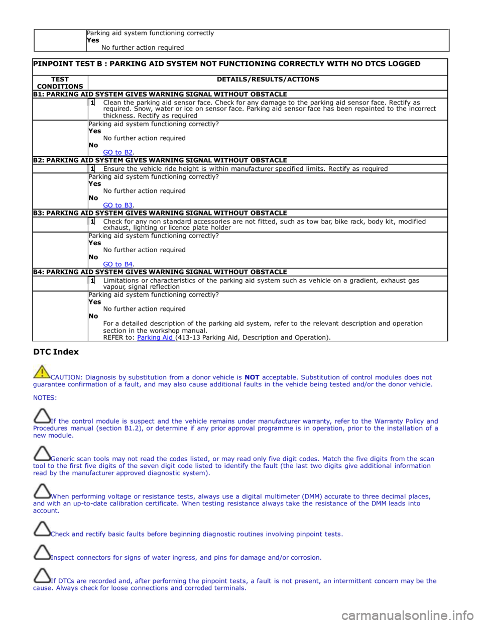
PINPOINT TEST B : PARKING AID SYSTEM NOT FUNCTIONING CORRECTLY WITH NO DTCS LOGGED TEST
CONDITIONS DETAILS/RESULTS/ACTIONS B1: PARKING AID SYSTEM GIVES WARNING SIGNAL WITHOUT OBSTACLE 1 Clean the parking aid sensor face. Check for any damage to the parking aid sensor face. Rectify as required. Snow, water or ice on sensor face. Parking aid sensor face has been repainted to the incorrect
thickness. Rectify as required Parking aid system functioning correctly? Yes
No further action required
No
GO to B2. B2: PARKING AID SYSTEM GIVES WARNING SIGNAL WITHOUT OBSTACLE 1 Ensure the vehicle ride height is within manufacturer specified limits. Rectify as required Parking aid system functioning correctly? Yes
No further action required
No
GO to B3. B3: PARKING AID SYSTEM GIVES WARNING SIGNAL WITHOUT OBSTACLE 1 Check for any non standard accessories are not fitted, such as tow bar, bike rack, body kit, modified exhaust, lighting or licence plate holder Parking aid system functioning correctly? Yes
No further action required
No
GO to B4. B4: PARKING AID SYSTEM GIVES WARNING SIGNAL WITHOUT OBSTACLE 1 Limitations or characteristics of the parking aid system such as vehicle on a gradient, exhaust gas vapour, signal reflection Parking aid system functioning correctly? Yes
No further action required
No
For a detailed description of the parking aid system, refer to the relevant description and operation
section in the workshop manual.
REFER to: Parking Aid (413-13 Parking Aid, Description and Operation). DTC Index
CAUTION: Diagnosis by substitution from a donor vehicle is NOT acceptable. Substitution of control modules does not
guarantee confirmation of a fault, and may also cause additional faults in the vehicle being tested and/or the donor vehicle.
NOTES:
If the control module is suspect and the vehicle remains under manufacturer warranty, refer to the Warranty Policy and
Procedures manual (section B1.2), or determine if any prior approval programme is in operation, prior to the installation of a
new module.
Generic scan tools may not read the codes listed, or may read only five digit codes. Match the five digits from the scan
tool to the first five digits of the seven digit code listed to identify the fault (the last two digits give additional information
read by the manufacturer approved diagnostic system).
When performing voltage or resistance tests, always use a digital multimeter (DMM) accurate to three decimal places,
and with an up-to-date calibration certificate. When testing resistance always take the resistance of the DMM leads into
account.
Check and rectify basic faults before beginning diagnostic routines involving pinpoint tests.
Inspect connectors for signs of water ingress, and pins for damage and/or corrosion.
If DTCs are recorded and, after performing the pinpoint tests, a fault is not present, an intermittent concern may be the
cause. Always check for loose connections and corroded terminals. Parking aid system functioning correctly
Yes
No further action required