Page 1715 of 3039

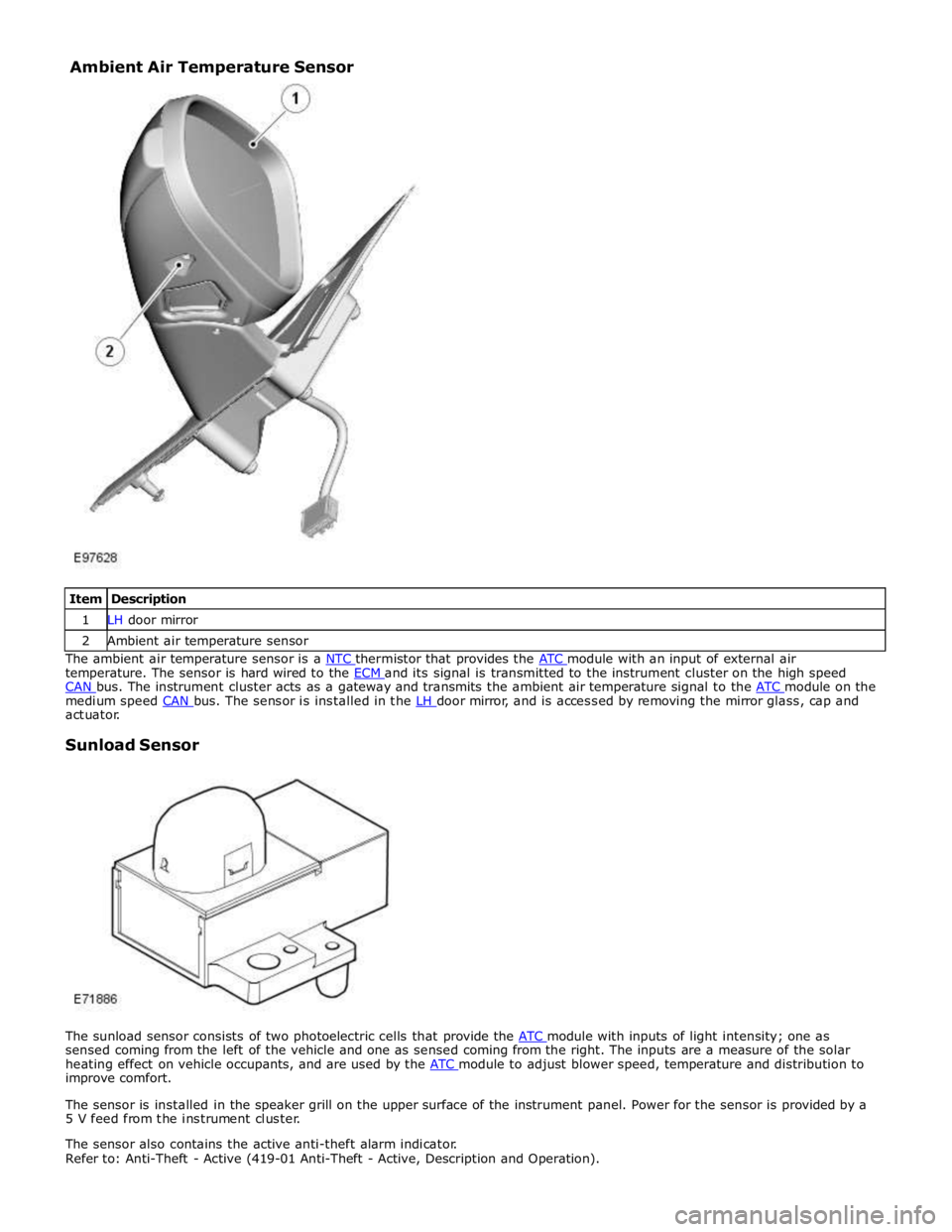
1 LH door mirror 2 Ambient air temperature sensor The ambient air temperature sensor is a NTC thermistor that provides the ATC module with an input of external air temperature. The sensor is hard wired to the ECM and its signal is transmitted to the instrument cluster on the high speed CAN bus. The instrument cluster acts as a gateway and transmits the ambient air temperature signal to the ATC module on the medium speed CAN bus. The sensor is installed in the LH door mirror, and is accessed by removing the mirror glass, cap and actuator.
Sunload Sensor
The sunload sensor consists of two photoelectric cells that provide the ATC module with inputs of light intensity; one as sensed coming from the left of the vehicle and one as sensed coming from the right. The inputs are a measure of the solar
heating effect on vehicle occupants, and are used by the ATC module to adjust blower speed, temperature and distribution to improve comfort.
The sensor is installed in the speaker grill on the upper surface of the instrument panel. Power for the sensor is provided by a
5 V feed from the instrument cluster.
The sensor also contains the active anti-theft alarm indicator.
Refer to: Anti-Theft - Active (419-01 Anti-Theft - Active, Description and Operation). Ambient Air Temperature Sensor
Page 1716 of 3039
as nitrous oxides, sulphur oxides and carbon monoxide. The sensor is attached to the center of the upper front crossmember.
The pollution sensor is powered by an ignition controlled voltage feed from the CJB and provides the ATC module with separate signals of hydrocarbon and oxidized gas levels. With a pollution sensor fitted, the ATC module can control the air inlet source to reduce the amount of contaminants entering the passenger compartment. This function is fully automatic, but can be
overridden by manual selection of the air source using the recirculation switch on the integrated control panel.
If there is a fault with the sensor, the ATC module disables automatic operation of the recirculation door.
Page 1717 of 3039
Climate Control - Ambient Air Temperature Sensor
Removal and Installation
Removal
NOTE: Removal steps in this procedure may contain installation details. Published: 11-May-2011
1. Refer to: Exterior Mirror Cover (501-09 Rear View Mirrors, Removal and Installation).
2.
3. www.JagDocs.com
Page 1736 of 3039
Installation
9.
10.
NOTE: Some variation in the illustrations may occur,
but the essential information is always correct.
WARNING: Only use moderate force when installing
the sensor.
CAUTIONS:
Make sure the evaporator temperature sensor harness
does not become trapped.
Make sure that the sensor is correctly installed.
NOTE: Some variation in the illustrations may occur,
but the essential information is always correct.
1. To install, reverse the removal procedure.
Page 1750 of 3039
Climate Control - In-Vehicle Temperature Sensor
Removal and Installation
Removal
NOTE: Removal steps in this procedure may contain installation details. Published: 11-May-2011
1. Refer to: Glove Compartment (501-12 Instrument Panel and Console, Removal and Installation).
2.
Installation
1. To install, reverse the removal procedure.
Page 1758 of 3039
Climate Control - Sunload Sensor
Removal and Installation
Removal
NOTE: Removal steps in this procedure may contain installation details. Published: 11-May-2011
1. Refer to: Battery Disconnect and Connect (414-01 Battery, Mounting and Cables, General Procedures).
2. CAUTIONS:
Protect the surrounding trim to avoid damage.
Make sure that the clips are correctly located.
3.
4. CAUTION: Make sure that the component is correctly
located on the locating dowels.
Torque: 2 Nm
Page 1767 of 3039

7 ECT (engine coolant temperature) sensor 8 Ambient temperature sensor 9 Electric booster heater 10 Face/Feet distribution stepper motor 11 RH (right-hand) temperature blend stepper motor 12 LH (left-hand) temperature blend stepper motor 13 Windshield (defrost) distribution stepper motor 14 ATC (automatic temperature control) module 15 150 A megafuse
General System Operation
Operation of the electric booster heater is controlled by the ATC module, which communicates with the micro-controller in the booster heater using the LIN bus. The temperature requested by the ATC module is based on:
The ambient air temperature.
The engine coolant temperature.
The temperatures selected on the integrated control panel.
The blower must be running for the electric booster heater to operate.
If electrical load management is in force, electric booster heater performance is reduced. For additional information, refer to:
Electronic Engine Controls (303-14A, Description and Operation),
Electronic Engine Controls (303-14B Electronic Engine Controls - V6 3.0L Petrol, Description and Operation), Electronic Engine Controls (303-14C, Description and Operation).
Electric Booster Heater Component Description
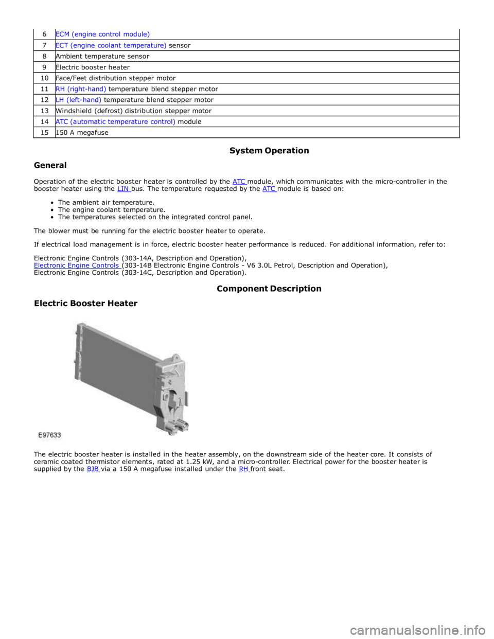
The electric booster heater is installed in the heater assembly, on the downstream side of the heater core. It consists of
ceramic coated thermistor elements, rated at 1.25 kW, and a micro-controller. Electrical power for the booster heater is
supplied by the BJB via a 150 A megafuse installed under the RH front seat.
Page 1783 of 3039
Published: 11-May-2011
Instrument Cluster - Instrument Cluster - System Operation and Component Description
Description and Operation
Control Diagram
NOTE: A = Hardwired; D = High speed CAN (controller area network) bus; N = Medium speed CAN bus; O = LIN (local interconnect network) bus
Item Description 1 Battery 2 BJB (battery junction box) 3 EJB (engine junction box) 4 CJB (central junction box) 5 Sun load sensor (alarm LED (light emitting diode))