2010 JAGUAR XFR wheel
[x] Cancel search: wheelPage 1800 of 3039

DTC Description Possible Cause Action B100D96
Column Lock
Authorisation -
Component
internal failure
Battery voltage at electric
steering column lock control
module too low
Torque load on steering
column
CAN fault
Electric steering column lock
control module - Internal
failure
Clear DTC, repeatedly lock and unlock car using the
key fob and retest
If fault persists, check that the vehicle battery supply
voltage is between 9-16 volts. Rectify as required
Ensure the column lock bolt movement is not
obstructed or restricted (the parked position of the
road wheels may be exerting a turning force through
the steering column, preventing the lock from
releasing. The steering wheel may need to be held
against the force to allow the column lock to
release). Clear DTC, repeatedly lock and unlock car
using the key fob and retest
If fault persists, complete a CAN network integrity
test using the manufacturers approved diagnostic
system. Alternatively, refer to the electrical circuit
diagrams and check CAN circuits between the central
junction box, the instrument cluster and the
electronic steering column lock. Refer to the electrical
circuit diagrams and check the central junction box,
the instrument cluster and the electronic steering
column lock power and ground supply circuits for short
circuit to ground, short circuit to power, open circuit,
high resistance. Repair circuit(s) as required. Clear
DTC, perform an on demand self-test and retest
If fault persists, check and install a new electric
steering column lock control module as required B102487 Start Control Unit
Smart card docking station
failure - slave node not
responding Carry out any pinpoint tests associated with this DTC using
the manufacturer approved diagnostic system. Refer to the
electrical circuit diagrams and check the smart card docking
station LIN circuit for short, open circuit. Suspect the smart
card docking station, check and install a new docking station
as required, refer to the new module/component installation
note at the top of the DTC Index B104611
Front Fog Lamp
Control Switch
Fog lamp switch circuit - short
to ground Refer to the electrical circuit diagrams and check fog lamp
switch circuit for short to ground B104615
Front Fog Lamp
Control Switch
Fog lamp switch circuit - short
to power, open circuit Refer to the electrical circuit diagrams and check fog lamp
switch circuit for short to power, open circuit B104811
Brake Fluid Level
Switch
Brake fluid level switch circuit
- short to ground Refer to the electrical circuit diagrams and check brake fluid
level switch circuit for short to ground B10A011
Wiper/ Washer
Switch
Wash/wipe circuit - short to
ground Refer to the electrical circuit diagrams and check wash/wipe
circuit for short to ground B10A015
Wiper/ Washer
Switch
Wash/wipe circuit - short to
power, open circuit Carry out any pinpoint tests associated with this DTC using
the manufacturer approved diagnostic system. Refer to the
electrical circuit diagrams and check wash/wipe circuit for
short to power, open circuit B10A611 Main Light Switch
Master lighting switch circuit -
short to ground Refer to the electrical circuit diagrams and check master
lighting switch circuit for short to ground B10A615 Main Light Switch
Master lighting switch circuit -
short to power, open circuit Carry out any pinpoint tests associated with this DTC using
the manufacturer approved diagnostic system. Refer to the
electrical circuit diagrams and check master lighting switch
circuit for short to power, open circuit B112B87
Steering Wheel
Module
Steering wheel module failure
- slave node not responding Carry out any pinpoint tests associated with this DTC using
the manufacturer approved diagnostic system. Refer to the
electrical circuit diagrams and check the clockspring LIN
circuit for short, open circuit. Suspect the clockspring, check
and install a new clockspring as required, refer to the new
module/component installation note at the top of the DTC
Index B115C7A
Transfer Fuel
Pump
Fuel pump system fault Check for fuel system jet pump or jet pump fuel level sensor
fault B1A8515
Ambient Light
Sensor
Autolamp sensor circuit - short
to power, open circuit Carry out any pinpoint tests associated with this DTC using
the manufacturer approved diagnostic system. Refer to the
electrical circuit diagrams and check autolamp sensor circuit
for short to power, open circuit
Page 1817 of 3039
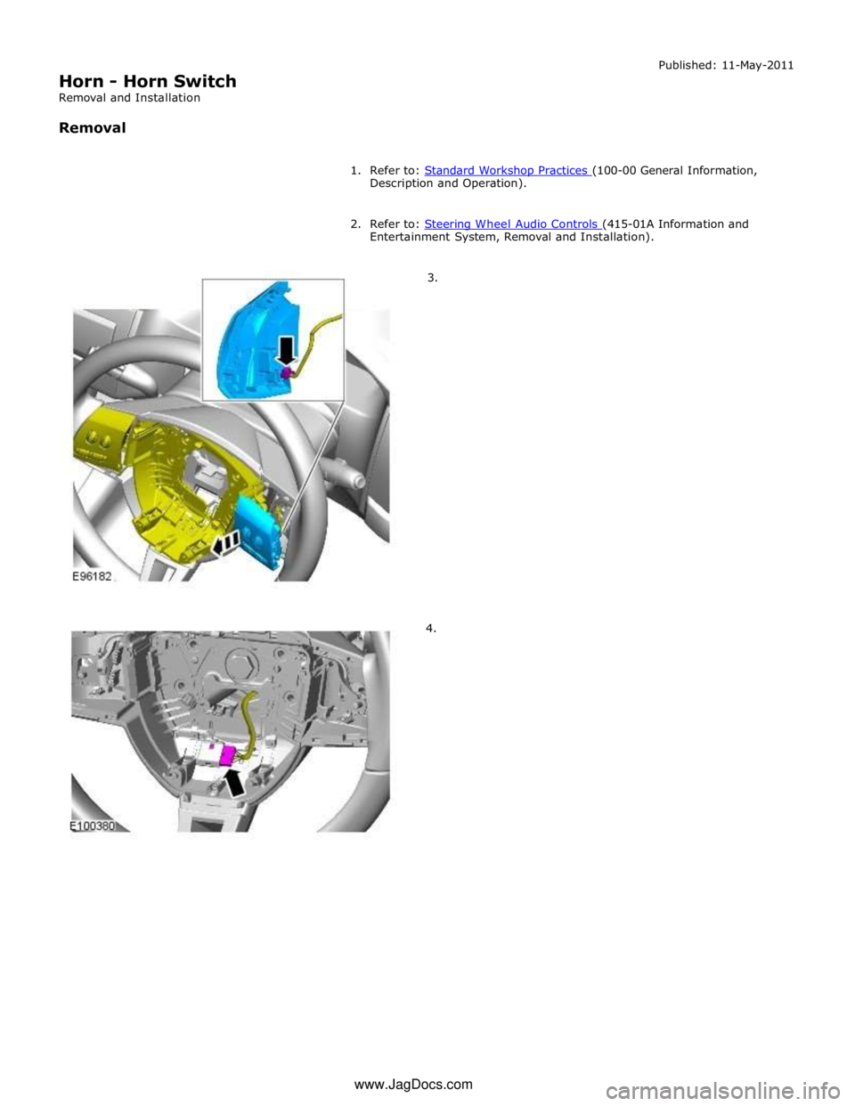
Description and Operation).
2. Refer to: Steering Wheel Audio Controls (415-01A Information and Entertainment System, Removal and Installation).
3.
4. www.JagDocs.com
Page 1822 of 3039
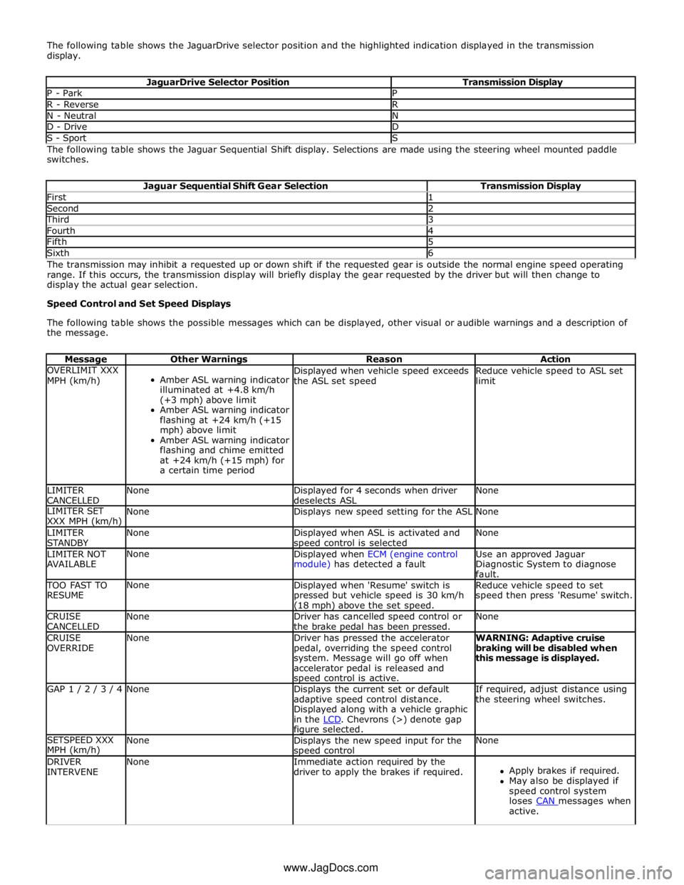
The following table shows the JaguarDrive selector position and the highlighted indication displayed in the transmission
display.
JaguarDrive Selector Position Transmission Display P - Park P R - Reverse R N - Neutral N D - Drive D S - Sport S The following table shows the Jaguar Sequential Shift display. Selections are made using the steering wheel mounted paddle
switches.
Jaguar Sequential Shift Gear Selection Transmission Display First 1 Second 2 Third 3 Fourth 4 Fifth 5 Sixth 6 The transmission may inhibit a requested up or down shift if the requested gear is outside the normal engine speed operating
range. If this occurs, the transmission display will briefly display the gear requested by the driver but will then change to
display the actual gear selection.
Speed Control and Set Speed Displays
The following table shows the possible messages which can be displayed, other visual or audible warnings and a description of
the message.
Message Other Warnings Reason Action OVERLIMIT XXX
MPH (km/h)
Amber ASL warning indicator
illuminated at +4.8 km/h
(+3 mph) above limit
Amber ASL warning indicator
flashing at +24 km/h (+15
mph) above limit
Amber ASL warning indicator
flashing and chime emitted
at +24 km/h (+15 mph) for
a certain time period Displayed when vehicle speed exceeds
the ASL set speed Reduce vehicle speed to ASL set
limit LIMITER
CANCELLED None
Displayed for 4 seconds when driver
deselects ASL None LIMITER SET
XXX MPH (km/h) None Displays new speed setting for the ASL None LIMITER
STANDBY None
Displayed when ASL is activated and speed control is selected None LIMITER NOT
AVAILABLE None
Displayed when ECM (engine control
module) has detected a fault Use an approved Jaguar
Diagnostic System to diagnose
fault. TOO FAST TO
RESUME None
Displayed when 'Resume' switch is
pressed but vehicle speed is 30 km/h (18 mph) above the set speed. Reduce vehicle speed to set
speed then press 'Resume' switch. CRUISE
CANCELLED None
Driver has cancelled speed control or
the brake pedal has been pressed. None CRUISE
OVERRIDE None
Driver has pressed the accelerator
pedal, overriding the speed control
system. Message will go off when
accelerator pedal is released and speed control is active. WARNING: Adaptive cruise
braking will be disabled when
this message is displayed. GAP 1 / 2 / 3 / 4 None
Displays the current set or default
adaptive speed control distance.
Displayed along with a vehicle graphic
in the LCD. Chevrons (>) denote gap figure selected. If required, adjust distance using
the steering wheel switches. SETSPEED XXX
MPH (km/h) None
Displays the new speed input for the speed control None DRIVER
INTERVENE None
Immediate action required by the
driver to apply the brakes if required.
Apply brakes if required.
May also be displayed if
speed control system
loses CAN messages when active. www.JagDocs.com
Page 1824 of 3039
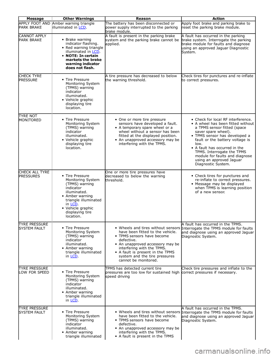
Message Other Warnings Reason Action APPLY FOOT AND
PARK BRAKE Amber warning triangle
illuminated in LCD. The battery has been disconnected or
power supply interrupted to the parking
brake module. Apply foot brake and parking brake to
reset the parking brake module. CANNOT APPLY
PARK BRAKE
Brake warning
indicator flashing.
Red warning triangle
illuminated in LCD. NOTE: In certain
markets the brake
warning indicator
does not flash. A fault is present in the parking brake
system and the parking brake cannot be
applied. A fault has occurred in the parking
brake system. Interrogate the parking
brake module for faults and diagnose
using an approved Jaguar Diagnostic
System. CHECK TYRE
PRESSURE
Tire Pressure
Monitoring System
(TPMS) warning
indicator
illuminated.
Vehicle graphic
displaying tire
location. A tire pressure has decreased to below
the warning threshold. Check tires for punctures and re-inflate
to correct pressures. TYRE NOT
MONITORED
Tire Pressure
Monitoring System
(TPMS) warning
indicator
illuminated.
Vehicle graphic
displaying tire
location.
One or more tire pressure
sensors have developed a fault.
A temporary spare wheel or a
wheel without a sensor has been
fitted at the displayed position.
An unapproved accessory may be
interfering with the TPMS.
Check for local RF interference.
A wheel has been fitted without
a TPMS sensor fitted (space
saver spare wheel).
TPMS sensor has developed a
fault or the battery voltage is
low.
A fault has occurred in the
TPMS. Interrogate the TPMS
module for faults and diagnose
using an approved Jaguar
Diagnostic System. CHECK ALL TYRE
PRESSURES
Tire Pressure
Monitoring System
(TPMS) warning
indicator
illuminated.
Amber warning
triangle illuminated
in LCD. Vehicle graphic
displaying tire
location. One or more tire pressures have
decreased to below the warning
threshold.
Check tires for punctures and
re-inflate to correct pressures.
Message may be displayed
when TPMS is learning position
of a new sensor. TYRE PRESSURE
SYSTEM FAULT
Tire Pressure
Monitoring System
(TPMS) warning
indicator
illuminated.
Amber warning
triangle illuminated
in LCD.
Wheels and tires without sensors
have been fitted to the vehicle.
TPMS sensors have become
defective.
An unapproved accessory may be
interfering with the TPMS.
A fault is present in the TPMS
system and the tire pressures
cannot be monitored. A fault has occurred in the TPMS.
Interrogate the TPMS module for faults
and diagnose using an approved Jaguar
Diagnostic System. TYRE PRESSURE
LOW FOR SPEED
Tire Pressure
Monitoring System
(TPMS) warning
indicator
illuminated.
Amber warning
triangle illuminated
in LCD. TPMS has detected current tire
pressures are too low for sustained high
speed driving Check tire pressures and inflate to the
correct pressures if necessary. TYRE PRESSURE
SYSTEM FAULT
Tire Pressure
Monitoring System
(TPMS) warning
indicator
illuminated.
Amber warning
triangle illuminated
Wheels and tires without sensors
have been fitted to the vehicle.
TPMS sensors have become
defective.
An unapproved accessory may be
interfering with the TPMS.
A fault is present in the TPMS A fault has occurred in the TPMS.
Interrogate the TPMS module for faults
and diagnose using an approved Jaguar
Diagnostic System.
Page 1826 of 3039
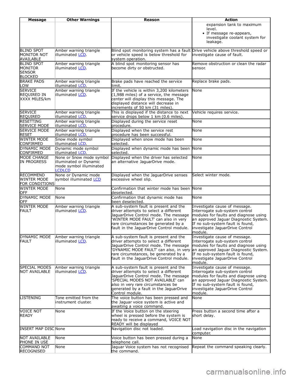
Message Other Warnings Reason Action expansion tank to maximum
level.
If message re-appears,
investigate coolant system for
leakage. BLIND SPOT
MONITOR NOT
AVAILABLE Amber warning triangle
illuminated LCD. Blind spot monitoring system has a fault
or vehicle speed is below threshold for system operation. Drive vehicle above threshold speed or
investigate cause of fault. BLIND SPOT
MONITOR
SENSOR
BLOCKED Amber warning triangle
illuminated LCD. A blind spot monitoring sensor has
become dirty or obstructed. Remove obstruction or clean the radar
sensor. BRAKE PADS
LOW Amber warning triangle
illuminated LCD. Brake pads have reached the service
limit. Replace brake pads. SERVICE
REQUIRED IN
XXXX MILES/km Amber warning triangle
illuminated LCD. If the vehicle is within 3,200 kilometers
(1,988 miles) of a service, the message
center will display this message. The
displayed distance will decrease in
increments of 50 km (31 miles). None SERVICE
REQUIRED Amber warning triangle
illuminated LCD. This is displayed if the distance to next
service drops below 1 km (0.6 miles). Vehicle requires service. RESETTING
SERVICE MODE Amber warning triangle
illuminated LCD. Displayed during the service reset procedure. None SERVICE MODE
RESET Amber warning triangle
illuminated LCD. Displayed when the service rest procedure has been successful. None WINTER MODE
CONFIRMED Snow mode symbol
illuminated LCD. Displayed when snow mode has been
selected. None DYNAMIC MODE
CONFIRMED Dynamic mode symbol
illuminated LCD. Displayed when dynamic mode has been
selected. None MODE CHANGE
IN PROGRESS None or Snow mode symbol
illuminated or Dynamic
mode symbol illuminated
LCDLCD Displayed when the driver has selected
an alternative JaguarDrive mode. None RECOMMEND
WINTER MODE
FOR CONDITIONS None or Dynamic mode
symbol illuminated LCD Displayed when the JaguarDrive senses
excessive wheel slip. Select winter mode. WINTER MODE
OFF None
Confirmation that winter mode has been
deselected. None DYNAMIC MODE
OFF None
Confirmation that dynamic mode has
been deselected. None WINTER MODE
FAULT Amber warning triangle
illuminated LCD. A sub-system fault is present and the
driver attempts to select a different
JaguarDrive Control mode. The message
'WINTER MODE FAULT' can also in very
rare circumstances be generated by a
fault in the JaguarDrive Control module. Investigate cause of message.
Interrogate sub-system control
modules for faults and diagnose using
an approved Jaguar Diagnostic System.
If no sub-system fault is found,
investigate JaguarDrive Control
module. DYNAMIC MODE
FAULT Amber warning triangle
illuminated LCD. A sub-system fault is present and the
driver attempts to select a different
JaguarDrive Control mode. The message
'DYNAMIC MODE FAULT' can also, in very
rare circumstances, be generated by a
fault in the JaguarDrive Control module. Investigate cause of message.
Interrogate sub-system control
modules for faults and diagnose using
an approved Jaguar Diagnostic System.
If no sub-system fault is found,
investigate JaguarDrive Control
module. SPECIAL MODES
NOT AVAILABLE Amber warning triangle
illuminated LCD. A sub-system fault is present and the
driver attempts to select a different
JaguarDrive Control mode. The message
'SPECIAL MODES NOT AVAILABLE' can
also in very rare circumstances be
generated by a fault in the JaguarDrive
Control module. Investigate cause of message.
Interrogate sub-system control
modules for faults and diagnose using
an approved Jaguar Diagnostic System.
If no sub-system fault is found,
investigate JaguarDrive Control
module. LISTENING Tone emitted from the
instrument cluster. The voice button has been pressed and
the Jaguar voice system is active and awaiting a voice command. None VOICE NOT
READY None
If the Voice button on the steering
wheel is pressed before the system is
ready to receive a command, VOICE NOT
READY will be displayed Press button a second time after a
short delay. INSERT MAP DISC None Navigation disc not loaded.
Load navigation disc in the navigation
computer. NOT AVAILABLE
PHONE IN USE None
Voice button has been pressed during a telephone call. None COMMAND NOT
RECOGNISED None
Jaguar Voice system has not recognised
the command. Repeat the command speaking clearly.
Page 1828 of 3039
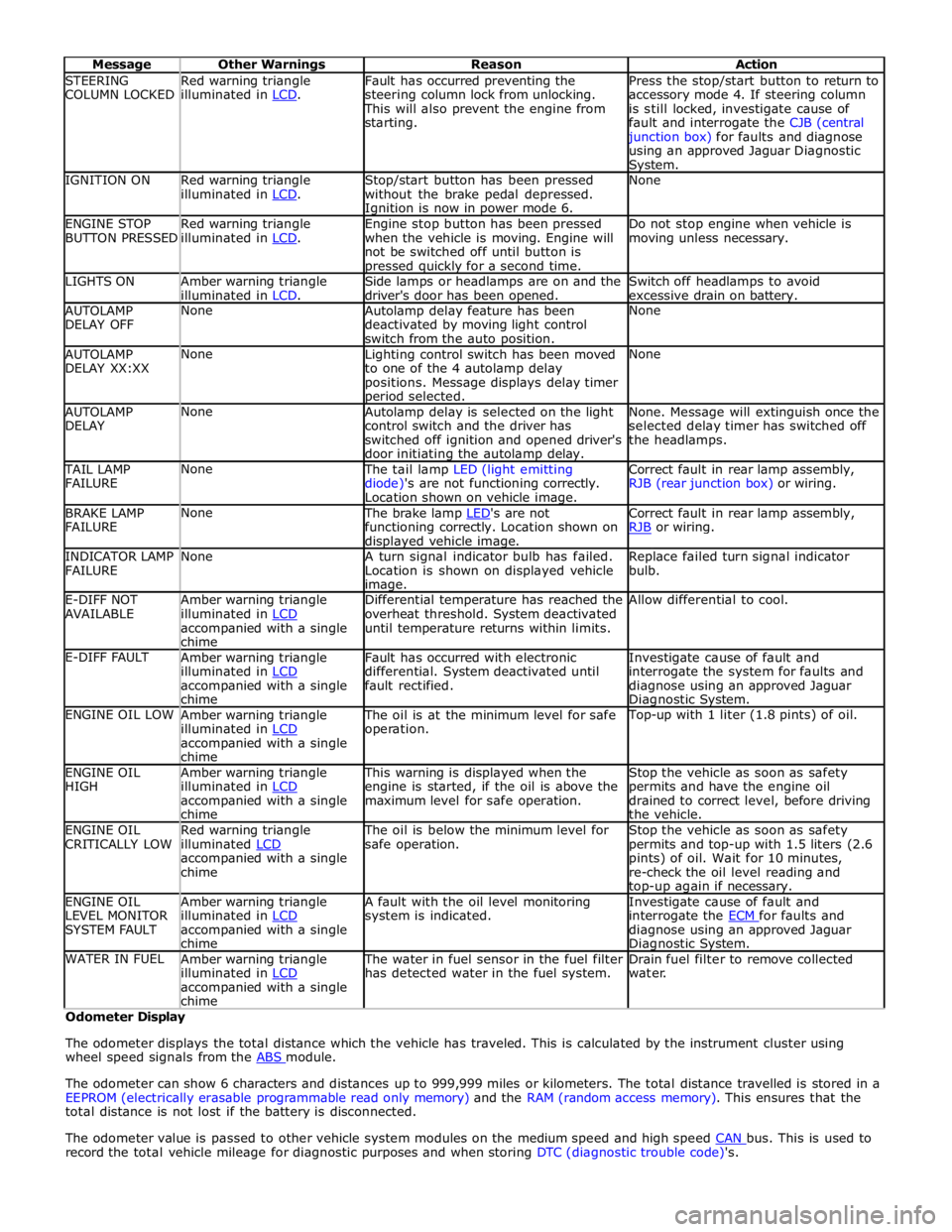
STEERING
COLUMN LOCKED Red warning triangle
illuminated in LCD. Fault has occurred preventing the
steering column lock from unlocking. This will also prevent the engine from
starting. Press the stop/start button to return to
accessory mode 4. If steering column
is still locked, investigate cause of
fault and interrogate the CJB (central junction box) for faults and diagnose
using an approved Jaguar Diagnostic System. IGNITION ON
Red warning triangle
illuminated in LCD. Stop/start button has been pressed
without the brake pedal depressed. Ignition is now in power mode 6. None ENGINE STOP
BUTTON PRESSED Red warning triangle
illuminated in LCD. Engine stop button has been pressed
when the vehicle is moving. Engine will
not be switched off until button is pressed quickly for a second time. Do not stop engine when vehicle is
moving unless necessary. LIGHTS ON
Amber warning triangle
illuminated in LCD. Side lamps or headlamps are on and the
driver's door has been opened. Switch off headlamps to avoid
excessive drain on battery. AUTOLAMP
DELAY OFF None
Autolamp delay feature has been
deactivated by moving light control
switch from the auto position. None AUTOLAMP
DELAY XX:XX None
Lighting control switch has been moved
to one of the 4 autolamp delay
positions. Message displays delay timer period selected. None AUTOLAMP
DELAY None
Autolamp delay is selected on the light
control switch and the driver has
switched off ignition and opened driver's
door initiating the autolamp delay. None. Message will extinguish once the
selected delay timer has switched off
the headlamps. TAIL LAMP
FAILURE None The tail lamp LED (light emitting
diode)'s are not functioning correctly.
Location shown on vehicle image. Correct fault in rear lamp assembly,
RJB (rear junction box) or wiring. BRAKE LAMP
FAILURE None The brake lamp LED's are not functioning correctly. Location shown on displayed vehicle image. Correct fault in rear lamp assembly,
RJB or wiring. INDICATOR LAMP
FAILURE None
A turn signal indicator bulb has failed.
Location is shown on displayed vehicle image. Replace failed turn signal indicator
bulb. E-DIFF NOT
AVAILABLE Amber warning triangle
illuminated in LCD accompanied with a single
chime Differential temperature has reached the
overheat threshold. System deactivated
until temperature returns within limits. Allow differential to cool. E-DIFF FAULT
Amber warning triangle
illuminated in LCD accompanied with a single
chime Fault has occurred with electronic
differential. System deactivated until
fault rectified. Investigate cause of fault and
interrogate the system for faults and
diagnose using an approved Jaguar Diagnostic System. ENGINE OIL LOW
Amber warning triangle
illuminated in LCD accompanied with a single
chime The oil is at the minimum level for safe
operation. Top-up with 1 liter (1.8 pints) of oil. ENGINE OIL
HIGH Amber warning triangle
illuminated in LCD accompanied with a single
chime This warning is displayed when the
engine is started, if the oil is above the
maximum level for safe operation. Stop the vehicle as soon as safety
permits and have the engine oil
drained to correct level, before driving
the vehicle. ENGINE OIL
CRITICALLY LOW Red warning triangle
illuminated LCD accompanied with a single
chime The oil is below the minimum level for
safe operation. Stop the vehicle as soon as safety
permits and top-up with 1.5 liters (2.6
pints) of oil. Wait for 10 minutes,
re-check the oil level reading and top-up again if necessary. ENGINE OIL
LEVEL MONITOR
SYSTEM FAULT Amber warning triangle
illuminated in LCD accompanied with a single
chime A fault with the oil level monitoring
system is indicated. Investigate cause of fault and
interrogate the ECM for faults and diagnose using an approved Jaguar Diagnostic System. WATER IN FUEL
Amber warning triangle
illuminated in LCD accompanied with a single
chime The water in fuel sensor in the fuel filter
has detected water in the fuel system. Drain fuel filter to remove collected
water. Odometer Display
The odometer displays the total distance which the vehicle has traveled. This is calculated by the instrument cluster using
wheel speed signals from the ABS module.
The odometer can show 6 characters and distances up to 999,999 miles or kilometers. The total distance travelled is stored in a
EEPROM (electrically erasable programmable read only memory) and the RAM (random access memory). This ensures that the
total distance is not lost if the battery is disconnected.
The odometer value is passed to other vehicle system modules on the medium speed and high speed CAN bus. This is used to record the total vehicle mileage for diagnostic purposes and when storing DTC (diagnostic trouble code)'s.
Page 1832 of 3039
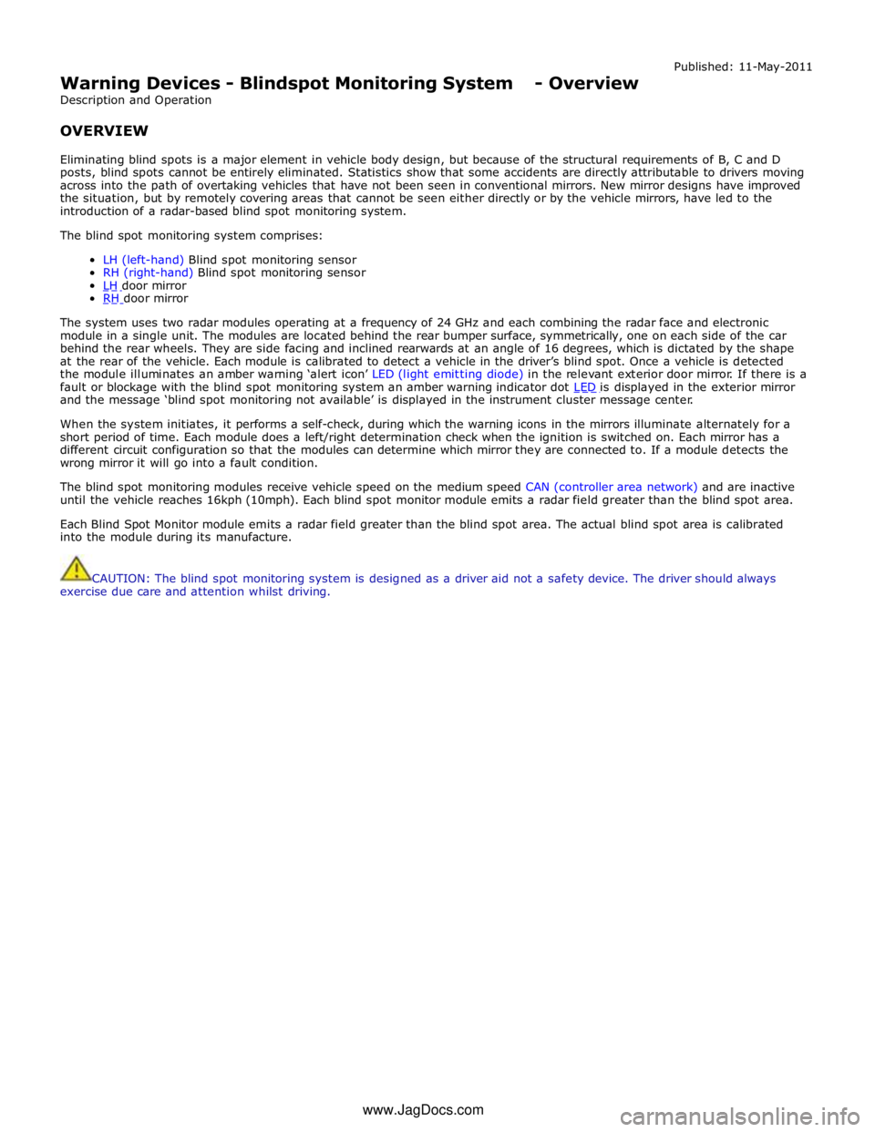
Warning Devices - Blindspot Monitoring System - Overview
Description and Operation
OVERVIEW Published: 11-May-2011
Eliminating blind spots is a major element in vehicle body design, but because of the structural requirements of B, C and D
posts, blind spots cannot be entirely eliminated. Statistics show that some accidents are directly attributable to drivers moving
across into the path of overtaking vehicles that have not been seen in conventional mirrors. New mirror designs have improved
the situation, but by remotely covering areas that cannot be seen either directly or by the vehicle mirrors, have led to the
introduction of a radar-based blind spot monitoring system.
The blind spot monitoring system comprises:
LH (left-hand) Blind spot monitoring sensor
RH (right-hand) Blind spot monitoring sensor
LH door mirror RH door mirror
The system uses two radar modules operating at a frequency of 24 GHz and each combining the radar face and electronic
module in a single unit. The modules are located behind the rear bumper surface, symmetrically, one on each side of the car
behind the rear wheels. They are side facing and inclined rearwards at an angle of 16 degrees, which is dictated by the shape
at the rear of the vehicle. Each module is calibrated to detect a vehicle in the driver’s blind spot. Once a vehicle is detected
the module illuminates an amber warning ‘alert icon’ LED (light emitting diode) in the relevant exterior door mirror. If there is a
fault or blockage with the blind spot monitoring system an amber warning indicator dot LED is displayed in the exterior mirror and the message ‘blind spot monitoring not available’ is displayed in the instrument cluster message center.
When the system initiates, it performs a self-check, during which the warning icons in the mirrors illuminate alternately for a
short period of time. Each module does a left/right determination check when the ignition is switched on. Each mirror has a
different circuit configuration so that the modules can determine which mirror they are connected to. If a module detects the
wrong mirror it will go into a fault condition.
The blind spot monitoring modules receive vehicle speed on the medium speed CAN (controller area network) and are inactive
until the vehicle reaches 16kph (10mph). Each blind spot monitor module emits a radar field greater than the blind spot area.
Each Blind Spot Monitor module emits a radar field greater than the blind spot area. The actual blind spot area is calibrated
into the module during its manufacture.
CAUTION: The blind spot monitoring system is designed as a driver aid not a safety device. The driver should always
exercise due care and attention whilst driving. www.JagDocs.com
Page 1849 of 3039
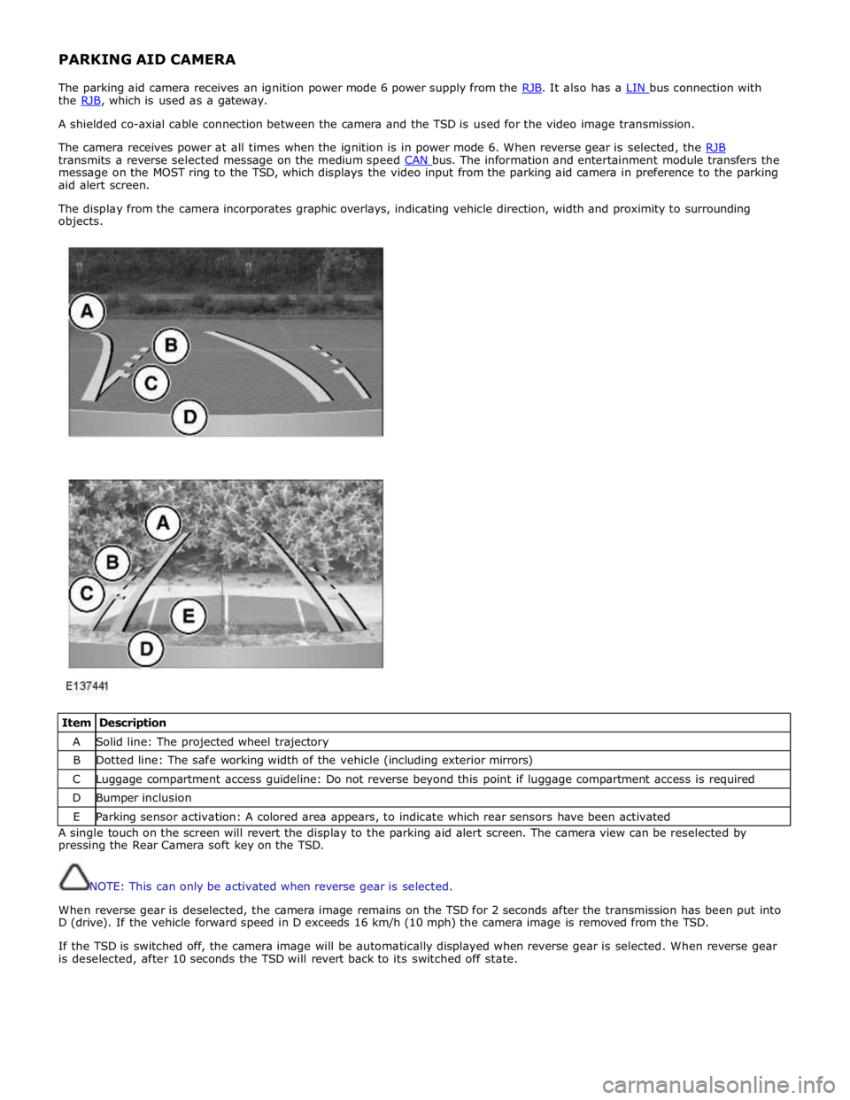
PARKING AID CAMERA
The parking aid camera receives an ignition power mode 6 power supply from the RJB. It also has a LIN bus connection with the RJB, which is used as a gateway. A shielded co-axial cable connection between the camera and the TSD is used for the video image transmission.
The camera receives power at all times when the ignition is in power mode 6. When reverse gear is selected, the RJB transmits a reverse selected message on the medium speed CAN bus. The information and entertainment module transfers the message on the MOST ring to the TSD, which displays the video input from the parking aid camera in preference to the parking
aid alert screen.
The display from the camera incorporates graphic overlays, indicating vehicle direction, width and proximity to surrounding
objects.
Item Description A Solid line: The projected wheel trajectory B Dotted line: The safe working width of the vehicle (including exterior mirrors) C Luggage compartment access guideline: Do not reverse beyond this point if luggage compartment access is required D Bumper inclusion E Parking sensor activation: A colored area appears, to indicate which rear sensors have been activated A single touch on the screen will revert the display to the parking aid alert screen. The camera view can be reselected by
pressing the Rear Camera soft key on the TSD.
NOTE: This can only be activated when reverse gear is selected.
When reverse gear is deselected, the camera image remains on the TSD for 2 seconds after the transmission has been put into
D (drive). If the vehicle forward speed in D exceeds 16 km/h (10 mph) the camera image is removed from the TSD.
If the TSD is switched off, the camera image will be automatically displayed when reverse gear is selected. When reverse gear
is deselected, after 10 seconds the TSD will revert back to its switched off state.