2010 JAGUAR XFR wheel
[x] Cancel search: wheelPage 1851 of 3039

Mechanical Electrical Parking aid control module
Parking aid sounder
Audio system
4. If an obvious cause for an observed or reported concern is found, correct the cause (if possible) before proceeding to
the next step
5. If the cause is not visually evident, check for diagnostic trouble codes (DTCs) and refer to the DTC index
Symptom Chart
CAUTION: Do not apply any grease based products to any parking aid system connector or pins
NOTES:
Please note if this diagnosis is being carried out on a vehicle without a hard wired parking aid speaker, ensure the in car
infotainment system is fully functional and configured correctly
Parking aid sensors that are painted incorrectly and not to the manufacturer standards, will not be considered in any
warranty claim
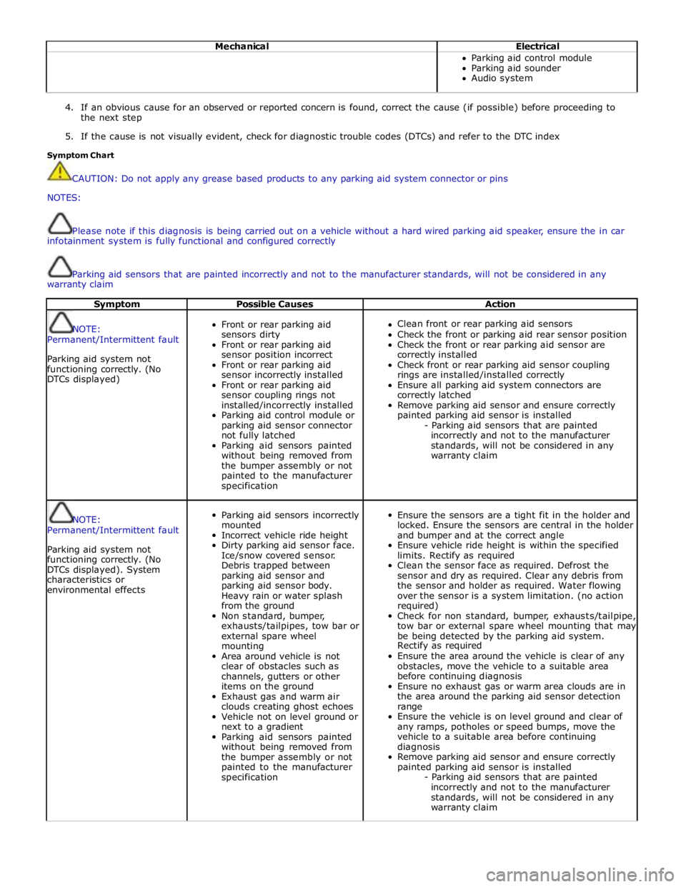
Symptom Possible Causes Action
NOTE:
Permanent/Intermittent fault
Parking aid system not
functioning correctly. (No
DTCs displayed)
Front or rear parking aid
sensors dirty
Front or rear parking aid
sensor position incorrect
Front or rear parking aid
sensor incorrectly installed
Front or rear parking aid
sensor coupling rings not
installed/incorrectly installed
Parking aid control module or
parking aid sensor connector
not fully latched
Parking aid sensors painted
without being removed from
the bumper assembly or not
painted to the manufacturer
specification
Clean front or rear parking aid sensors
Check the front or parking aid rear sensor position
Check the front or rear parking aid sensor are
correctly installed
Check front or rear parking aid sensor coupling
rings are installed/installed correctly
Ensure all parking aid system connectors are
correctly latched
Remove parking aid sensor and ensure correctly
painted parking aid sensor is installed
- Parking aid sensors that are painted
incorrectly and not to the manufacturer
standards, will not be considered in any
warranty claim
NOTE:
Permanent/Intermittent fault
Parking aid system not
functioning correctly. (No
DTCs displayed). System
characteristics or
environmental effects
Parking aid sensors incorrectly
mounted
Incorrect vehicle ride height
Dirty parking aid sensor face.
Ice/snow covered sensor.
Debris trapped between
parking aid sensor and
parking aid sensor body.
Heavy rain or water splash
from the ground
Non standard, bumper,
exhausts/tailpipes, tow bar or
external spare wheel
mounting
Area around vehicle is not
clear of obstacles such as
channels, gutters or other
items on the ground
Exhaust gas and warm air
clouds creating ghost echoes
Vehicle not on level ground or
next to a gradient
Parking aid sensors painted
without being removed from
the bumper assembly or not
painted to the manufacturer
specification
Ensure the sensors are a tight fit in the holder and
locked. Ensure the sensors are central in the holder
and bumper and at the correct angle
Ensure vehicle ride height is within the specified
limits. Rectify as required
Clean the sensor face as required. Defrost the
sensor and dry as required. Clear any debris from
the sensor and holder as required. Water flowing
over the sensor is a system limitation. (no action
required)
Check for non standard, bumper, exhausts/tailpipe,
tow bar or external spare wheel mounting that may
be being detected by the parking aid system.
Rectify as required
Ensure the area around the vehicle is clear of any
obstacles, move the vehicle to a suitable area
before continuing diagnosis
Ensure no exhaust gas or warm area clouds are in
the area around the parking aid sensor detection
range
Ensure the vehicle is on level ground and clear of
any ramps, potholes or speed bumps, move the
vehicle to a suitable area before continuing
diagnosis
Remove parking aid sensor and ensure correctly
painted parking aid sensor is installed
- Parking aid sensors that are painted
incorrectly and not to the manufacturer
standards, will not be considered in any
warranty claim
Page 1858 of 3039

NOTE: The vehicle may take 30 seconds (or 100m) to learn the steering centre position after starting the engine. This is
normal. 1 Start the engine 2 Wait at least 30 seconds 3 Select reverse gear 4 Turn the steering wheel and observe the touch screen Do the tracking lines react to steering input? Yes
No fault present
No
Potential LIN data gateway fault DTC Index
For a list of Diagnostic Trouble Codes (DTCs) that could be logged on this vehicle, please refer to Section 100-00.
Page 1885 of 3039

is operated to crank the engine. The GWM is connected to the ABS (Anti-lock Brake System) control module via the high speed
CAN bus. With the vehicle stationary and the engine off after an ECO engine stop, when the driver releases the brake pedal
the ABS control module senses the reduction in brake pressure. This change of brake pressure state is sent as a high speed
CAN message which is received by the GWM and the ECM. The GWM reacts within 105ms to instruct the DBM via the LIN bus
to operate the two contactors in the DBJB to supply the sensitive loads from the secondary battery and supply the TSS motor
direct from the primary battery.
When the engine is running and the generator is supplying power to the vehicle systems, the GWM again instructs the DBM to
operate the two contactors in the DBJB to supply all vehicle systems from the primary battery and the generator and to isolate
the secondary battery.
Secondary Battery Charging
The DBM also controls the charging of the secondary battery. The GWM contains electrical load management software and
monitors both batteries for their state of charge. The primary battery is monitored by the BMS control module which is
connected to the DBM via the LIN bus. The DBM communicates the primary battery condition to the GWM via a LIN bus
connection. The GWM sends a signal to the DBM via the LIN bus to instruct it to apply charging from the generator to the
secondary battery when required. The contactor 2 is closed by the DBJB to complete the secondary battery circuit, and the
generator output is applied to the secondary battery to charge it.
The generator output is controlled by the GWM which monitors and controls the electrical load management system. The
generator is connected to the GWM by a LIN bus allowing the GWM to control the output of the generator to maintain electrical
system load requirements and battery charging.
Electrical Load Management
The electrical load management is controlled by the GWM and the BMS control module.
The GWM will monitor the vehicle system power loads before and during an ECO engine stop.
Before an ECO engine stop, the GWM will transmit a signal to system control modules on the CAN bus to request a power save
on all electrical loads and set a minimum electrical value override. The GWM monitors the vehicle electrical loads and will
inhibit a ECO engine stop until the load current is at a value low enough to be supported by the secondary battery.
If the electrical loads cannot be reduced sufficiently, the GWM will inhibit the ECO engine stop.
When the engine is stopped after an ECO engine stop, the GWM will continue to monitor the primary battery state of charge.
If the primary or secondary battery voltage falls below 11.0V, a level which will result in degraded starting performance or
possible primary battery damage, the GWM will initiate an engine start.
System Inhibits
The ECO stop/start system is inhibited if the dual battery system is not be capable of preventing electrical loads on the
vehicle being subject to unacceptably low voltage levels during ECO stop/start operations due to a fault.
ECO stop/start inhibit monitoring of the primary battery is performed by the BMS control module. If the primary battery voltage
is too low to support an ECO stop/start, then the BMS control module will send a message to the GWM on the LIN bus to
suspend ECO stop/start.
The GWM monitors the secondary battery and the dual battery system components. Any fault found will cause the GWM to
inhibit ECO stop/start and the GWM will record a DTC (diagnostic trouble code).
Fault Diagnosis
The GWM performs passive and active diagnostics on the dual battery system to determine the status of the system
components.
Passive diagnostics can detect faults in the DBJB and can check for stuck open or closed contactors and failure of DBM
contactor command signals.
Active diagnostics is a routine to test the capability of the contactors to respond to open or close command signals sent from
the GWM to the DBM. This routine also checks the FET's (Field Effect Transistors) activate as required. (Refer to Dual Battery
Junction Box below for description of FET operation)
The GWM will also check the dual battery system components for faults in a controlled environment when the generator is
providing a charging output. This will ensure that the detection of a fault will not result in sensitive electrical loads being
subjected to low voltage which may occur during an ECO stop/start with a fault present.
The GWM will illuminate the charge warning indicator in the instrument cluster if fault is detected in the dual battery system
which will result in a degraded power supply.
If a fault is detected the GWM transmits a CAN message to inhibit ECO stop/start operation. In some cases it will record a
DTC, display a warning message in instrument cluster and also illuminate charge warning indicator.
PRIMARY BATTERY - ALL VEHICLES Component Description
The primary battery is located in a plastic tray under the luggage compartment floor in the right side of the luggage
compartment, adjacent to the spare wheel. The battery is vented via a tube which is connected with a T piece to the vent from
Page 1887 of 3039

DUAL BATTERY MODULE (DBM)
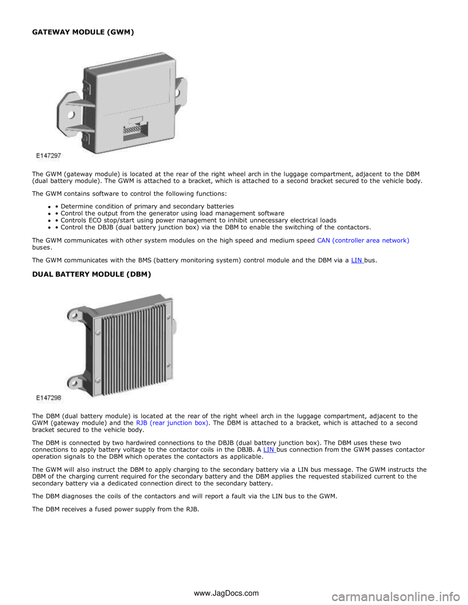
The DBM (dual battery module) is located at the rear of the right wheel arch in the luggage compartment, adjacent to the
GWM (gateway module) and the RJB (rear junction box). The DBM is attached to a bracket, which is attached to a second
bracket secured to the vehicle body.
The DBM is connected by two hardwired connections to the DBJB (dual battery junction box). The DBM uses these two
connections to apply battery voltage to the contactor coils in the DBJB. A LIN bus connection from the GWM passes contactor operation signals to the DBM which operates the contactors as applicable.
The GWM will also instruct the DBM to apply charging to the secondary battery via a LIN bus message. The GWM instructs the
DBM of the charging current required for the secondary battery and the DBM applies the requested stabilized current to the
secondary battery via a dedicated connection direct to the secondary battery.
The DBM diagnoses the coils of the contactors and will report a fault via the LIN bus to the GWM.
The DBM receives a fused power supply from the RJB. www.JagDocs.com
Page 1942 of 3039

lb-ft lb-in Audio antenna unit to "D" pillar retaining bolts 9 - 80 Digital Radio antenna pod retaining nuts 5 - 48 Amplifier retaining nuts 7 - 62 Information and entertainment display retaining bolts 2 - 17 Information and entertainment display mounting bracket to Information and entertainment display retaining bolts 3 - 26 Information and entertainment module retaining bolts 3 - 26 Instrument panel speaker retaining screws 2 - 18 Steering wheel audio control switch retaining screws 3 - 26 Subwoofer amplifier retaining nuts 7 - 62 Subwoofer speaker retaining bolts 6 - 53
Page 1944 of 3039

12 Portable audio interface console (Optional) 13 Portable audio module (Optional) 14 Steering wheel remote audio controls
Page 1947 of 3039

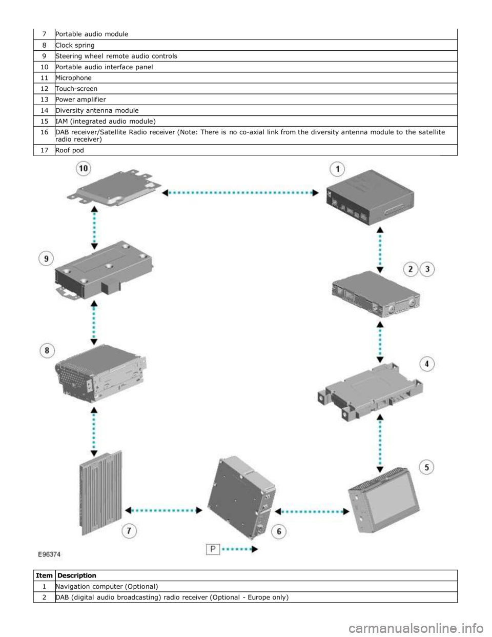
8 Clock spring 9 Steering wheel remote audio controls 10 Portable audio interface panel 11 Microphone 12 Touch-screen 13 Power amplifier 14 Diversity antenna module 15 IAM (integrated audio module) 16 DAB receiver/Satellite Radio receiver (Note: There is no co-axial link from the diversity antenna module to the satellite radio receiver) 17 Roof pod
Item Description 1 Navigation computer (Optional) 2 DAB (digital audio broadcasting) radio receiver (Optional - Europe only)
Page 1949 of 3039

systems.
A typical example of information transfer is vehicle speed information from the ABS (anti-lock brake system) module used to
control the automatic volume control function. The vehicle speed information from the ABS module is sent on the high speed
CAN network and collected by the instrument panel gateway. The signal is passed to the medium speed CAN network and onto the ICM gateway. The ICM calculates the volume adjustment required. The corrected audio volume level signal is sent on the
MOST network to the IAM or Power amplifier (dependant on vehicle equipment level) for output to the speaker system.
AUDIO SYSTEM USER CONTROLS
Touch-Screen
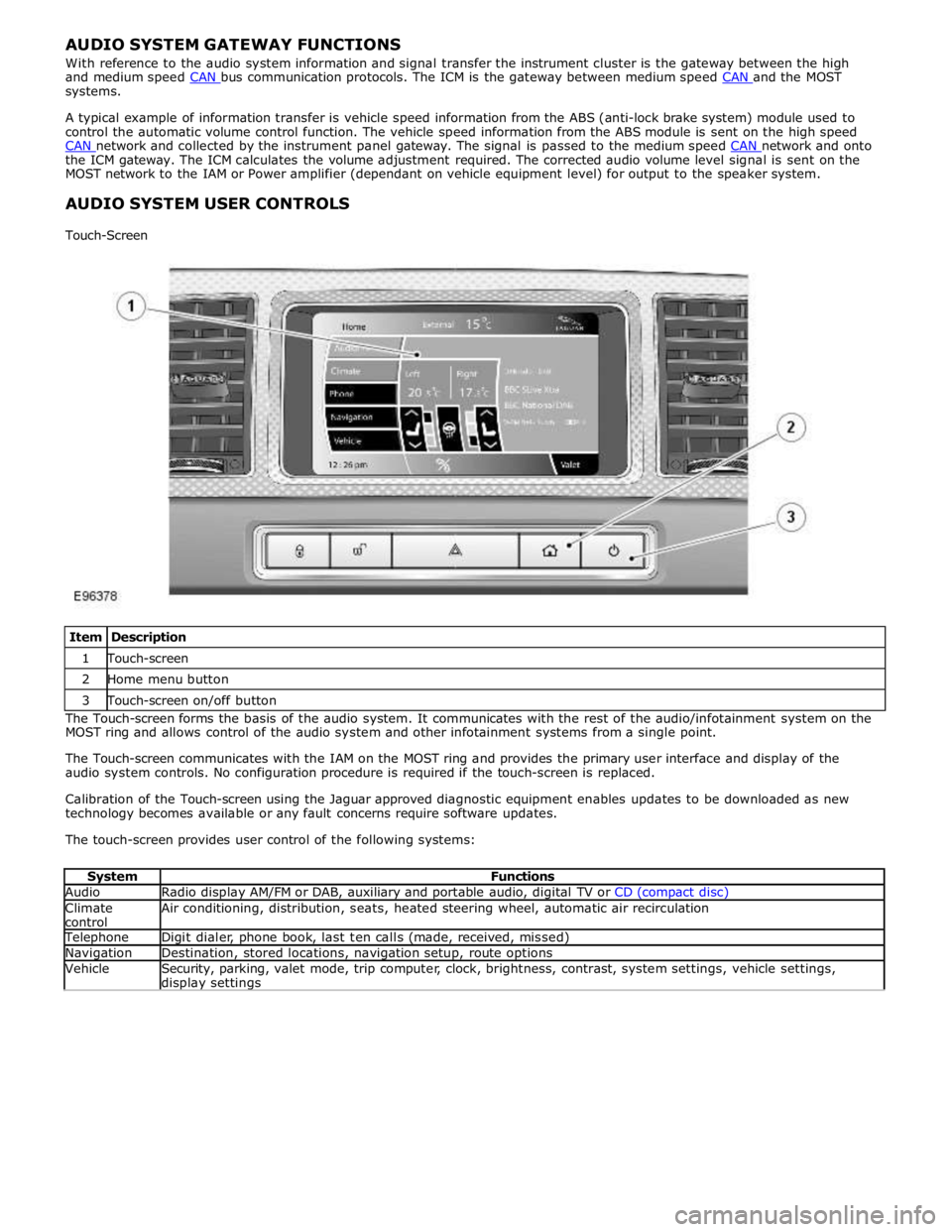
Item Description 1 Touch-screen 2 Home menu button 3 Touch-screen on/off button The Touch-screen forms the basis of the audio system. It communicates with the rest of the audio/infotainment system on the
MOST ring and allows control of the audio system and other infotainment systems from a single point.
The Touch-screen communicates with the IAM on the MOST ring and provides the primary user interface and display of the
audio system controls. No configuration procedure is required if the touch-screen is replaced.
Calibration of the Touch-screen using the Jaguar approved diagnostic equipment enables updates to be downloaded as new
technology becomes available or any fault concerns require software updates.
The touch-screen provides user control of the following systems:
System Functions Audio Radio display AM/FM or DAB, auxiliary and portable audio, digital TV or CD (compact disc) Climate
control Air conditioning, distribution, seats, heated steering wheel, automatic air recirculation Telephone Digit dialer, phone book, last ten calls (made, received, missed) Navigation Destination, stored locations, navigation setup, route options Vehicle
Security, parking, valet mode, trip computer, clock, brightness, contrast, system settings, vehicle settings, display settings