2010 JAGUAR XFR wheel
[x] Cancel search: wheelPage 1362 of 3039
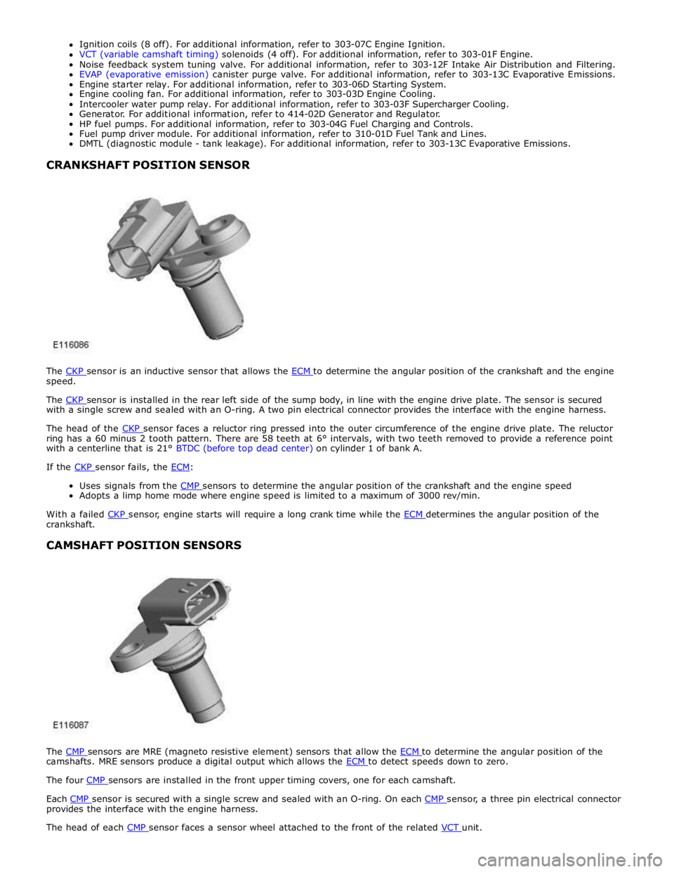
speed.
The CKP sensor is installed in the rear left side of the sump body, in line with the engine drive plate. The sensor is secured with a single screw and sealed with an O-ring. A two pin electrical connector provides the interface with the engine harness.
The head of the CKP sensor faces a reluctor ring pressed into the outer circumference of the engine drive plate. The reluctor ring has a 60 minus 2 tooth pattern. There are 58 teeth at 6° intervals, with two teeth removed to provide a reference point
with a centerline that is 21° BTDC (before top dead center) on cylinder 1 of bank A.
If the CKP sensor fails, the ECM:
Uses signals from the CMP sensors to determine the angular position of the crankshaft and the engine speed Adopts a limp home mode where engine speed is limited to a maximum of 3000 rev/min.
With a failed CKP sensor, engine starts will require a long crank time while the ECM determines the angular position of the crankshaft.
CAMSHAFT POSITION SENSORS
The CMP sensors are MRE (magneto resistive element) sensors that allow the ECM to determine the angular position of the camshafts. MRE sensors produce a digital output which allows the ECM to detect speeds down to zero. The four CMP sensors are installed in the front upper timing covers, one for each camshaft.
Each CMP sensor is secured with a single screw and sealed with an O-ring. On each CMP sensor, a three pin electrical connector provides the interface with the engine harness.
The head of each CMP sensor faces a sensor wheel attached to the front of the related VCT unit.
Page 1373 of 3039

DTC Description Possible Causes Action B10AC-81
Cruise Control Switch -
invalid serial data received
The Engine Control Module
(ECM) has received an invalid
command from the steering
wheel switch pack Clear the DTC and press all the steering wheel
switches, re-check for DTCs. Refer to the
electrical circuit diagrams and check the Cruise
control switch circuit for open circuit, short to
power, short to ground, disconnected. Check
and install a new Steering Wheel Module (SWM) as required. B10AC-82 Cruise Control Switch - alive / sequence counter incorrect / not updated
Cruise Buttons alive counter is
not incrementing. Which
suggests that the LIN bus is
faulty
Steering Wheel Module (SWM) is
not connected
Steering Wheel Module (SWM)
failure Refer to the electrical circuit diagrams and
check the Cruise control switch circuit for open
circuit, short to power, short to ground,
disconnected. Check and install a new Steering
Wheel Module (SWM) as required. B10AC-83
Cruise Control Switch - value
of signal protection
calculation incorrect
Cruise buttons checksum
incorrect, incorrect cruise
switches fitted to vehicle Check and install new cruise switches as
required. B10AC-96
Cruise Control Switch -
component internal failure
Cruise control switch circuit,
open circuit, short to power,
short to ground, disconnected
Cruise Control Switch failure
Steering Wheel Module (SWM)
failure Check for related DTCs in other Central
Junction Box (CJB)s. Refer to the electrical
circuit diagrams and check the Cruise control
switch circuit for open circuit, short to power,
short to ground, disconnected. Check and
install a new cruise control switch as required.
Check and install a new Steering Wheel
Module (SWM) as required. B10FF-68
Ignition Control - Event
information
Spark plug(s) fault
Wiring harness fault
Ignition coil(s) fault Refer to repair manual and check spark plug(s)
for condition and security. Replace any
defective components as required. Refer to
electrical wiring diagrams and check ignition
coil circuit for intermittent open circuit, short
to power, short to ground. Check and install a
new coil(s) as required. B11DB-01
Battery Monitoring Module -
General Electrical Failure
Charging system fault Battery
monitoring signal line
circuit fault
Vehicle battery fault Refer to electrical wiring diagrams and check
charging system for faults. Perform any repairs
required. Refer to the electrical wiring
diagrams and check the Battery Monitoring
System (BMS) module circuit for open circuit,
short to ground, short to power. Refer to the
battery care manual and check and install a
new battery. B11DB-87
Battery Monitoring Module -
missing message
Battery signal line circuit fault Refer to the electrical wiring diagrams and
check the Battery Monitoring System (BMS)
module circuit for open circuit, short to ground,
short to power. B1206-68
Crash Occurred - event
information
Engine control Module (ECM) has
detected the vehicle has crashed
- event information DTC only Refer to the electrical circuit diagrams and
check the Engine Control Module (ECM) to
Restraints Control Module (RCM) circuit for
short to ground, short to power, open circuit.
Repair circuit as required, clear DTC and retest
system to confirm repair. C0031-00
Left Front Wheel Speed
Sensor - No sub type
information
Invalid data received from
Anti-lock Braking System (ABS)
module - left front wheel speed
signal fault Check Anti-lock Braking System (ABS) module
for related DTCs and refer to relevant DTC
Index. C0034-00
Right Front Wheel Speed
Sensor - No sub type
information
Invalid data received from
Anti-lock Braking System (ABS)
module - right front wheel speed
signal fault Check Anti-lock Braking System (ABS) module
for related DTCs and refer to relevant DTC
Index. C0037-00
Left Rear Wheel Speed
Sensor - No sub type
information
Invalid data received from
Anti-lock Braking System (ABS)
module - left rear wheel speed
signal fault Check Anti-lock Braking System (ABS) module
for related DTCs and refer to relevant DTC
Index. C003A-00
Right Rear Wheel Speed
Sensor - No sub type
information
Invalid data received from
Anti-lock Braking System (ABS)
module - right rear wheel speed
signal fault Check Anti-lock Braking System (ABS) module
for related DTCs and refer to relevant DTC
Index.
Page 1410 of 3039
Published: 11-May-2011
Automatic Transmission/Transaxle - TDV6 3.0L Diesel /V8 5.0L Petrol/V8 S/C 5.0L Petrol - Transmission Description - Overview
Description and Operation
OVERVIEW
The ZF 6HP28 transmission is an electronically controlled, hydraulically operated, six speed automatic unit. The hydraulic and
electronic control elements of the transmission, including the TCM (transmission control module), are incorporated in a single
unit located inside the transmission and is known as 'Mechatronic'.
5.1 L SC (supercharger) and 3.0L diesel models use an uprated derivative of the ZF 6HP28 transmission used in the 5.0L
naturally aspirated models.
The ZF 6HP28 transmission has the following features:
Designed to be maintenance free
Transmission fluid is 'fill for life'
The torque converter features a controlled slip feature with electronically regulated control of lock-up, creating a smooth
transition to the fully locked condition
Shift programs controlled by the TCM Electronic park lock, controlled by the TCM, with a mechanical emergency release ASIS (adaptive shift strategy), to provide continuous adaptation of shift changes to suit the driving style of the driver,
which can vary from sporting to economical.
Connected to the ECM (engine control module) via the high speed CAN (controller area network) bus for communications
Default mode if major faults occur
Diagnostics available from the TCM via the high speed CAN bus.
The transmission selections are made using the rotary JaguarDrive selector in the floor console and two paddle switches on the
steering wheel. For additional information, refer to 307-05B Automatic Transmission/Transaxle External Controls - 5.0L/3.0L
Diesel).
Page 1412 of 3039
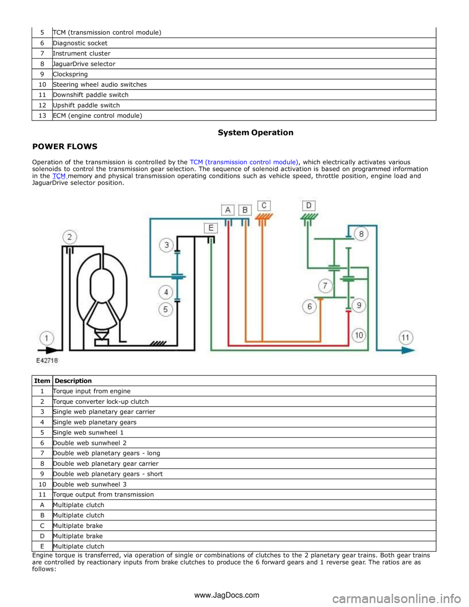
TCM (transmission control module) 6 Diagnostic socket 7 Instrument cluster 8 JaguarDrive selector 9 Clockspring 10 Steering wheel audio switches 11 Downshift paddle switch 12 Upshift paddle switch 13 ECM (engine control module)
POWER FLOWS System Operation
Operation of the transmission is controlled by the TCM (transmission control module), which electrically activates various
solenoids to control the transmission gear selection. The sequence of solenoid activation is based on programmed information
in the TCM memory and physical transmission operating conditions such as vehicle speed, throttle position, engine load and JaguarDrive selector position.
Item Description 1 Torque input from engine 2 Torque converter lock-up clutch 3 Single web planetary gear carrier 4 Single web planetary gears 5 Single web sunwheel 1 6 Double web sunwheel 2 7 Double web planetary gears - long 8 Double web planetary gear carrier 9 Double web planetary gears - short 10 Double web sunwheel 3 11 Torque output from transmission A Multiplate clutch B Multiplate clutch C Multiplate brake D Multiplate brake E Multiplate clutch Engine torque is transferred, via operation of single or combinations of clutches to the 2 planetary gear trains. Both gear trains
are controlled by reactionary inputs from brake clutches to produce the 6 forward gears and 1 reverse gear. The ratios are as
follows: www.JagDocs.com
Page 1413 of 3039
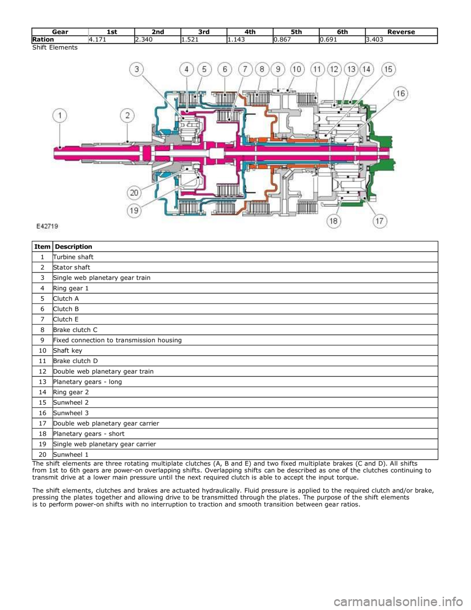
Ration 4.171 2.340 1.521 1.143 0.867 0.691 3.403 Shift Elements
Item Description 1 Turbine shaft 2 Stator shaft 3 Single web planetary gear train 4 Ring gear 1 5 Clutch A 6 Clutch B 7 Clutch E 8 Brake clutch C 9 Fixed connection to transmission housing 10 Shaft key 11 Brake clutch D 12 Double web planetary gear train 13 Planetary gears - long 14 Ring gear 2 15 Sunwheel 2 16 Sunwheel 3 17 Double web planetary gear carrier 18 Planetary gears - short 19 Single web planetary gear carrier 20 Sunwheel 1 The shift elements are three rotating multiplate clutches (A, B and E) and two fixed multiplate brakes (C and D). All shifts
from 1st to 6th gears are power-on overlapping shifts. Overlapping shifts can be described as one of the clutches continuing to
transmit drive at a lower main pressure until the next required clutch is able to accept the input torque.
The shift elements, clutches and brakes are actuated hydraulically. Fluid pressure is applied to the required clutch and/or brake,
pressing the plates together and allowing drive to be transmitted through the plates. The purpose of the shift elements
is to perform power-on shifts with no interruption to traction and smooth transition between gear ratios.
Page 1414 of 3039
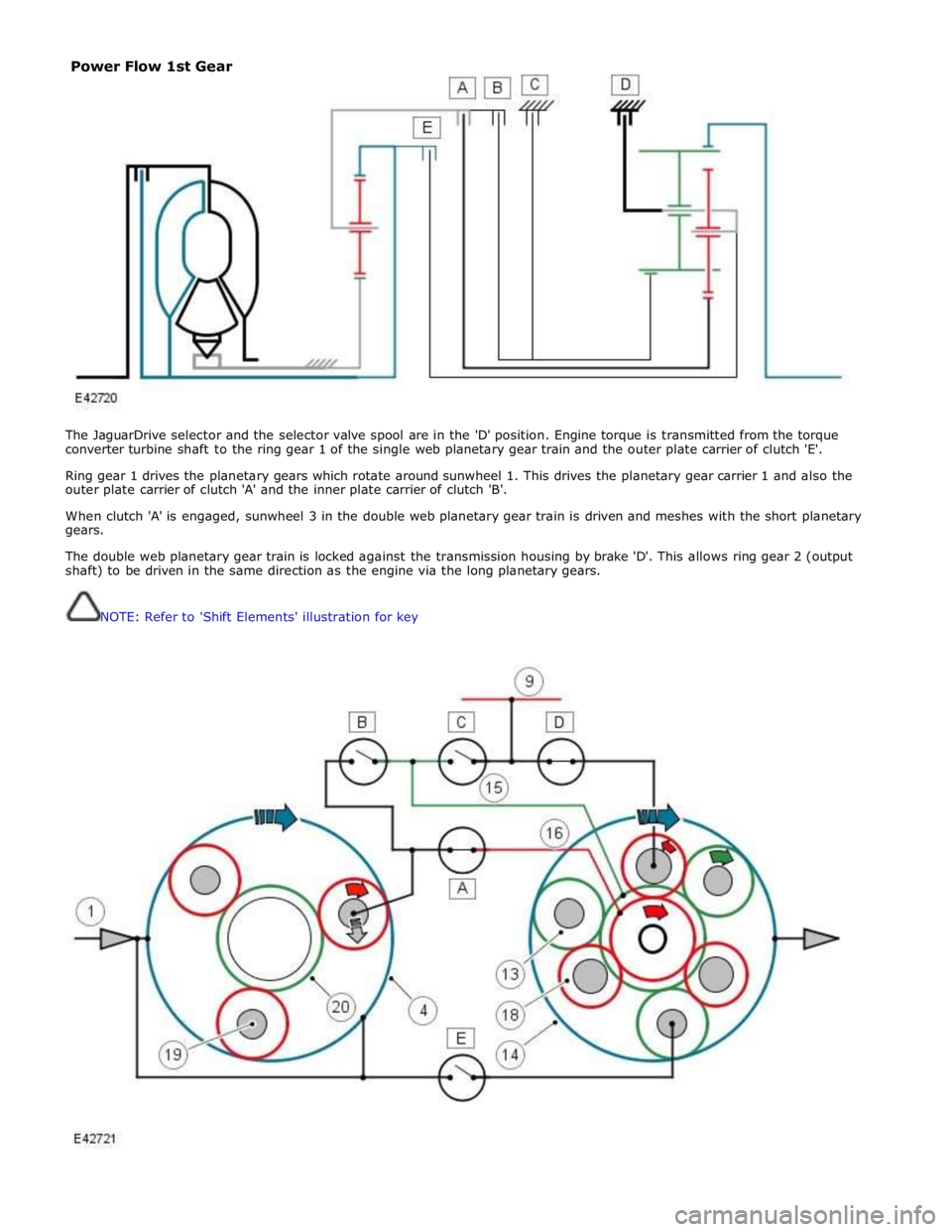
The JaguarDrive selector and the selector valve spool are in the 'D' position. Engine torque is transmitted from the torque
converter turbine shaft to the ring gear 1 of the single web planetary gear train and the outer plate carrier of clutch 'E'.
Ring gear 1 drives the planetary gears which rotate around sunwheel 1. This drives the planetary gear carrier 1 and also the
outer plate carrier of clutch 'A' and the inner plate carrier of clutch 'B'.
When clutch 'A' is engaged, sunwheel 3 in the double web planetary gear train is driven and meshes with the short planetary
gears.
The double web planetary gear train is locked against the transmission housing by brake 'D'. This allows ring gear 2 (output
shaft) to be driven in the same direction as the engine via the long planetary gears.
NOTE: Refer to 'Shift Elements' illustration for key
Power Flow 1st Gear
Page 1415 of 3039
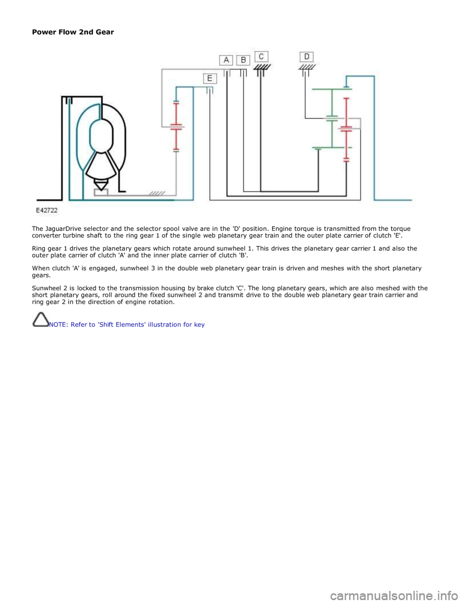
Power Flow 2nd Gear
The JaguarDrive selector and the selector spool valve are in the 'D' position. Engine torque is transmitted from the torque
converter turbine shaft to the ring gear 1 of the single web planetary gear train and the outer plate carrier of clutch 'E'.
Ring gear 1 drives the planetary gears which rotate around sunwheel 1. This drives the planetary gear carrier 1 and also the
outer plate carrier of clutch 'A' and the inner plate carrier of clutch 'B'.
When clutch 'A' is engaged, sunwheel 3 in the double web planetary gear train is driven and meshes with the short planetary
gears.
Sunwheel 2 is locked to the transmission housing by brake clutch 'C'. The long planetary gears, which are also meshed with the
short planetary gears, roll around the fixed sunwheel 2 and transmit drive to the double web planetary gear train carrier and
ring gear 2 in the direction of engine rotation.
NOTE: Refer to 'Shift Elements' illustration for key
Page 1417 of 3039
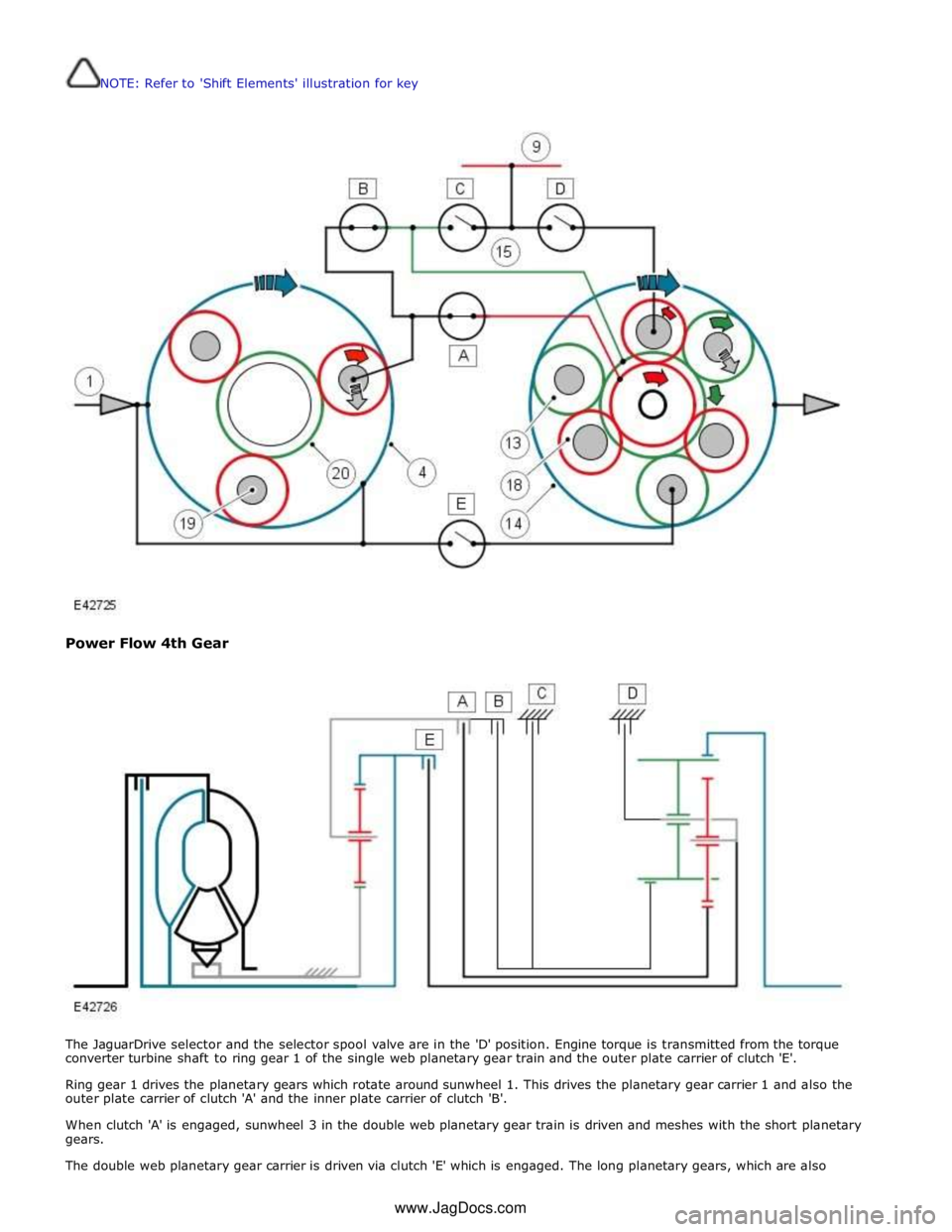
NOTE: Refer to 'Shift Elements' illustration for key
Power Flow 4th Gear
The JaguarDrive selector and the selector spool valve are in the 'D' position. Engine torque is transmitted from the torque
converter turbine shaft to ring gear 1 of the single web planetary gear train and the outer plate carrier of clutch 'E'.
Ring gear 1 drives the planetary gears which rotate around sunwheel 1. This drives the planetary gear carrier 1 and also the
outer plate carrier of clutch 'A' and the inner plate carrier of clutch 'B'.
When clutch 'A' is engaged, sunwheel 3 in the double web planetary gear train is driven and meshes with the short planetary
gears.
The double web planetary gear carrier is driven via clutch 'E' which is engaged. The long planetary gears, which are also www.JagDocs.com