2010 JAGUAR XFR wheel
[x] Cancel search: wheelPage 800 of 3039
path is completed and a signal voltage is returned to the instrument cluster via a resistor. The returned reference voltage is
detected by the instrument cluster and performs the requested trip function.
RIGHT HAND MULTIFUNCTION SWITCH
The instrument cluster outputs 4 separate reference voltages to the following switch functions:
Wash/wipe switch
Intermittent wipe switch
Master wiper switch
Flick wipe switch.
Wash/Wipe Switch
The reference voltage is supplied to one of two resistors connected in parallel. When the switch is not being operated the
current flows through one resistor and the returned signal voltage is monitored by the instrument cluster. When the wash/wipe
switch is operated, a connection is made and the current flows through the second resistor. The change in signal voltage is
detected by the instrument cluster which outputs a message on the medium speed CAN bus to the CJB to activate the wash/wipe function.
Intermittent Delay/Auto Wipe Switch
The reference voltage is supplied to the switch and can pass through up to 7 resistors, connected in series, for intermittent
delay selections and the auto wipe function.
When the rotary switch is in the auto position the reference voltage flows through 1 resistor. The returned signal voltage is
detected by the instrument cluster which determines auto wipe is selected. The instrument cluster outputs a message on the
medium speed CAN bus to the CJB to activate the auto wipe function.
With the rotary switch in one of the intermittent positions, the reference voltage is routed through up to 7 of the resistors
depending on the delay period selected. The returned signal voltage is detected by the instrument cluster which determines
selected delay period. The instrument cluster outputs a message on the medium speed CAN bus to the CJB to activate the selected intermittent wipe function.
NOTE: The delay period for the intermittent selections can vary according to vehicle speed.
Master Wiper Switch
The reference voltage supplied from the instrument cluster to the master wiper switch. The voltage can pass through up to 4
resistors connected in series.
When the switch is in the off position, the reference voltage passes through 4 resistors and the returned voltage is monitored
by the instrument cluster. The instrument cluster outputs a message on the medium speed CAN bus to the CJB that no wiper selections have been requested.
With the switch in the intermittent, slow wipe or fast wipe position, the reference voltage passes through 3, 2 or 1 resistors
respectively. The returned signal voltage is detected by the instrument cluster which determines selected delay period. The
instrument cluster outputs a message on the medium speed CAN bus to the CJB to activate the selected wipe function. Flick Wipe Switch
The reference voltage is supplied to one of two resistors connected in parallel. When the switch is not being operated the
current flows through one resistor and the returned signal voltage is monitored by the instrument cluster. When the flick wipe
switch is operated, a connection is made and the current flows through the second resistor. The change in signal voltage is
detected by the instrument cluster which outputs a message on the medium speed CAN bus to the CJB to activate the flick wipe function.
STEERING COLUMN ADJUSTMENT SWITCH
The instrument cluster supplies 2 reference voltages to the column adjustment switch.
The first reference voltage is supplied to the joystick switch. When the switch is moved to one of its 4 positions, the switch
contact is completed and the reference voltage is passed through one of 4 different resistors with different values. The
returned signal voltage is measured by the instrument cluster which determines the selected column adjust request. The
instrument cluster outputs a supply to the steering column adjustment motor and energizes the applicable clutch solenoid to
move the column to the desired position.
The second reference voltage is supplied to the auto/manual selection of the switch. When the switch is in the auto position,
the reference voltage passes directly through the switch contacts and is measured by the instrument cluster. The instrument
cluster outputs a message on the medium speed CAN bus to the driver seat module which responds with the recorded memory position setting. The instrument cluster then activates the column adjustment motor and clutch solenoids to move the column
to the memorized position. When the switch is in the manual position the reference circuit is broken. The instrument cluster
detects the broken circuit and allows manual operation of the column adjustment switch to move the column.
HEATED STEERING WHEEL
The heated steering wheel receives a battery power supply via the CJB. The heated steering wheel is controlled by the driver using a selection on the TSD. When the driver selects the heated steering wheel to be active, the request is passed from the
TSD on the MOST ring to the information and entertainment module. The information and entertainment module converts the
Page 801 of 3039

battery power supply to be passed via the slip ring assembly in the steering wheel to the heated steering wheel control
module. The steering wheel module supplies power to the steering wheel heater element and also monitors the temperature
via a NTC (negative temperature coefficient) temperature sensor incorporated into the heater element. The control module
varies the power supply to the element to maintain the steering wheel rim at the optimum temperature.
Component Description STEERING COLUMN MULTIFUNCTION SWITCHES
The steering column multifunction switches are situated on the steering column and consists of the wiper switch, the turn
signal indicator/lighting switch and the trip computer switch.
The steering column adjustment switch is located in the steering column lower shroud on the LH side. The switch is a 4 position 'joystick' which controls reach and rake adjustment.
Steering wheel mounted switches on the LH side of the driver's airbag, control the audio and telephone functions. Switches on the RH side of the driver's airbag, control the speed control functions. For additional information, refer to:
Audio System (415-01A Information and Entertainment System, Description and Operation), Speed Control (310-03A, Description and Operation),
Speed Control (310-03B, Description and Operation),
Speed Control (310-03C, Description and Operation).
Two transmission paddle switches are located at the rear of the steering wheel.
Refer to: External Controls (307-05, Description and Operation).
LH Multifunction Switch
Item Description 1 High beam 2 Lighting control rotary switch 3 RH turn signal indicator 4 Headlamp flash 5 LH turn signal indicator 6 Trip computer function button The LH multifunction switch controls the following windshield wiper functions:
Page 803 of 3039

automatically reset once the applicable remote handset has been detected by the vehicle security systems.
STEERING WHEEL HEATER
On certain models the rim of the steering wheel contains a heater element. Operation of the heater is selected using the
Touch Screen Display (TSD).
The heater temperature is controlled by a heated steering wheel control module located within the steering wheel. Power for
the heater element is supplied to the steering wheel via 2 contacts on the clockspring and a slip ring mounted on the steering
wheel.
Page 813 of 3039
Component Tests
Engine Oil Leaks
NOTE: Before installing new gaskets or oil seals, make sure that the fault is clearly established.
If the oil leak cannot be identified clearly by a visual inspection, carry out an Ultraviolet test:
Fluorescent Oil Additive Method
1. Clean the engine with a suitable cleaning fluid (brake cleaner).
2. Drain the engine oil and refill with recommended oil, premixed with Diesel Engine Oil Dye or equivalent. Use a minimum
14.8 ml (0.5 ounce) to a maximum 29.6 ml (1 ounce) of fluorescent additive to all engines. If oil is not premixed,
fluorescent additive must first be added to the crankcase.
3. Run engine for 15 minutes. Stop the engine and inspect all seal and gasket areas for leaks using a 12 Volt Master UV
Diagnostic Inspection Kit or equivalent. A clear bright yellow or orange area will identify leak. For extremely small
leaks, several hours may be required for the leak to appear.
4. As necessary, pressurize the main oil gallery system to locate leaks due to incorrectly sealed, loose or cocked plugs. If
the flywheel bolts leak oil, look for sealer on the threads.
5. Repair all leaks as necessary.
Compression Test General Remarks
NOTES:
Removing fuses and disconnecting electrical components may cause the Engine Control Module (ECM) to log Diagnostic
Trouble Codes (DTCs). After the measurements have been carried out, DTCs should be cleared from memory by connecting to
the Manufacturer Approved Diagnostic System.
Only check the compression pressure with the valves set to the prescribed clearance (if this can be adjusted).
The compression pressure should be checked with the engine at normal operating temperature.
Check the Compression Pressure
WARNING: Move gear selector lever to 'P' position. Failure to follow this instruction may result in personal injury.
1. Remove the fuel pump relay.
2. Start the engine - the engine will start, run for a few seconds then stall.
3. Remove the spark plugs.
4. Install the compression tester.
5. Install an auxiliary starter switch in the starting circuit. With the ignition switch OFF, using the auxiliary starter switch,
crank the engine a minimum of five compression strokes and record the highest reading. Note the approximate number
of compression strokes required to obtain the highest reading.
6. Repeat the test on each cylinder, cranking the engine approximately the same number of compression strokes.
7. Install the removed components in reverse order, observing the specified tightening torques.
8. Clear all DTCs from the ECM.
Interpretation of the Results
NOTE: Due to the possibility of loose carbon that has become trapped between the valve face and seat effecting the
pressure readings, when carrying out a compression test and cylinders are found to have low pressures, install the spark plugs,
road test the vehicle and re-test the suspect cylinders. If the correct pressures are restored, no further action is required.
The indicated compression pressures are considered within specification if the lowest reading cylinder is within 75% of the
highest reading.
If the cylinder pressures are found to be low, carry out a leakdown test to determine the location of the fault (if any leakback
can be heard through the engine breather system suspect the piston rings, if any leakback can be heard through the inlet
system suspect the inlet valve or seat, if any leakback can be heard through the exhaust manifold suspect the exhaust valve
or seat. If the measurements for two cylinders next to each other are both too low then it is very likely that the cylinder head
gasket between them is burnt through. This can also be recognized by traces of engine oil in the coolant and/or coolant in the
Page 1263 of 3039
Published: 11-May-2011
Starting System - V8 5.0L Petrol/V8 S/C 5.0L Petrol - Starting System
Diagnosis and Testing
Principles of Operation
For a detailed description of the starting system and operation, refer to the relevant Description and Operation section of the
workshop manual. REFER to: (303-06C Starting System - V8 5.0L Petrol/V8 S/C 5.0L Petrol)
Starting System (Description and Operation), Starting System (Description and Operation), Starting System (Description and Operation).
Inspection and Verification
CAUTION: Diagnosis by substitution from a donor vehicle is NOT acceptable. Substitution of control modules does not
guarantee confirmation of a fault and may also cause additional faults in the vehicle being checked and/or the donor vehicle.
NOTE: Check and rectify basic faults before beginning diagnostic routines involving pinpoint tests.
1. Verify the customer concern.
2. Visually inspect for obvious signs of mechanical and electrical damage.
Visual Inspection
Mechanical Electrical
Gear selector lever cable adjustment (vehicles with automatic
transmission)
Starter motor
Engine (turns freely)
Battery
Fuses
Starter relay
Wiring harness(es)
Damaged, loose or corroded
connectors
Ignition switch
Generator
Transmission Control Module (TCM)
Engine Control Module (ECM)
3. If an obvious cause for an observed or reported concern is found, correct the cause (if possible) before proceeding to
the next step.
4. If the cause is not visually evident, verify the symptom and refer to the Symptom Chart, alternatively check for
Diagnostic Trouble Codes (DTCs) and refer to the DTC Index.
Symptom Chart
Symptom Possible Causes Action The engine does
not crank (starter
motor does not
turn)
Gear selector not in P or N
position (vehicles with
automatic transmission)
Battery
Starter relay
Invalid key code received by
Central Junction Box (CJB)
Harness/Connectors
Starter motor
Ignition switch
Generator
Transmission Control Module
(TCM)
Engine Control Module (ECM)
Engine seized Make sure the gear selector is in the P or N position and correctly
adjusted. Check the battery condition and state of charge. Check for
DTCs indicating an immobilizer fault. Check the starter motor relay,
ignition switch and generator circuits. Refer to the electrical guides.
Check for TCM and ECM DTCs. Check that the engine turns freely. The engine does
not crank (starter
motor does turn)
Starter motor installation
Starter motor
Flywheel/Drive plate ring
gear Check the starter motor installation (fasteners tight, starter motor
square to engine, etc). Check the flywheel/drive plate ring gear teeth
for damage, foreign objects, etc. www.JagDocs.com
Page 1264 of 3039

Symptom Possible Causes Action Engine cranks too
slowly
Battery
Harness/Connectors
Starter motor
Oil grade Check the battery condition and state of charge. Check the starter
motor circuits. Refer to the electrical guides. Check the engine oil
grade and condition. Engine cranks too
fast
Low engine compression Check the engine compressions. Excessive starter
motor noise
Starter motor
Flywheel/Drive plate ring
gear
Starter motor
installation/casing Check the starter motor installation (fasteners tight, motor square to
engine, etc). Check the starter motor casing condition. Check the
flywheel/drive plate ring gear teeth for damage, foreign objects, etc. DTC Index
For a list of Diagnostic Trouble Codes (DTCs) that could be logged in the Engine Control Module (ECM), please refer to Section
303-14. REFER to:
Electronic Engine Controls (303-14C Electronic Engine Controls - V8 5.0L Petrol, Diagnosis and Testing), Electronic Engine Controls (303-14D Electronic Engine Controls - V8 S/C 5.0L Petrol, Diagnosis and Testing).
Page 1265 of 3039
Starting System - V8 5.0L Petrol/V8 S/C 5.0L Petrol - Starting
System Vehicles With: Smart Key
Diagnosis and Testing
Principles of Operation Published: 06-Apr-2013
For a detailed description of the starting system, refer to the relevant Description and Operation section in the workshop
manual.
Inspection and Verification
1. Verify the customer concern.
2. Visually inspect for obvious signs of mechanical or electrical damage.
Visual Inspection
Mechanical Electrical
Steering column
Brake pedal
Smart key
Steering Wheel
Fuses
Harnesses and connectors
Warning lamp operation
Smart key operation
Engine start operation
3. If an obvious cause for an observed or reported concern is found, correct the cause (if possible) before proceeding to
the next step.
4. If the cause is not visually evident, check for Diagnostic Trouble Codes (DTC's) and refer to the DTC Index.
5. Check DDW for open campaigns. Refer to the corresponding bulletins and SSM's which may be valid for the specific
customer complaint and carry out the recommendations as needed.
CAUTIONS:
Diagnosis by substitution from a donor vehicle is NOT acceptable. Substitution of control modules does not guarantee
confirmation of a fault, and may also cause additional faults in the vehicle being tested and/or the donor vehicle
When probing connectors to take measurements in the course of the pinpoint tests, use the adaptor kit, part number
3548-1358-00
NOTES:
If the control module or a component is suspect and the vehicle remains under manufacturer warranty, refer to the
warranty policy and procedures manual (section B1.2), or determine if any prior approval programme is in operation, prior to
the installation of a new module/component.
Generic scan tools may not read the codes listed, or may read only 5-digit codes. Match the 5 digits from the scan tool to
the first 5 digits of the 7-digit code listed to identify the fault (the last 2 digits give extra information read by the
manufacturer-approved diagnostic system)
When performing voltage or resistance tests, always use a digital multimeter accurate to three decimal places and with a
current calibration certificate. When testing resistance, always take the resistance of the digital multimeter leads into account
Check and rectify basic faults before beginning diagnostic routines involving pinpoint tests
Inspect connectors for signs of water ingress, and pins for damage and/or corrosion
If diagnostic trouble codes are recorded and, after performing the pinpoint tests, a fault is not present, an intermittent
concern may be the cause. Always check for loose connections and corroded terminals
Symptom Chart
Symptom - Message Displayed Symptom - Possible Cause Action Smart key not found - Refer to handbook Ignition mode fails to switch on GO to Pinpoint Test A.
Page 1267 of 3039
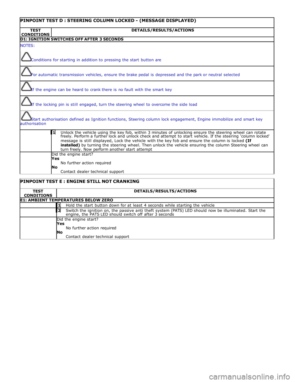
PINPOINT TEST D : STEERING COLUMN LOCKED - (MESSAGE DISPLAYED) TEST
CONDITIONS DETAILS/RESULTS/ACTIONS D1: IGNITION SWITCHES OFF AFTER 3 SECONDS NOTES:
Conditions for starting in addition to pressing the start button are
For automatic transmission vehicles, ensure the brake pedal is depressed and the park or neutral selected
If the engine can be heard to crank there is no fault with the smart key
If the locking pin is still engaged, turn the steering wheel to overcome the side load
Start authorisation defined as Ignition functions, Steering column lock engagement, Engine immobilize and smart key
authorisation 1 Unlock the vehicle using the key fob, within 3 minutes of unlocking ensure the steering wheel can rotate freely. Perform a further lock and unlock check and attempt to start vehicle. If the steering 'column locked'
message is still displayed, Lock the vehicle with the key fob and ensure the column is locked (If
installed) by turning the steering wheel. Then unlock the vehicle ensuring the column Steering wheel can
turn freely. Now perform another start attempt Did the engine start?
Yes
No further action required
No
Contact dealer technical support
PINPOINT TEST E : ENGINE STILL NOT CRANKING TEST
CONDITIONS DETAILS/RESULTS/ACTIONS E1: AMBIENT TEMPERATURES BELOW ZERO 1 Hold the start button down for at least 4 seconds while starting the vehicle 2 Switch the ignition on, the passive anti theft system (PATS) LED should now be illuminated. Start the engine, the PATS LED should switch off after 3 seconds Did the engine start? Yes
No further action required
No
Contact dealer technical support